locked motor labview
Hello world
I've got this VI and it takes data series of a touch screen and it goes through a regulator PID to some engines using the myRIO. The VI on startup, engine will assume their original position and then LabVIEW will break. I really need this help to solve this problem and get the VI to run smoothly.
Thank you very much
James
Tags: NI Software
Similar Questions
-
question on locking of LabVIEW amplifier design
Hi all
I use myDAQ with the NI DAQPad-6259 pinout for the input signal measurement. and I want to build an amplifier to lock by labview to measure the input signal. Does anyone have this kind of tutorials or vedios that enjoy helping me build this? I didn't use the Toolbox, but trying to figure out how to build and why it should be.
Thank you.
Look here:
http://www.NI.com/white-paper/5613/en/
http://forums.NI.com/T5/dynamic-signal-acquisition/lock-in-amplifier/TD-p/1057126
http://forums.NI.com/T5/LabVIEW/lock-in-amplifier-using-NI-USB-6251/TD-p/1550972
http://forums.NI.com/T5/dynamic-signal-acquisition/lock-in-amplifier-and-DAQmx/TD-p/282419
-
Hi all
I need to drive a lock when the button signal operated with a Boolean value. How can I do?
PS I don't have the button in the front panel... but I need to change a Boolean value into a momentum.
Thank you
I solved with a feedback node.
Thank you
-
Laser digital lock with Labview FPGA?
Hello
Sorry to bother if you are not interested in this issue of digital signal processing. We are looking for a possible digital solutions to our problem locked frequency cavity closed-loop laser (see attached PDF file for more details). The goal is to flatten the PZTs transfer function (cancel the resonances and anti-resonances and their phase shift matching) in the frequency domain, in addition to the normal PID control. Input/output necessary voltage signals are small (we have our own amplifiers high power for the PZTs), and their bandwidth must be at least of 50 kHz (100 kHz would be optimal).
Among various OR hardware/software (DSP, FPGA, cRIO etc.), would anyone recommend a cost-effective solution for rapid prototyping?
Thank you!
I would like to look at the FPGA PXI cards nor 7854r. I rate of 750 kHz, 1 MHz AO. According to the involved treatment, you might expect between 200 and 750 kHz closed control loop. If the treatment is very intense, it's probably something less than 200 kHz.
That said, the key to these performance levels is not trivial and great care and attention to detail must be used in the coding of the FPGA.
Good luck
-
locking using NI USB-6251 amplifier
Hi all:
I'm in the very initial stages of development of spectroscopy (FMS) frequency modulation experience on my set-up of already existing absorption spectroscopy. I know that I'll need an amplifier to lock to select the signal at a specific frequency. I already have an acquisition card of NI USB-6251 data which works very well and I've used for my experiments of absorption spectroscopy. I was wondering if there is a way to create an amplifier to locking vi which uses the NI USB 6251 casing and would do what I need for my FMS experience. I try to avoid buying another instrument, if I do not need.
Anyone who is familiar with amplifier locking vi and see if I can put it with my USB NI 6251? Thank you!
Alfredo
Herea link to the use of an amplifier to locking using LabVIEW. However these specific VI were designed to use our acquiring dynamic signals of maps that isn't the 6251. You can try using a simple bandpass filter in the software, but it is certainly not an ideal situation in any stretch of the imagination. But with only the 6251, it is certainly an option.
Kind regards
Brian P
-
Modify Boolean value on time when you press the button. (set lock time?)
Is it possible to set a time to lock in LabVIEW? Rather than change the Boolean value for just a sample, I need the value changed for 0.05 seconds. This problem seems very simple, but my programming skills are faulty.
To simply explain what makes my program, it simulates a sine wave when a button is clicked. I then the amplitude of the sine wave, controlled by another case within the structure structure master case (if I can call it that). Set to false for the structure of business range is 5. When a key is pressed, I need the case structure change true 0.05 seconds, changing the amplitude to 10. The structure of the case must then return false and generate its initial magnitude of 5.
Is it possible to program very simply? If only I could have a latch to set time button.
Yes. When the button is true, store the current time in a shift register (If false, collar shift enter thread through unchanged). Each iteration of the loop, compare the current time to the shift register times. If the values are less than or equal a.05, then run the true case of your case amplitude structure. (In fact, I found myself using Select statements for this example.)

-
With the help of Lego sensors and motors through the LabVIEW and NI PCI card
I want to connect a card PCI NI Lego motors and sensors and drive motors and the data of sense using LabView. What card PCI can I use? Thanks for a great site and fantastic community online.
Hi Tom,
Looks like a great app. NXT with LabVIEW Migration will be a big intermediate step before joining more industrial and better sensors with a PCI, PXI, cDAQ or cRIO. We have a lot of options when it comes to vision and control and acquisition of movement, and we have dedicated forums for all of these products as well.
Machine vision: http://forums.ni.com/t5/Machine-Vision/bd-p/200
Motor control and motor control: http://forums.ni.com/t5/Motion-Control-and-Motor-Drives/bd-p/240
Programming LEGO Mindstorms LabVIEW Guide: http://digital.ni.com/manuals.nsf/websearch/93B7EC451C8DEEC68625762B005380FE
Getting started with LEGO Mindstorms: http://digital.ni.com/manuals.nsf/websearch/80456522F9BE87FB8625746400540977
Good luck
-
SRS problem lock at the labview program amplifier with regard
Madam, Sir, I have a labview program for SRS 830 lock in amplifier and problem is that the output is depends on the sensitivity... as we change sensitivity 500mv to 1v then exit hydro-huileuses changes. automatic gain function does not work. I'm so amazing that, about what the sensitivity, the output is correct. Please, help me to overcome this problem by starting the function of automatic gain. I enclose you than vi. When I run vi to autogain, then it displays an error and stop.
'This error' mean? Time-out error or a parameter? If it is a parameter error, definitely check the manual to see if this is supported.
-
LabView program for lock-in-amp
Hello
I have to read the voltage level of a Lock-In-Amp and on the other to read the magnetic field of a Gaussmeter, simultaneously. After that, I should I establish a curve of respect of tension on the ground. Please give me some tips to write a good program with LabView to the stated purpose.
Records,
The program to read from the hardware depends entirely on the hardware you have. Should what commands you send? In what format the data is returned? (Your next step is to 1) check with the manufacturer to see if the LabVIEW drivers available or 2) to determine how to communicate correctly with the hardware.
After that you are able to read a value from each of the devices, the next step is to place them in a loop and the wire to a chart. (loops are graphics are basic and there are a lot of examples).
Now another question; you said you're tracing the curve tension against the magnetic field, then how we control the field? Do you also need to add the control of the magnetic field?
-
Linear actuator, motor controller and labview. Establishing a connection.
Overview:
I have a 12VDC linear actuator (potentiometer built in) connected to the and 21v3 Jrk USB motor with Feedback Controller (http://www.pololu.com/catalog/product/1392). Feedback from the actuator wires connect to the motor controller motor USB controller connects to the computer via USB.Problem:
Establish the connection between the motor controller and labview.What I've done so far:
I installed the drivers for the motor controller and windows detects it. OR MAX detects my motor controller (photo attached), but for some reason when I try to access it via the daq assistant in labview is not see it. I tried also access it through VISA with no result...
Help will be appreciated.
Thank you
Peter
You have some things you have to look in:
- When you have installed the software, he was installing a USB > dll Com Port virtual as FTDIchip or similar? If so, when connect you your device, it will reveal itself as a normal COM (new) Port in Device Manager. You then try to talk to this COM port.
- If you try to use the USB native on the map (as MAX has detected for you), then you will need to use the code in the .NET framework provided by the manufacturer (probably written in c#) and do your own builders in LabVIEW. If you have never done this before, it's not trivial.
I would call the manufacturer and just tell them what you're trying to do. They have probably treated before LabVIEW and can have an example to help you get started.
Edit: for fun, I followed the link you provided (which doesn't really). I searched "LabVIEW" of their site and indeed has achieved several successes. There is one thing that I downloaded (can't resist looking at code) was a gigantic turd. However, it doesn't use a standard Com port.
-
Maxon motor control with LabView
Hello everyone, I'm new here and I tried to find out how this process of work for some time and I ran out of options. LabView is very difficult to understand.
I'm about to order a controller epos Maxon motor 24/5. I have a vi that does what I do, but I need to find a way to make the process faster. Basically will control a wing that goes forward and backward at very high speeds. I'm not sure what I should do, I would also like to generalize the process by a power enter a function or a wave of the position of my choice. If any of you all can help me it will be greatly appreciated. Thanks in advance.
CarlosUT,
Without the subVIs Epos, it is difficult to say where downturns could be.
Take into account:
1. the mathscript node is probably much slower than native LabVIEW, special code for what looks like a logic very simple. Replace with the range of comparison functions. Also consider the feedback node initialization so that you know where it starts when the VI is called.
2. learn a few basics of data flow. Your delay (ms) and judgment is read only once at the beginning of the VI and these original values are passed to the loop. Any subsequent changes to these values will not see inside the loop. Move the terminals in the loop.
3. double code: you have the same Subvi in each case in the structure of the case. Move the Subvi outside the structure of the case and simply use the box structure to choose which set of values will be used.
4. given that the minimum value of the delay (ms) is 150, the loop cannot run more than about 6 times per second. You don't specify what you mean by high speeds for the control of the wing, but this may be a factor.
Lynn
-
How to control an electric motor using LabVIEW?
Hello
is there a simple way to control the rotation speed of an electric motor (12V) using LabVIEW?
I have an idea how to achieve this using the card OR measurement, its not that cheap. Any ideas?
Maciek.
-
Need help with LabVIEW code for motor control.
Hello
My name is Sasi. I'm a grad student BME working on my thesis topic of assessment for back pain spine implants. To do this, I'm building a test machine that would apply pure moments of a specimen of the spinal column. I use LabVIEW 8.5 to implement the control of a brushless AC servo motor. My requirement is
Step 1: Initialize the engine.
Step 2: Start moving it to a uniform to the right PLAN (this value of RPM too user can enter).
Step 3: while doing step 2; at the same time read the couple cell data (acquisition of data using Asst.). DAQ o/p is 0 v to 10 V; 0 v is 10 Nm n
10 v is + 10 Nm
Step 4: What torque reached + 10 Nm, i.e. 10 V, the engine stops.
Step 5: from the position where the motor stopped (IE not need to return to the initial position) start moving in the opposite direction to the same
Uniform rpm as in step 2 at the reading of data in the cells of the couple.
Step 6: once more what torque reached-10 Nm, i.e. 0 V, the engine should stop.
Step 7: Repeat "Step 2" to the "step 6' 3 times.
Step 8: Reset engine position.So far, I managed to get the engine to move backward @ a desired vel, the accl, deceleration for 3 cycles before n n. I enclose my code. I have a problem inserting the code for reading DAQmx amidst all this. Can someone help me.
Thnks,
Sasi.
Hi Sonia,.
I took a quick glance to your problem and I think I have a solution for you. I certainly agree with the suggestion of the use of parallel loops Lynn. This will allow the portion DAQmx run uninhibited by the part of the motion, and vice versa. In addition, you need only perform an iteration of the loop of the movement whenever the voltage level exceeds a threshold. Thus, by performing an iteration on the code of movement in the same loop are you iterate over DAQmx code, you essentially waste processor.
I created a VI that should do what you are wanting. I tested it on me and it works very well. You have a tweak a few things to apply to your system (such as motion Council DAQmx and physical channel ID, etc.). I used two parallel loops and event programming. Basically, the loop of movement starts the engine turns at the specified speed. Once the engine is running, he expects the DAQmx loop to tell him that the voltage value has crossed the threshold. When the voltage value exceeds the maximum threshold (I put a value slightly less than 10 to jitter and saturation), the DAQmx loop indicates the loop of the motion that it may end its iteration. The motion loop stops the motion, causes a reversal and repeats the motion. Once the movement has begun, he expects the DAQmx loop once again to tell him that a threshold was held, but this time, it's looking for a minimum threshold. I used "Occurrences" to implement the event programming in LabVIEW.
I've commented the code pretty thoroughly, so I hope that comments will answer all remaining questions. The advantage of using programs that focus on the event for this is that you save time processor, and your movement is more closely synchronized with the DAQmx. Instead of one iteration of the loop of movement as fast as you can, updates every hour, you just put in pause and wait for the other loop to tell you when to start up again. Meanwhile, the processor doesn't have to worry about an iteration of this loop over and over again. In addition, when the accident occurs, you catch him immediately, instead of having to wait until the next iteration. Thus, you are more closely synchronized with the DAQmx code portion.
I hope this will help you. Please report if you have any questions about the code or its implementation. Good luck!


-
Impossible to acquire the lock on Fluke 45 COM1 series in LabVIEW
When the ECHO of multimeter Fluke setting is enabled, the following occurs using the Panel to test VISA OR max:
- In the VISA sign, a write command is sent to write * IDN? \r to the multimeter. No error, the DMM accepts the order.
- In the VISA sign, a reading command is sent and the DMM previous writing echoes (* IDN? \r) command to the VISA sign
- In the VISA sign, a reading command is sent, then the DMM shows the output of the command "write" (FLUKE, 45, [redacted] sn, D1.0\r\n 1.7)
- In the Panel VISA, a read command is sent, and then the DMM indicates that the "write" command has been received and executed successfully using default BOM of the DMM (-online \r\n)
Note that this is quite the same when ECHO is turned off, except that step 2 does not occur.
Now, it's quite identical to the output during the next show the * IDN? order Tera Term:
* IDN?
Fluke, 45, [redacted] sn, 1.7 D1.0
=>
(Tera term, does not display the CR (\r) or line feed (\n) as does the VISA Committee).
Thus, it would seem that the VISA panel communicates with the DMM in the same way as terminal, it is simply not actively reading such as Tera term and requires the user to request a read line.
What I don't understand is the difference between the behavior of the DMM when you use the Tera term or the Panel test VISA and when using LabVIEW.
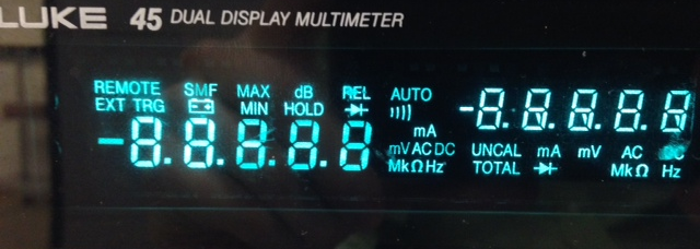
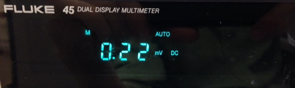
When communicating with the DMM in terms of Tera or the VISA sign, the digital multimeter answers ranging from 1 view state to indicate status 2 (see images below). When you try to use even the simplest example communication series live or the driver plug-and-play Fluke screws, the DMM remains to view state 1. Note that the change of State 1 to State 2 happens only after the launch of a connection in Tera term or the VISA sign; so, I think I'm having a problem where LabVIEW is unable to acquire a lock for communication with the instrument series.
If someone has some, please let me know if you have a way to solve this particular problem.
Display status 1:
Display state 2:
-
AKM21C using LABVIEW servo motor control
Hello
I'm controlling only 3 engine AKM21C using LABVIEW. I want a user to enter a certain length and width to move the motor in x-y-directions, and through the GUI LABVIEW on the façade. Two of the engines must evolve synchronously in the direction, while the third engine moves in. x I have a query UMI-7774 interface connected to the reader of the AKD engines.
Could someone please guide me on how to proceed with this?
Hello
Assuming you are using one of our motion controller cards, follow-up guide will be an excellent aid step by step to get you started: http://www.ni.com/pdf/manuals/375543c.pdf.
Maybe you are looking for
-
Z510 gets dirty fast how to clean screen and keyboard and coverage
I have a z510, always gets dirty fast, on the screen and keyboard and the coverage, how can I clean up the mess without harming the laptop Note of the moderator; subject published
-
HP mini 110 ask current password and do not start computer
Hi I was wondering if you can help with a password. I get the CNU9362H8L error code after three unsuccessful attempts
-
Hey! I wouldn't exactly say this a material issue, but today I experimented a little with my machine. All the equipment had been disconnected and reset even if it was dumb of me to no brand son connect to the place where I believebthat is my problem.
-
When I play a CD I burned through MP 11 names of songs and artists are not displayed on my CD player in my house and car. Is there a setting that needs to be done to get the title of the song and the artist to show in the field of test on my players
-
laptop will not find my wifi of 5g
MY NEW HP PAVILION MODEL NAKED 17-E101SA WILL NOT PICK UP MY VIRGIN 5G ROUTER ONLY MY 2G SIGNAL WHAT'S