Manchester in transmission/reception of signals using the digital output of the PCI-6224
How a manchester signal can be sent and received using the OID of the pci card 6224?
I want to create a signal NRZ manchester on a digital output channel and then have the possibility to receive and interpret the same type of signal on a digital input channel.
Any help would be greatly appreciated.
Hi VJohnson,
You might find this post of discussion forum useful.
Looks like LabVIEW has not Manchester coding/decoding built, but do able in your VI by replacing all the elements with the corresponding elements of two and using double the speed of transmission as your clock frequency.
Thank you
Scott M.
Tags: NI Software
Similar Questions
-
I use an analog input on a PCI-6224 and are having problems with the clock source
I use an analog input on a PCI-6224 and are having problems with the clock source. I'm trying samples of 16 different analog inputs very quickly. I have the sample mode: Timed Single Point material. The rate, that I am running is the maximum (250 kHz (15625Hz per channel)). I left the default clock source and trying to taste several times. The analogue input works for a short time (2-3 seconds) and then everything stops. I'm doing something wrong or is there something I'm missing? Any advice would be great.
That's how you samples using the sample clock clock. If you see a delay then something is wrong with how you track/data visualization.
Single point NI the hardware is for PID control with a real-time operating system.
-
some computers cannot acquire images using the PCI-1410
I have a big problem in the acquisition of the images using the PCI-1410.
It was a standard camera (SONY XC-ES). The test of the device is OK with my computer.
I can not get a correct image via MAX. Also, I try to use the file of the camera for that camera.
But it did not work properly.
I consulted it toward the Korea of NEITHER and they discover THAT PCI-1410 worked properly with different computers.
So, I try to change PC. Most of my computers cannot acquire the image even if the unit is OK of MAX.
However, only a few computer works properly. (Work computers are from SAMSUNG. The other
computers that did not work propely, were assembled in the lab.) (I have tested almost 6 computers for this purpose.)
The problem is that there are at least 3-4 PCI ports for our applications. The work computer (SAMSUN) only has 2 ports PCI.
What should I do to select the right computers? I can't buy dozens of computers to test the PCI-1410.
Why is this kind of problem occurs?
Thanks in advance for your advice. (Email: [email protected])
Hello
We also had a lot of problems in the past with different PCs and the problem came from the motherboard. Since that time, we only use motherboards with intel because we know that labview works very well with them.
It was 2 or 3 years ago, and I thought that the problem has been resolved since then... you know the type of motherboards you use?
-
can I set up an amplifier to lock using the PCI-7831 RIO map?
Normal 0 21 MicrosoftInternetExplorer4 / * Style Definitions * / table. MsoNormalTable {mso-style-name: "Table normal" "; mso-knew-rowband-size: 0; mso-knew-colband-size: 0; mso-style - noshow:yes; mso-style-parent:" ";" mso-padding-alt: 0 cm 0 cm 5.4pt 5.4pt; mso-para-margin: 0 cm; mso-para-margin-bottom: .0001pt; mso-pagination: widow-orphan; do-size: 10.0pt; do-family: 'Times New Roman' ;} "}
Hi all
I use FPGA, PCI-7831R module, I can implement locking an amplifier using the PCI-7831 RIO map?
Kind regards!
SUN
Hey,.
The following link shows an example of a lock-in amplifier set implemented on a cRIO with 9233 module.
-> http://decibel.ni.com/content/docs/DOC-1762
Hope this helps,
Christian
-
Satellite U400 - no Signal using the LCD TV HDMI connection
I connected the laptop to my Phillips TV with hdmi-hdmi cable.
The first few days everything worked fine.Yesterday, when I turned on the TV, the laptop screen flickered.
The image on the TV shows the first seconds, then becomes a blue screen and displays the message "No Signal".
What is the problem?I have to support by phone, call, communication is cut off in a minute.
Sorry for my English, I'm from the Russia.Hello
I m not fine what could be wrong, but it seems that there is no signal from the HDMI port.
I think you should check the basic thingsFirst set the default BIOS (press F10 BIOS and save the changes).
In addition to use the FN + F5 key combination to switch between the display of the computer laptop and external displayThe graphics driver must be updated or reinstalled as well
-
Weird waveform using the PCI-5922
Hello
I'm having some difficulty with PCI-5922.
Rather than see a sinusoidal signal (generated by the PCI-5421), I see the forms attached wave, MAX and configured niScope EX Acquisition.vi
Sometimes he would turn to show a normal sine wave, often times it expires.
What could be a problem?
Thank you
Fomin
It's weird.
Could you give more details about your Setup?
(1) what is your operating system?
(2) what are the versions of NOR-SCOPE and NOR-FGEN you?
(3) you have another source of signals to test so that you can narrow down the problem to the digitizer or the generator?
(4) can we measure the same thing on the channel 0 and channel 1?
(5) what is expected of your sinusoidal signal amplitude?
(6) what is the result of executing a self-calibration on two of these cards?
-Jennifer O.
-
Control multiple devices using the PCI-8430/8
Hello
We have a few questions about the control of several equipment in series with the PCI-8430/8. I'm sorry if here is not the right place to post these questions.
The goal is to control flow valve 6 magnetometers at the same time, each magnetometer has a RS 232 interface and baud rate of 300 to 72800 (in general, we use 9600). Task includes the issue a few commands to config and continually read data of magnetometers in the defined format.
Software platform: WINDOWS XP/32, C/C++
(1) is it feasible with the PCI-8430/8? What is the highest baud rate, if all six magnetometers are running simultaneously?
(2) are there similar to our task example codes? I found a C:.../National Instruments\NI-VISA\Examples\C\Serial\RdWrtSrl.c but I don't know if it's the right thing first (I have some experiences on programming via DAQmx DIO, but not with serial number).
Thanks a lot for your time!
Kunyan
Hi eLions,
(1) the baudrate on each channel, each channel can support max flow.
(2) the USB-232/4 is only a single USB port that breaks in 4-port series.
-
separation of two edges using a digital output
I am using a DAQ, PXI-6229 map and programming in c# .net.
I'm claiming a falling edge on PFI12 used as a digital output, and I need to measure the time between this edge and a second front on PFI8 used as a digital input. I have implemented the code using some examples I found. I don't know when to to argue the signal on PFI12 in order to be read at the right time. Playback must be put in place before the signal is asserted, but I do not know how to set it up it up properly.
Here is the code I have so far:
Public Sub MeasureAcquisitionTime()
{
DigitalSingleInputTask = new Task();
CIChannel counterSetup;
firstEdge = CITwoEdgeSeparationFirstEdge.Falling;
secondEdge = CITwoEdgeSeparationSecondEdge.Rising;
Double minTime = 10-3;
Double maxTime = 60F-3;
String auxCounterInput = "/" + CardName + ' / PFI12 ';
String gateCounterInput = "/" + CardName + ' / PFI8 ';
counterSetup = DigitalSingleInputTask.CIChannels.CreateTwoEdgeSeparationChannel)
CardName + ' / ctr1 ', 'counter',
minTime,
maxTime,
firstEdge, secondEdge, CITwoEdgeSeparationUnits.Seconds);
counterSetup.TwoEdgeSeparationFirstTerminal = auxCounterInput;
counterSetup.TwoEdgeSeparationSecondTerminal = gateCounterInput;
DigitalSingleInputTask.Control (TaskAction.Verify);
runningDigitalTask = DigitalSingleInputTask;
counterInReader = new CounterReader (DigitalSingleInputTask.Stream);
Double data = counterInReader.ReadSingleSampleDouble ();
}I'm glad to hear it.
paofthree wrote:
Is there a way to make a measure of separation of two edges on the analog inputs of the PXI-6229?
The only way would be to constantly acquire the analog input voltage and calculate the separation of the two edges in the software.
Best regards
-
Timestamp of the external Signal triggered using the PCIe-6351
Hello
I use a PCIe-6351 to acquire externally triggered data. My block diagram looks almost exactly at this link in the section A. Posttriggered Acquisition with a digital start triggering:
http://www.NI.com/white-paper/4329/en
As you can see he is a straightforward acquisition. My trigger signal is on PFI0 and it is supposed to occur at regular intervals. However, I started to suspect that it varies in time. For example, if this is supposed to happen every 2 milliseconds it can range from 1.9 to 2.1 milliseconds. Is it possible for DAQmx record the time at which each trigger occurs? I realize that it will not be synchronized with the time on the PC, but as long as I can have a time stamp of each trigger I can subtract each time individual time of the first condition for the time between triggers.
Thank you!
Steve
MR. O,.
Thanks for the reply. My system is set up to acquire many points of data at a relatively fast pace, so I their stamp on the data acquisition card and only download on the PC once the acquisition is completed. My understanding is that writing to file measure vi set a timestamp whenever he writes to the file - not for each individual data point. Is this correct?
Steve
-
Accelerometer (voltage) of the signals using the module NI6361 (PXI)
Hi guys,.
I posted this question once again, but I still have problems with the acquisition of data. I'm acquiring a voltage signal by using an accelerometer module and single voltage NI6361. I would like to set up the accelerometer to measure a range of signal between + / 5000g.
The accelerometer sensitivity = 0,516 mV/g where
1 g = 0,000516 Volts or
1938-g = 1 Volt or
5000 g = 2.58 Volts
-J' left the signal conditioning with +/-10 Volts (despite the fact that there is another option value +/-5 Volts as well)-please see attached pdf
-I entered the units sensitivity to g
-J' put labview to measure a signal between +/-10 Volts to the single a complete axis accelerometer.
-An oscilloscope was related to the card, and she won the same vertices with the LabVIEW. -Please see attached pdf
-By knocking gently on the accelerometer, the recorded signal was 400 mV = 0.4 V where he gives an acceleration of 775g.
-L' accelerometer is also fixed on the ball for a shock test fell from a distance of 50 mm. The recorded acceleration was 4000g which is quite high for such a small distance. I expect an acceleration of about 200g of 2 to 4 meters according to some documents as well.
Can you please give me any help on the way in which the parameters are specified correctly between the accelerometer and the coupler? I'd appreciate it highly if you can correct me if anything of the above statement is false. I have attached a PDF for your convenience.
Kind regards
Since gain is the scale factor for tension, you must divide your results by the gain.
g = voltage / (sensitivity * win)
-
How to capture the signals using the macro excel 2007 with lecroy activedso object
Hello everyone...
I hope you could help me.
SURVEY:
I have a macro code, but there is no output from the image displayed in the specified activedso object after successfully connected to the specified IP address.
I think that there is a problem by specifying the activedso object.
THE MACRO CODE:
Private Sub CommandButton1_Click()
Dim o As Object
As Boolean Dim successSet o = CreateObject ("LeCroy.ActiveDSOCtrl.1")
ipadd = ActiveSheet.Range ("B1"). Value ' in a specific cell ip address valueWith ActiveSheet.OLEObjects ("ActiveDSO1")
success = o.MakeConnection ("IP:" & ipadd) ' if the true value, capture the current image of the osci waveform digital lecroy and displayed in the object activedso
If (success = False) then
MsgBox "not found DSO! Address can be a problem... '& o.ErrorString '.
GoTo 999
End If
Ends with999 set o = Nothing
End Sub
If there are questions or disputes my inquiry please do not hesitate to answer.
Hello Jeff,.
It is also a pleasure to meet you!
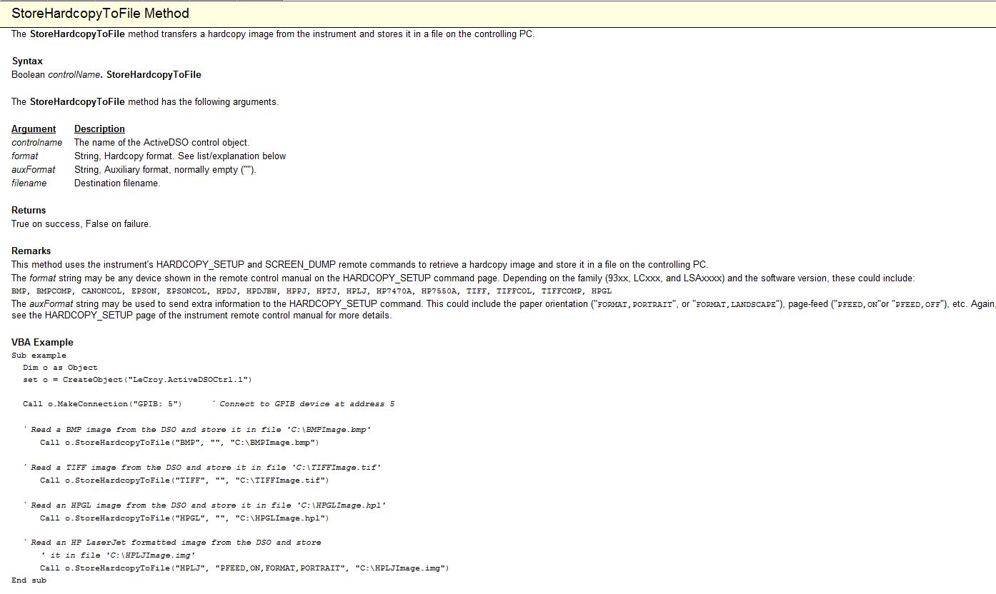
There is a method "StoreHardcopyToFile", that you can use to get a picture and save it on your PC.
Here is a picture from the help file ActiveDSO showing the method with a VBA example to use.
Let me know if you have any challenges.
Kind regards
Leonard Brown
Technical sales engineer
Teledyne LeCroy
1-800-553-2769 -
In train to build a pacemaker triggered two pulses (in burst), using the PCI-6251 M-Series card.
-
How the ND_SCANCLK_LINE signal used in DAQmx? It is complete Hold event?
I have moved an old application (using the PCI-6013-OR map) to DAQmx recently, but have some difficulty working. When starting, the signals are configured as shown below.
Select_Signal (1, ND_PFI_2, ND_IN_CONVERT, ND_HIGH_TO_LOW);
Select_Signal (1, ND_SCANCLK_LINE, ND_SCANCLK, ND_LOW_TO_HIGH);I've done the migration as shown below.
Select_Signal (1, ND_PFI_2, ND_IN_CONVERT, ND_HIGH_TO_LOW);
DAQmxExportSignal (TaskHandle, DAQmx_Val_AIConvertClock, "/ Dev1/PFI2");
DAQmxSetAIConvActiveEdge (TaskHandle, DAQmx_Val_Falling);Select_Signal (1, ND_SCANCLK_LINE, ND_SCANCLK, ND_LOW_TO_HIGH);
DAQmxExportSignal (TaskHandle, DAQmx_Val_AIHoldCmpltEvent, "/ Dev1/AIHoldComplete");
DAQmxSetExportedAIHoldCmpltEventPulsePolarity (TaskHandle, DAQmx_Val_ActiveHigh);But my application displays the data in the form of two samples shifted left. I guess that the acquisition has been delayed.
I do correct migration or is there something different in the DAQmx?Documentation OR that I get confused whether ND_SCANCLK_LINE or AIHoldCmpltEvent sample clock. Or is this sample clock?
What is the SCANCLK Signal, and how to use it?
Hope this helps
-
Hello
I want to generate the continuous signal and at the same time I want to read that signal that I generate using a single card DAQ. I want to generate signal and the received signal is synchronized and in phase.
I looked at several samples on the sync, but it quiet confusing. One using the same clock of entry while the other use a trigger to start. I use the PCI-6024E DAQ card.
Can someone help me in this regard?
In two of these screenshots, the task to HAVE started first (that's what you want, because it is the task of the slave).
Typically for AO, you can simply write a unique period of your waveform, and then regenerate again and again. Your waveform would be preset before the task starts. If you need to update the waveform on the fly according to enter programming during execution of the task, you would disable the regeneration. In addition, if the wave form is such that it cannot be easily represented by a predefined buffer (for example, it is a strange frequency which is not a same ditch at the bottom of the sample clock), then non-regeneration is the way to go.
Best regards
-
672PCI 6723 error when you try to generate a signal with the sample of 20 kHz clock
I have a piece of code that worked successfully on the PCI-6224 map, but when I tried to implement the same code on the card PCI-6723 I ran into problems.
Here is the code I use:
ManchConversion6723();//produces SendIt array of series of 1s/0s

// DAQmx Configure Clock
DAQmxErrChk (DAQmxCreateTask("",&taskHandleFRQ));
DAQmxErrChk (DAQmxCreateCOPulseChanFreq(taskHandleFRQ,"Dev3/ctr0","",DAQmx_Val_Hz,DAQmx_Val_Low,0,20000,0.5));
DAQmxErrChk (DAQmxCfgImplicitTiming(taskHandleFRQ,DAQmx_Val_ContSamps,72));

// DAQmx Configure Digital Output
DAQmxErrChk (DAQmxCreateTask("",&taskHandle));MessageBox("D");//vj
DAQmxErrChk (DAQmxCreateDOChan(taskHandle,"Dev3/port0/line0","",DAQmx_Val_ChanPerLine));MessageBox("E");//vj
DAQmxErrChk (DAQmxCfgSampClkTiming(taskHandle,"/Dev3/Ctr0InternalOutput",20000,DAQmx_Val_Rising,DAQmx_Val_ContSamps,72));

// DAQmx Write Code
DAQmxErrChk (DAQmxWriteDigitalLines(taskHandle,72,0,10.0,DAQmx_Val_GroupByChannel,SendIt6723,NULL,NULL));

// DAQmx Start Code
DAQmxErrChk (DAQmxStartTask(taskHandleFRQ));
DAQmxErrChk (DAQmxStartTask(taskHandle));
When I get on the DAQmxCfgSampClkTiming line, I get an error stating:
DAQmx error: measurements: request the value is not supported for this property value.
Property
 AQmx_SampTimingType
You asked: DAQmx_Val_SampClk
You can select: DAQmx_Val_OnDemand
Task name: _unnamedTask<0>
State code:-200077
I think that the problem comes from the variable of the source of the function. I'm just tring to send the data to the frequency of 20 kHz.
Any help would be greatly appreciated. Thanks in advance!
Too bad. The impression that the PCI-6723 does not contain correlated DIO channels. In other words, examples of clock cannot be linked to the DIO channels allowing the generation of digital waveforms. According to the AO Series user manual, this applies to the NI 6731/6733 only. The mistake was trying to tell me that only a single issue or receive channel has been authorized.
For this reason, I'll stick right with my card PCI-6224.
Sorry for the confusion.
Maybe you are looking for
-
error item not taken in charge on the RIO
We have a project involving a RIO and a WSN, that has been put together for my by a value OR added reseller. I can see the RIO and MAX WSN nodes and can connect to everything. When I look at the view of the project, I get a warning on the RIO (yello
-
HelloAm looking to find more information on affiliate programs, especially in family office. Lance a site soon that helps in the construction of PCs, OS, antivirus and other custom software where a user can withdraw its own.
-
Vista complete recovery updates
I do a full recovery, is my operating system. Vista Home premium. It is said that the window updates no longer support updates for vista, unless you have some packages of 1 (sp1). So, how do the updates? You, Ed
-
Hello- I have a HP Officejet Pro 8600 Premium who bought last week. When I left the office last night - everything was fine - this morning the control panel is completely empty. I tried suggestions (unplugging, reboot, unplug,) power outlet, etc. a
-
Photoshop lets my J - PEG record without background being white or another color.
No matter what I do, it will not save bottomless.It has just stopped working and its getting boring.