Many FPGA target as a controller cRIO
Hello!
I was reading the cRIO System Configuration Information (CRY) Encarta article (http://www.ni.com/example/51852/en/) and here the Figure 9 shows a cRIO controller with multiple FPGA targets. How can this be accomplished?
In my case, when I tried to add a 2nd FPGA target, under my cRIO-9076, I get a message that can only be associated with the controller.
Any ideas?
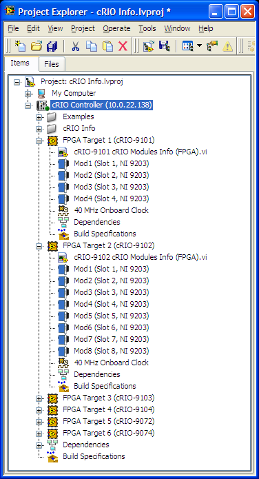
Support of claims library CRY to LabVIEW 8.5.1, which leads me to believe this screenshot was taken in this version. The RIO Scan Interface/FPGA Scan Engine (IRS) have been introduced in LabVIEW 8.6 and NOR-RIO 3.0.x. To include this support, introduced the notion of a frame in the LV (notice there is no chassis under the Comptroller in the screenshot). To facilitate the RSI and the analytical engine and provides a more accurate representation of what is actually available in a system, you can only add a frame by controller. This allows the IHR charge the correct controllers for deployment.
BT 8.5.1, you can add multiple targets to an integrated system controller/FPGA (as the cRIO-9072) even if there is no way that could happen in real life, so it's not really desirable. You can always do is to add multiple FPGA targets (even chassis cRIO) in respect of the purpose of the workstation in your project. Still allowing you to communicate with the target FPGA, but no screws will run on your PC system, not the cRIO controller.
Tags: NI Software
Similar Questions
-
Using in a project (Module FPGA) LabVIEW FPGA targets
Hi, I'm currently adding a FPGA target in the Local development computer, according to http://zone.ni.com/reference/en-XX/help/371599H-01/lvfpgahelp/adding_an_fpga_target/
Here are the steps:
- Or create a new project , open an existing project.
- "Right-click my computer in the Project Explorer window, and then select New" targets and devices of the
But I can not find targets and devices in the menu new. I have only this window (see file attachment).
Is there something to do before? I installed the FPGA module.
Thanks for your reply.
OK, but it is not necessary, I found myself. Thank you.
-
Learn how to run labview vi on fpga target
How to create a vi and execute on the target fpga on labview? What are the boxes to tools/modules required for the installation and the steps of creating a vi to execute on the target fpga
Hello Wrang,
If you want to program in LabVIEW FPGA targets, you need following:
-LabVIEW

-Drivers for supported target FPGA (OR-RIO)
-in some cases, you must have the LabVIEW Real-time module (for example to work with ComactRIO)
To start working with FPGA targets, I would highly recommend to go manual start-up of pit for specific device. In general it's pretty much the same for all targets, then you can take a look at Getting Started manual with CompactRIO and LabVIEW.
You can also find a lot of documentation or examples on our web site. For example, you can take a look at creating a FPGA and Application project.
I hope you enjoy to work with FPGA OR!
Kind regards
s9ali
-
Error: Execution of registry is supported only on the FPGA target
I am trying to write a debugging tool to test the communication between objects FP on my host VI to a RT system and then to a FPGA system. I thought I would "simulate" the three layers with queues between them in order to ensure that the parameters are received correctly - a comprehensive test of Communications virtually. I want to be able to run this VI on the host. There are a lot of bits being shifted and twisted and be able to define probes and braekpoints within a single host VI is an advantage.
Initially, it worked fine after copying my FPGA code (with object instantiation of the registers and then reading and writing for them), but now then LabVIEW did another thing that disappears (with no goodbye or anything like that). When I say that it worked, the values read from the FPGA objects that instantiate their own records showed the correct values when sending data. This means that LV really instantiate records and has been able to address them individually.
Since then, I get the error appearing in the title, whenever I try to run the VI.
(1) should I really move my parts FPGA to a VI on the FPGA target and have the VI in parallel with the defined target to run in Dev mode (and sends data over the DMA channel)
(2) why this work initially and then fail?
Shane
False alarm, I had no wired all my objects instantiated (and thus a communication VI received default objects with no valid registry.
Program actually works very well.
Still weird, but the error message doesn't really leave everything that was wrong.
Shane.
-
Xilinx FPGA target properties options is not available
Hi all... I have a little problem.
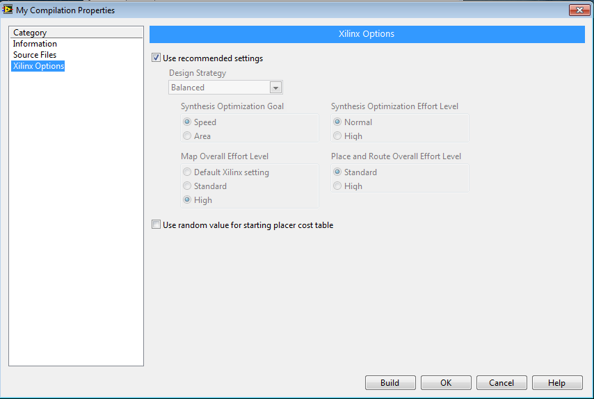
I can't have Options of Xilinx FPGA target properties to change the goal of optimization of the synthesis of area instead of the speed in 2012 of LabVIEW. Please let me know the cause and the solution to this problem.
Thank you.
Coelho,
Interesting, looking to the right place for the compiler options? Compiler options will not be under 'Properties of the FPGA target' as you mentioned previously (sorry I missed this in your first post), rather these options can be found under the heading 'Options of Xilinx' when you create a specification to build FPGA for compilation.
"" Click on build specifications ' New ' Compilation, and then select the Options of Xilinx category and you should see a window like this.
Can you confirm that you are looking at this place?
-
Is it possible to use a controller cRIO without backplane FPGA?
Of course, I'm talking about the modular units (cRIO9014 or 9025) and not the all-in-one models. If we have no requirement of IO/FPGA for an application, can we just use the controller by itself? I realize this isn't a more optimal use of this material, but it is a requirement.
Thank you
Chris
Hi Chris,
Yes, you can.
You are limited to the in / outputs of the controller itself (switch USER, USER LED, LAN Port, perhaps RS232), but you can run the controller on its own...
-
Hey Gang,
I'm trying to get a new cRIO flight for a client project. I have LV 2010 and 2012 on my computer. I've got modules RT in both. I made a project of RT/FPGA cRIO since more than a year.
The cRIO shows 'execution' in MAX. Some modules are visible in the remote Manager application. My gut tells me that the cRIO is correct.
When I try to create a project of RT in 2012, RIO Compact does not appear in the list of the types of targets, so I can't select the cRIO chassis. Selection by IP address is 'something' in a project file, but no options appear.
I tried the same thing in LV2010, and everything goes as planned, until I try to DL on the RT controller. It returns an error, something like: 'Unexpected Version of RT OS' probably a newer version.
According to me, I'm missing some software, or it is not connected to LV2012. NOR-RIO 4.0 is installed on my computer. I can see through the tree of the max software.
I wasn't expecting this part of the project to take even a day to start, so I can't wait to help. I'll appreciate any ideas.
Thank you!
Roger
Hi RogerMont,
You will need OR RIO 2012:
http://Joule.NI.com/nidu/CDs/view/p/ID/2969/lang/en
DylanC
-
Hello
I'm working on a project with several compact RIO. They each have an identical to control object (voltage, temperature,...).
In my oversight, I have a vi that must automatically seek measures based on the number of the object I want to browser.
I would like to know if pour L'Ouverture FPGA reference, it is possible to automated: according to the number determined, I connect to such cRIO and I take such file or is that it is mandatory to "write hard in Schema view all combinations?
Thanks in advance for your help.
Bastien
Hello
you are on a part of the forum in English. Please use this forum for your future poster available in French:http://forums.ni.com/ni/board?board.id=4170 .
I do not have understood exactly what you want to do. Can you explain a little more the structure of your project (various screws, target,...).
I just see this post:
http://forums.NI.com/NI/board/message?board.ID=4170&message.ID=34299#M34299
Is this the same problem?
Kind regards
-
FPGA target 9146 OR editions variable defined by the user to a network
I am developing code to use on the expansion chassis NI 9146 ethernet with 3 hanging modules, NI 9205, NI 9264 and NI 9476.
The code is supposed to be downloaded on the chassis as FPGA code and run the code itself and the release of information on the network for the chassis, it is hanging in. The code is simple (blood pressure measurement and convert them to pressure).
When the code is on the host pc, it can be run through the target and runs correctly. The pieces are just have thing chassis user FPGA 1 LED blink a few times per second, convert the voltage in pressure and variable output on the network and read some Boolean variables that are on the network. All variables are not listed in the network in this way (by pressing the button run an FPGA VI compiled host) by pressing
When the FPGA VI is downloaded to the flash memory chassis, configured to run once downloaded and restarting the device, the VI FPGA runs, because user FPGA 1 LED flashes on the specifided rate in the code, but variables do not put on the network.
Attached are several screenshots of the code window and screen project.
Thank you for your time
Mitchell
Hello
The FPGA cannot write to the variables by itself. It is usually used to make a task of high speed. In order to communicate with a host computer, you will need the code running on the controller that uses screws FPGA Interface.
-
Hello
I recently installed a NI PCIe-7852R in my computer and I see that the card is installed in the max of NOR. However, I can't possibly configure it somehow or max.
Also I'm unable to add this card as target during the creation of a project. In fact I do not see the possibility to add new targets and devices when I right click the icon of my computer in the Project Explorer window.
I'm using Labview version 13.0.0, module FPGA 13.0.0, NI RIO version 12.1.0
Any help will be appreciated.
Thank you
Gaelle
Hello gaelle
You may need to upgrade your version of NI RIO, you should look at this table of compatibility related: NOR-RIO and compatibility of the versions of LabVIEW.
Here you can find: NI RIO 13.
Concerning
Frank R.
-
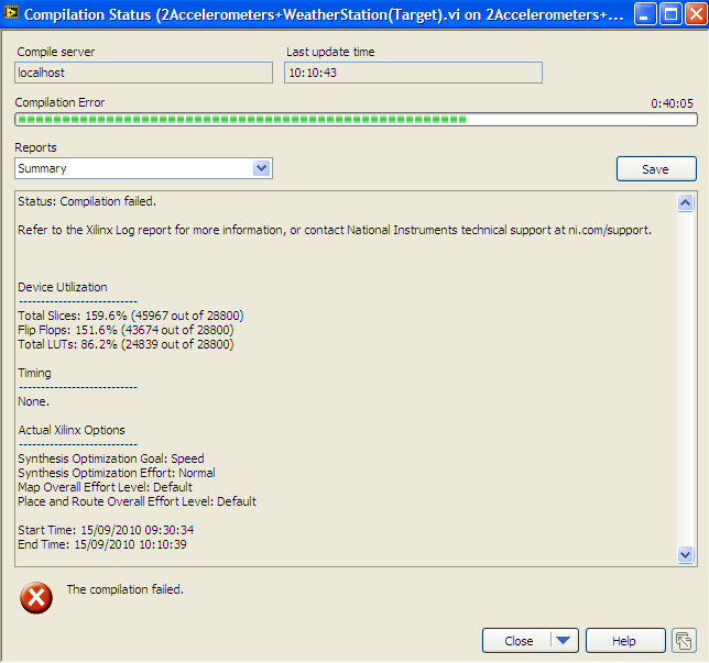
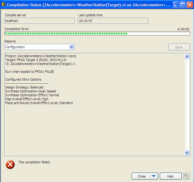
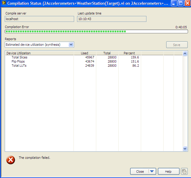
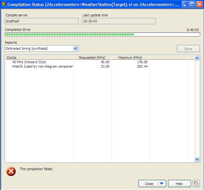
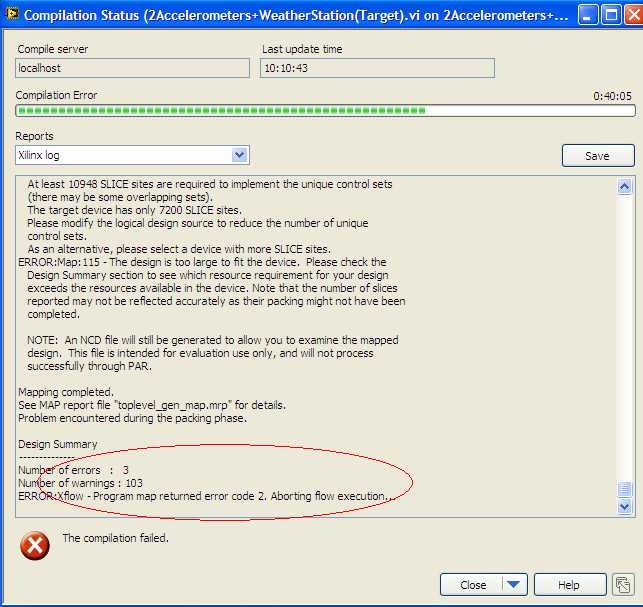
Failure of compilation of the FPGA target
Hi all
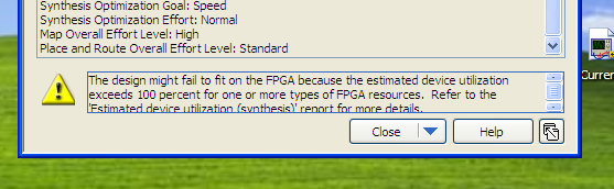
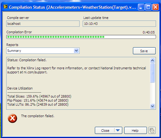
I met a problem when I tried to compile my target FPGA VI. Failed to compile for some reason any to halfway after start of the compilation. I post a few screen shots of the labview error information.
What causes this problem? How could I solve this problem?
Thank you very much!
Kind regards
masterwho
Also you have large networks on the Panel before the FPGA VI?
Or is there the great paintings inside the code?
If you can, put a piece of your code.
-
Disable the extended FIFO FPGA target during execution
Hello
I use a FIFO extended target in my FPGA to constantly calculate the derivative of a measured value (dB/dt). Thus the FIFO stores all values during time dt. This means dt determines the number of items in the FIFO and dB is determined by the actual value less the oldest value in the FIFO. It works well when I initialize with the code in figure InitFIFO.
But the FIFO of compensation is not possible (see figure clearFIFO). In the while loop if "reset dB" is false, as the new value of B is written on the FIFO, then the oldest value is read from, for the number of items in the FIFO remain constant. To change dt during execution, I need to clear the FIFO and initialize it with a new length (number of items). I tried the next loop, but it does not work. The FIFO does not initilized with the elements. The length is zero and the loop counter for (#deltaB Length2) is 0.
What I am doing wrong? Is there a better way to erase a FIFO during execution in the FPGA? I'm now stuck for 2 days with this problem and looking forward to any idea or suggestion.
Thank you very much. Best regards
Andy
Hej,
Thank you for your response. You were correct, that deltab FIFO length was 0 because the defalt value was zero. The problem is that in my host vi on the RT system I put DeltaB FIFO length in a loop of high priority and as you can see when I restart the FPGA, DeltaB FIFO length has a valid value (the code in figure 1 works well with a local variable of DeltaB FIFO length in the FPGA). But the variable to set the variable "reset dB" is under the control of the loop of low priority of the host vi. And there, I had an entry DeltaB FIFO length unwired.
So, I learned that a control FPGA read/write unwired sends a '0' or resets the variable to its default value in the FPGA. I assumed that nothing is transferred and the last variable is retained if you let a control read/write unwired. Now, I learned of this stupid error!
Thanks a lot again!
Andy
-
Compilation of FPGA 61330 error on a cRIO
Hi all
Currently, I have to rebuild a fpga bitfile to reflect a new hardware configuration on a cRIO. I have installed on my computer, tools that have been able to compile the bitfile several times; but now I get an error when I compile. I have attached two images of the error to this message. I'm currently under this software configuration:
It turns out it was a firewall issue. I had turned off my firewall, but there was a tertiary process still running. I added a few my firewall exceptions, which should allow the program to work, but it didn't. Once I deleted these exceptions, the compiler run with no errors. I think it's time to get a new firewall program. Thanks for all your help.
-
FPGA target host DMA FIFO multi-channel
Hi people,
I have a little trouble to collect my FPGA application data. The control of my FPGA application loop is running and read data from set point between a host and target FIFO to a period of 50 uSec. I run a separate loop to write data collected form two channels in a target of FIFO host over a period of 1000 uSec. I'm taking the data from both channels and its reading on the host in bundles of 500 data samples. The first problem I have is that my method of reading times unless I put my data acquisition loop to run at a much slower pace. My FIFO depth host side is 60000, almost as large as the total number of data samples that I expect to collect in total.
I have another problem when trying to write the data to a table. Even if my method of reading does not expire, I don't think that will record the first beam of data that are read. I've initialized an empty table outside my acquistion of the side loop host and used the table VI build to take the current data set and add it at the end of this table. I then store in a shift register and pass it in the next iteration where I try to join the new data set to the old and so on. I expected to get a table with all the data, but as I said I'm only collecting the first set of 500. I wonder if my program structure is correct. Any help anyone could offer would be greatly appreciated. I have attached a few pictures of my reference request. Thank you.
Hi Daniel,.
Thank you for your response. I think I found a solution to the problems that I had. Looks like it was a combination of a couple things. First, the data acquisition loop was running not until the movement was already over since I plugged the condition to stop the loop of writing deposit directly on the data read loop. This problem has been fixed by creating a shared variable for the stop condition and it wiring to two loops independently. This explains why I got only the first set of data, as it was stored in the FIFO until the end of the movement. However, the FIFO of feedback was still time. Before attaching the stop condition error, I placed a probe on the "items remaining" wire of the read method and concluded that there was only 1023 elements (the depth of the FIFO on the side FPGA) even if I set the FIFO depth host side to 60000. "» I realized it was originally due to the Read method not called for the first time until the end of the movement. Although the problem of break for most fixed condition this problem given that the Read method was now called during the movement, I decided to take a preventive measure and calling the 'Start' before the movement FIFO method is started just to make sure that the memory of PEP on the side host is available immediately.
So yes, it turns badly I put sync settings have been well after all. Good call on the reversal of the order on the Array function to build. Oh, and I also had to move the waveform diagram to until the table is built so that it is not Replot the old data on top of all the new data it receives. On the same note, I moved to the indicator in table at the end outside of the loop of reading. Thanks again for your help.
Kind regards
John has
-
Demultiplexing FIFO on FPGA target
Hello
Is there a 'best practices' for the multi-channel DEMULTIPLEXING from one host to target FIFO in an FPGA? All of the examples I can find only discuss multiplexing on the FPGA to pass multiple channels of data to the PC, (the scenario of "reverse") who seems simpler.
On a related note, is it possible to play more than one sample of a FIFO by clock using parallel FIFO read nodes?
Thank you
"what interlacing out side of FPGA should look like a chart, and if there is a favorite answer"manual"
Have a separate loop off interlaces the data and transmitting values to individual single channel FIFO is a very common model, enough so that I would say you usually want to start with this approach if each channel can be treated individually (i.e. in parallel with separate loops).
If the strings must be addressed together, then it is more common to have a loop that creates a single table for each set of samples of channel and then passes this array by a simple FIFO to the processing loop.
In both cases, the control FIFO logic must maintain the flow correctly as long as you use indicators of exceeding time limit or the handshake correctly.
Maybe you are looking for
-
Records show new messages, but there is no new messages in the folder
I have used filters to set up the folder called application, which I used for several months now, all of a sudden I have a problem with one of this file see the new messages, but there is no new messages in the folder. I checked with my email provide
-
Fire, which is also called little panda, Fox belongs to Caniformia. (http://www.mozilla.org/projects/firefox/firefox-name-faq.html)Mascot on this page: http://www.mozilla.org/en-US/firefox/new/ is a fire Fox. But one that is used in your icon is appa
-
THE LINKS AT THE TOP OF ANY WEB PAGE NO LONGER WORK. What COULD BE CAUSING THIS
IN THE LAST DAYS ANY WEB SITE I GO TO THE LINKS IN THE BANNER OR THE UPPER PART OF THE PAGE DO NOT WORK. THE SYSTEM DOESN'T SEEM TO KNOW THAT THEY ARE LINKS WHEN I HOVER OVER THEM, I GET THE ARROW OF THE MOUSE INSTEAD OF THE HAND ICON LIKE I DO ON AL
-
Skype GUI is not loaded correctly.
After installation run Skype on Win7 GUI of Skype is not correctly loaded. It looks like image below. Can someone help me?
-
Impossible to find some drivers
Hello After validation and get help to find most of my drivers,. I found that there are always a couple that I or my computer can find, specifically, the marked device drivers PCI device and 2 USB controllers, SM bus controller and then another that