MAX how to acquire data only on hardware triggers?
Hey,.
I need to use the card pci-6224 daq material being triggered. Here's what I did: -.
(1) I put these settings in the configuration affecting changed my acquisition mode 1 sample (timed HW) and set the rate at KHz
(2) the digital edge trigger type, my pfi pin and the whole edge to edge down
and here is what it does Max awaits the first impulse before data acquisition and after the first impulse, he always keeps the information even in the absence of triggers. I used an oscilloscope to see if I was generating pulses in my pfi of entry but there is no generated impulses.
So I was wondering if someone could tell me a few reasons as to why MAX keeps getting data after the initial outbreak?
Thank you
MUGA,
To make an acquisition redeclenchables, we need to set a property that we do not have access to directly to MAX (redeclenchables true parameter). However, based on what you have explained, it's pretty simple applications you meet. The best way to proceed is to simply use your trigger as an external sample clock signal. Using this trigger as the sample clock signal, you will take only sampling points on the edges of this signal trigger regardless of the trigger parameters. So, I simply specify this signal as your external sample clock and go from there.
Timothy
Tags: NI Software
Similar Questions
-
How to acquire data from the memory of the meter
I am a beginner of Labview. I don't know how to acquire data from the memory of the meter.
I read a few examples of data acquisition, but apparently not similar to my case. I can't use DAQ in my computer, because I don't have DAQ card.
Could someone give me some pointers? Similar examples would be great.
-
How to acquire data through several channels in parallel using E 6070 PXI, PXI-4071 and LabVIEW?
Hello
I use LabVIEW and NI PXI-4071 PXI NOR 6070E to measure the current through a variable resistance. Now, I use a single channel of SCB - 68, but I want to add another channel at the same time so that I can have two resistors instead of one that I cam measure current through them.
I have attached a Pdf file showing installation of equipment to use and code LabVIEW also.
Can someone look at these files and give me some guidelines or ideas that can help me solve this problem, please.
Thanks in advance.
Best regards
Shaheen.
Your 4071 can do a measure at a time. Your data acquisition cannot measure resistance is not she of the analog inputs.
However, you could use a multiplexer and multiplexer your 4071 DMM. This habit give you simultaneous action, but can acquire data one after the other, the speed depends on the multiplexer, you choose!
I hope this helps.
-
How to acquire data from both channels on a PCI-5922 (OR scope)?
I'm fairly new to LabView (version 8.5.1) and I'm working on my first vi non-teaching. I need to acquire analog of the two channels of a PCI-5922 data. I made a single channel using NEITHER brought Express, but you can use NOR carried Express to both channels. I tried two instances and that left me with a free entries or exits, I also tried to allow the two entries, but I get only one exit. I think that I don't have my head in the right place with this. Sorry if this is very basic.
Thank you... Steve
Take one of the LabVIEW base tutorials.
Simply use the Signal from Split. Of course, it's always this evil dynamic data.
-
How to acquire data collector output open.
the output data that comes from a single thread of the instrument without the signal ground of the instrument, IE, open collector output data. which is the least expensive and best hardware OR data collector output open?
Cross posted the LAVA:http://lavag.org/topic/16327-acquisition-of-open-collector-output-data/
As I said in the thread of the LAVA, there must be a reference to Earth somewhere. Now the question is that you try to measure the voltage output or the status of the output?
-
Using asynchronous calls in a while loop. How 'Skip' node and only retrieve data as it is treated
Maybe I'm not understand asynchronous calls... but I thought I should be able to call one another VI and essentially 'jump' it is the node and only receive data as the called VI treats. In other words, similar to the Run of VI, I can wire a wait until done? with a fake and the main VI will not wait for the other VI end of race. The main VI continues to function, and when it passes the called node of the VI, it will receive data if it happens to be there.
How can I call a VI in a while loop and do not wait so he could spit out the results? Data flow is my enemy on this one...
The first VI treats its own figures (using the iteration count) and displays them on the PC. Other indicators are the data of the called VI. I want to be able to work around the blue circle node and receive data only that it will be available.
Any help is appreciated. Thank you.
What I said OR the 'Start asynchronous call' is the preferred method for starting background tasks. This call is usually used to run background tasks. For example, you have a process of journal. When your application starts it would use the "asynchronous call Start" to start the process of journal and then move on to the other stuf. The process of the journal would then happily run in the background and the main application is free to do other things. Of course when implementing these types of systems you need a way to coordinate things like exit. This is where the queues and stuff come it.
-
How can I use only cellular data then a Wi - Fi network?
I don't want to use the cell data only when the Wi - Fi connectivity is poor (for example turn on help Wi - Fi), I want to use cellular data 100% of the time. Why, you ask quite rightly? Because I have a data plan unlimited cell phone and I just want to play the channels of information and Netflix on my TV via AppleTV using AirPlay.
AirPlay is only active when connected to a Wi - Fi network. I don't live anywhere near fixed services of any kind. I would watch my Netflix or other video services on my TV rather than on small screen of my phone.
Are there any combination of parameters that will allow me to achieve this goal?
Are there any combination of parameters that will allow me to achieve this goal?
Sorry, but no. The Apple and Apple TV routers require a wired Ethernet connection or a standard Wi - Fi connection.
You can take a look at a router 3G / 4G... something like these for example:
http://www.TP-link.com/en/products/list-4691.html
Good idea to check to make sure that your provider supports supported router before you buy if.
-
How to load all the data without uncheck Journalized data only option?
Hi all
Currently, I have configured an option only logged data for many game data and interface.
But I need to load all the data (once) without clear logged Data Only. After that it will work with the CDC.
Please help me on this.
ARO
EBAHi Eba
Another way is to copy the source data to another table (two copies).
If you have 10 source table and then create another 10 tables in doubles in the backend.
Now truncate these original paintings. Then insert the data in table duplicated in the original table. Now CDC will detect these are inserted.
But I guess you have more than 300 paintings, which is again difficult to manage. -
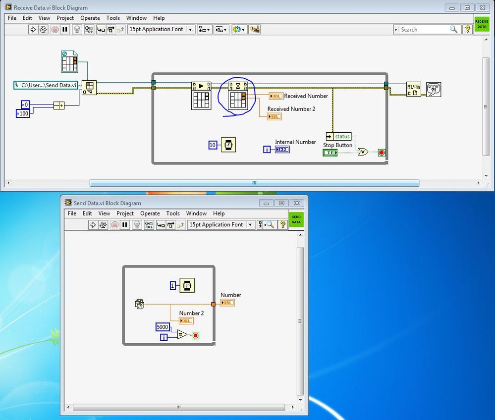
Get the highest value of acquired data
Hi, how can I get the highest value of data according to data acquired using the accelerometer ADXL345 and LINX in LabVIEW?
I want the highest data to be shown with a flag. However, the data being shown are always the last acquired data. My problem would be what happens if the highest data somewhere at the beginning or in the middle of all the acquired data? How to display the highest data using an indicator?
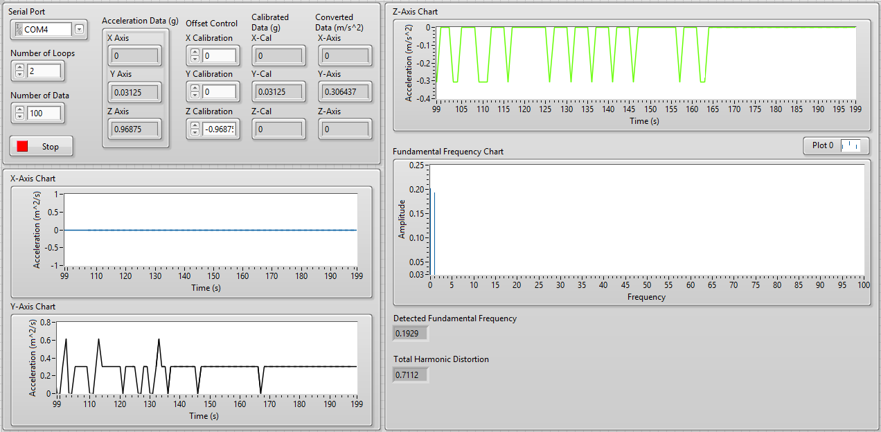
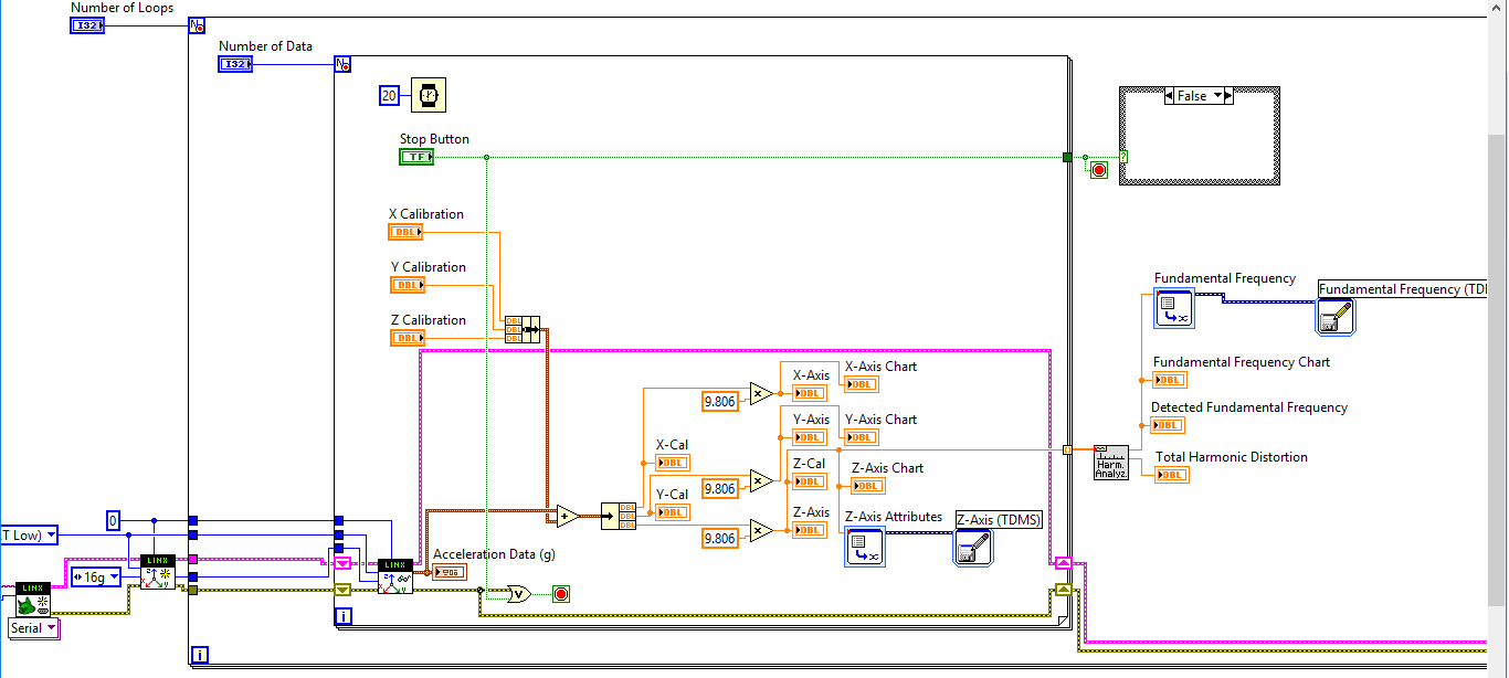
Here's a look at my front, block diagram, and sample of the acquired data.
From the front panel, the basic indicator of detected last poster 0.1929 (amplitude), which is the last value. But looking at the Excel file, the highest data are data which is 0.2013. The highest, I want to be displayed on the indicator not the last value. How do I do that?
Thank you!
I gave you an example of what you need to do - it is not okay if wire you the new value and the old value for the X or Y - it will always return the maximum of the two values so the order doesn't matter. It would have been more useful if you had posted what you tried the max & min. You need a registry to offset inside the loop (like I did with my while loop). If you only want to display the maximum value for each iteration of the loop for external, you must initialize the shift register by plugging a 0 to its terminal on the left. A shift register her pinned the value of the last run - probably not what you want here.
-
How to collect data on the programs of LabView and VC ++ at the same time?
Hello
There are two programs in LabVIEW and another is in VC ++. The two programs to collect hardware data.
Therefore, for the experience, it is necessary to begin to collect data at the same time and lag must be
less than millisecond (it is essential for the experience). How can this be achieved? BTW, I'm new to LabView.
I think on the use of network socket to get the message for both applications.
I was wondering if there is a better way.
Thank you.
MARK002-MAB wrote:
Hello
There are two programs in LabVIEW and another is in VC ++. The two programs to collect hardware data.
Therefore, for the experience, it is necessary to begin to collect data at the same time and lag must be
less than millisecond (it is essential for the experience). How can this be achieved? BTW, I'm new to LabView.
I think on the use of network socket to get the message for both applications.
I was wondering if there is a better way.
Thank you.
You do not say if two programs access the same material, but I guess not. Because if they did, you probably get conflicts when the two programs try to access the same material at the same time.
In either case, the only really reliable way to ensure that your needs of< 1ms="" would="" be="" hardware="" triggering.="" one="" hardware="" unit="" is="" programmed="" to="" provide="" a="" hardware="" trigger,="" typically="" a="" digital="" signal="" and="" the="" other="" is="" programmed="" previous="" to="" the="" desired="" start="" point,="" to="" wait="" for="" that="" trigger="" and="" start="" automatically="" when="" it="" is="" received.="" if="" both="" hardware="" units="" are="" ni="" daq="" cards="" you="" can="" do="" that="" fairly="" easily="" using="" the="" rtsi="" bus="" or="" in="" case="" of="" pxi="" the="" pxi="" trigger="" lines.="" if="" they="" are="" different="" hardware="" then="" it="" can="" get="" more="" complicated="" to="">
-
acquire data from the oscilloscope DPO2024
I am trying to acquire data from the oscilloscope DPO2024 using labview. I am able to do, but my vi file only works for channel 1. Other than channel 1, it does not work and instead, it changes the adjustment of the oscilloscope as well. Find the vi files attached.
Any help is very appreciated.
You must connect the channel in the waveform of reading. It is default to channel 1 if thread continues.
-
How to acquire of various AI channels simultaneously with a different range for each of them?
How to acquire of various AI channels simultaneously with a different range for each of them?
In LabView, I found some examples but in C it is not seem to be any.
Or you can add channels one by one with individual instructions: the follwing code compilation and runs without error on vitual DAQ hardware:
ERR = DAQmxCreateTask ("", &taskH); ")

ERR = DAQmxCreateAIVoltageChan (taskH, ' Dev1/ai0', 'AI0', DAQmx_Val_Cfg_Default,-5,0, 5.0, DAQmx_Val_Volts, "");

ERR = DAQmxCreateAIVoltageChan (taskH, ' Dev1/ai1', 'AI1', DAQmx_Val_Cfg_Default,-10,0, 10.0, DAQmx_Val_Volts, "");

DAQmxStartTask (taskH);

ERR = DAQmxReadAnalogF64 (taskH, 5, 10.0, DAQmx_Val_GroupByChannel, val, 10, & read, 0);

DAQmxClearTask (taskH);
-
How to read data from OM - 62 temperature/humidity data logger in LabVIEW?
Hello
I have an Omega OM-62 temperature/humidity data logger I want to communicate (initialize recording, reading/writing data, stop recording) through LabVIEW 8.6. The OM-62 is connected to the PC via a type B USB-miniUSB connector, and I have provided "Omega Recorder program Interface" on my Windows operating system. I called online DAQ support Omega but I was told that data recorders low level like this have not provided capabilities of LabVIEW, which I fully understand.
My question is why I have to use their program to communicate to this device? If I knew the syntax program them used to connect to the device, why can't I use through VISA? Do I need to build my own LabVIEW driver from their supplied driver?
Python is easier to apply to this scenario solution?
How can I see the code "Omega Interface Progam recorder" on my Windows operating system is using to communicate with the OM - 62 sensor?
I just want to know how this could or could not work because I think I'm missing some concept in my understanding of programming LabVIEW/novice. It would be easier to run my LabVIEW program and their program at the same time, but I just want to understand it at a deeper level.
Curosity killed the engineer occupation,
Zach
P.S. I have attached a few driver configuration information, but I have no idea if this is useful.
Unless the manufacturer provides a kind of programming interface or API to communicate with the device that you have trouble with your own software interface to it whether LabVIEW or Python or something else. This could be in the form of a driver dll, Protocol series modbus (etc. etc. etc.).
If it is not condition / available and you really need to communicate with the device, you will need to look at using something like a sniffer USB/driver (software? hardware?) to try to intercept communications between their software and the device. You can then use this information to try to understand what the commands it sends and the responses received and how to convert data.
Once you have that until now... I don't know what options are willing LabVIEW for control of USB device, but a proposal, I would say that you would need either a driver USB low level or you have to write your own driver in another language and that call from LabVIEW.
-
I need to transfer a voltage using a PXI-5421 signal before a Council of PXI-2576 and then transfer it to an another Committee of the PXI-2576. For example I had set the signal of the ARB has then put 16 CH MUX 1(1st Switch), the value CH MUX 3 0 (switch 2) then read the MUX 3 voltage using a PXI-4071. I know that I can use the example of DMM Switch Handshaking.vi niSwitch for the rear. I'm just not sure how to transfer data to MUX 1, MUX 3?
Thank you
Denise Barajas
Hi Denise,
You must connect two switching modules to the outside. Signals may not actually be transferred through the PXI chassis backplane. Bottom of basket can only be used for communication by PCI bus and for the delivery of the trigger. You need to use external threads to physically send the signal of the first PXI-2576 to the second.
There are two ways to connect signals to the PXI-2576, you can use a block of endings that mounts to the front of the module PXI, or you can use a cable with a block of external connection. You can then connect the signal cables to the connectors to screws on the terminal/connector block. More information about the options of connection to the NI PXI-2576 connectivity products Page.
Hope this helps!
Chris G
-
HOW TO READ DATA SERIES WITH SYNCHRONIZATION
I have a question about my application for the acquisition of data in series. In my application, I use visa read to acquire data series sent by an inertial measurement unit. When I first put the sensor, it sends data in the following one time format:
1:0 x 8011 header followed 1 data word for Adler, 1 data word (each 16-bit word data).
and the sensor then starts sending the data in the following format:
2:0x7FFF header followed 1 data word for checksum, 9 data word (each 16-bit word data).
(Note: checksum is defined as a 2s - complement of the sum of 16 bits of the rest of the entire message)
In my application, to simplify the problem, I use a wait function to ensure that the initial data header 1 tag is sent. Then I start reading using VISA Read 20 bytes (header 2 more words of associated data are 20 bytes), as I'm mainly interested in the data header 2 tag words.
However, when I do this, the data that I get do not begin by 7FFF character and, accordingly, my 20-byte data cannot be parsed correctly. My question is how can I do the "VISA read" block read the serial port when data are preceded by '7FFF '. Once I have solve this part, my strategy will be assembled data read 20 bytes (including the header of 4 bytes) and analyzed accordingly.
Another question, I wonder if you can tell me how to use the given checksum it is defined as "a s 2 - complement of the sum of 16 bits of the rest of the entire message". Note the data that contains the header 1 tag is 1 post.
I would appreciate if you have responded to my request.
Thank you!
Serdar

Maybe you are looking for
-
How can I create a user account: username and password?
I'm trying to transfer bookmarks Firefox from one machine to the other. I need an account to identify bookmarks I want, but as far as I know, I do not have an account of Firefox. So I try to create one on the old machine that I use to transfer bookma
-
No squint should display the percentage of zoom on the toolbar state of RL. It's noty
I wish it works
-
Zbook 15u: AMD GPU on Zbook 15u not used with Windows 10.
I have recently upgraded to Windows 10, downloaded and updated all readers. No matter what I do, I can't do GPU AMD do any work. its always at 0% in any program, I use Adobe Premiere or DXO Optics. It worked fine on windows 7. I am not getting any e
-
not able to scan in windows media player
I can scan in the paint, but not in Windows media player, I use windows 7 64 is the HP Photosmart C3180 printer
-
Good morning, members of the community. I'm having problems with the behavior of SkyDrive. I use it to download shared files I change on different sources and different places. In addition to the information very important (date and time of the last