Measure the frequency of the pulses PXI-6624
Hello. I work with a PXI-6624 and am interested to make measurements of pulsed frequency for frequency and duty cycle on its inputs using DAQmx.
When I go to create the virtual channel, however, I have error-200431:
"Physical channel selected does not support the type of measure required by the virtual channel you create."
' Asked the value: pulse frequency.
«You can select: frequency, period, pulse width, period of Semi, separation of the two edges, Position:...» »
Is this card really not capable of doing these measures of pulse frequency?
Yes, the "Pulse" (not to be confused with "Pulse Width") measure was introduced with STC3 of OR including CompactDAQ and X series devices.
Measuring the pulse:
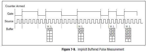
However, you should always be able to measure the frequency and the duty cycle on your card with a half measure:
The half measure:
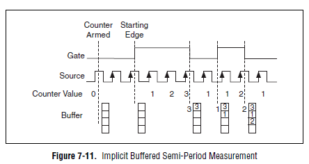
The images are in the X Series user manual.
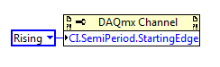
The difference between these two modes boils down to how the data is stored and implemented in buffer on the map - with the period semi method that the material does not distinguish between high and low samples and puts everything in a single buffer. However, if you start the meter on the song (see below the node property), then you would know the order of low and high samples in software, and are easy enough to calculate cycle frequency and the duty of this.
Best regards
Tags: NI Hardware
Similar Questions
-
at the same time production and measuring the pulse
Hello everyone,
I'm generates a pulse for specific time. Now, I want to measure within the same daq card. I've done Vi for him but he has an error. I have USB daq-6343. I enclose my Vi here.
The problem is I am able to get pulses generated at PIN 6 PFI but reading Vi watch time-out error.
I plugged the wire between PFI 1 pin and PFI 6 pins on the DAQ card.
So please suggest me what to do to eliminate this error.
Thanks & best regards,
I just looked at your original vi, I had looked only at the most distant (corrected) a previously. I don't see a good reason to read timeout error you have immediately. Record of an error timeout on your attempt reading suggests that the code was executed without error so far, including the beginning of the generation of pulses. That would leave wondering on physical cable connection or possibly some undesirable side effects caused by your cleanup code when you three States a PFI lines.
The other issue was my suggestion to leave DAQmx Timing.vi outside of the configuration string entirely for cases like this where you only want to build a single pulse. To be honest, it's a habit & practice I adopted a long time ago. I thought one of the reasons was that the finished pulse trains required a minimum of 2 samples. A bit of test code showed me that it isn't true, if my memory tells me there was a time when it * used * to be true. I don't remember if I have errors or if the task has chosen to generate 2 pulses with just a warning, or something. I just remember that, while he was working on a module that was supposed to be able to produce any number of pulses from 1 to N, I found that I wasn't actually able to support the case of 1 pulse by asking just 1 sample over sample mode.
* Anyway *, the other reason to avoid sampling over for a single pulse mode is that in the past, this would consume actually 2 counters on DAQ cards. Generated the pulse (s) while the other was a help that triggered the first to control the number of generated pulses. It was unnecessary as you could * also * generate a single pulse leaving the DAQmx Timing.vi out of the config, a method that used only 1 meter.
X-series cards (like yours) don't consume over 2 programmable counters of the user to generate finite pulse trains, so the lesson I learned a long time ago and was trying to convey is perhaps not so important in your case. I recommend it even if you know that you will always generate a single pulse, simply because he considered the standard way to generate a single pulse (as seen in examples of navigation).
-Kevin P
-
Hai all the...
I'm using the port Usb-6009 meter to measure the engine for each 0.1 s and save it in the file lvm. Aquistion and and logging of data at the initial stage say 10 minutes generated pulse is acurate and data is stored for each 0.1 s, after the 10th minute acquistion speed and recording speed goes slow and instead of data for each 0.1 s acquisition it measures for 0.12,0.14,0.16, and... 0.2, 0.3 S... and stores. For this reason, I'm bored n number of impulses and I could not provide appropriate time resolution.
After analysis, I found that the acquisition depends on material used and the system used.
My System Configuration is
Intel core 2 Duo processor
2.67 GHz, 1 GB of Ram
anyone can suggest a solution for the above problem, is there another way to measure signals without loss or delay. ?
Check the attachment. You can get an idea.
-
-Measurement of the pulse width specifies the timeout?
I'm trying to set up a simple project of Signal Express that measure the pulse of two separate signal lines width.
My PCI6224 has two entrances of meter and then run each pulse in the entrance of a meter line, respectively.
The I set up the express project signal attached, which consists of two simultaneously runnings tasks DAQmxAcquire. Each of them is set to measure the pulse for one of the pulse width. I then connect the results for further analysis.
This configuration works very well from time to time. The problem arises when the impulses do not arrive quickly enough and the acquisition of the timeout action. Looks like that has a simple solution - just increase the time-out - but I can't find a single setting around the affects, the time-out! The time-out period is always 10 seconds, regardless of what I do.
Can anyone help?
Thank you.
Hello rothloup,
Unfortunately, there is no option to change the time-out Signal Express for a task entry counter. This has been brought to the attention of our developers.
Reading a DAQmx LabVIEW VI has a time-out node you can specify the time-out period, even in the tasks of meter. I suggest you try to implement your system in LabVIEW (if you can).
Here is a tutorial on how to make PWM in LabVIEW.
http://www.NI.com/Tutorial/2991/en/
See you soon,.
-
Hi all -
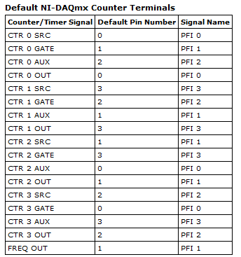
I have a request that I need to use a meter, we chose PXI-6624. I'm really good with the rest of the material, apart from FPGA and RF meters are only lines that I've not used. I'm running into some difficulties to understand how to configure my son on the 6624 and thought I'd ask here.
I have an optical sensor (Monarch Instruments model ROS) that I'll have to watch the impulses on. Its got 4 wires coming in the distance, a commune, a signal, a + V excitation (10V) and cable shielding (IE common). I am also connected to an SCB-100 using their 100 flex cable.
The thing I'm getting hung up, each meter on the module has 10 terminals assigned to him. I continue to go through the manual, but I can't understand. Went to NEITHER and the engineer he basically just copied and pasted the same part of the manual I did not understand. If you ask for more details on the portal + / for example, the response I got was 'you can if you want to signal that you are using the pins of the door the door '... I guess that means that you can use these pins as a switch to take the signal or not, as you would the door on a FET used as a switch. Just one example of how detailed responses are :-)
In any case, I am reading and looks like each entry almost has multiple functions that overlap, but I'm unable to digest it. Can someone help with the wiring on this?
Cordially - in the short term, I have 1 sensor which will include rpm for 1 pulse per turn. We also want to make direction which will need a second sensor with the set of two upward slightly as the squaring function requires. Only two will have only 1 pulse per revolution, rather than an encoder with say 120 pulses per rev. Should subsequently over them both, but I think that if I can figure out exactly one that I can use it to understand the rest of the installation on my own :-)
Thanks a bunch!
External connections:
Commune of sensor connected to the source - meter
The connected sensor signal to source + meter
Any signal of door that you would use for this application would be generated internally by using another counter and then routed internally to the door of the counter which counts the external pulses. In this case the door signal would provide a specific window of time count impulses. An example could be measure RPM. If you decide to measure the pulse for a full minute, with accuracy what a minute? If you do not exactly one minute, your RPM will be incorrect. Calendar of the software will not work.
-
Measurement of frequency triggered? NEITHER 6259
I'm trying to work out how to implement a measure of frequency (of a pulse train) which will be triggered by another external pulse to a different channel.
I have an encoder that is attached to a rotating shaft, that generates square pulses 5V on two different channels: the first string gives one pulse per revolution of the shaft (my planned trigger pulse), the second string gives a pulse all the 1/2500th of a revolution (IE all 0.144º)
Seeing a pulse of "channel one" (the pulse of a time-by-rev), I want the system to begin to measure the frequency of the pulses on the 'two way '. This isn't the average frequency during the ENTIRE revolution I'm after: what I'm shooting looks more like an angle vs revolution frequency waveform graph, for a ride (IE with 2500 data points).
It does not matter if the processing time means that the system of "lack" an impulse to start on the next revolution, because it can always wait for the next. The most important thing is that the beginning of the frequency measurement is triggered at the right time.
So far, I have used L'Express VI/DAQ Assistant to implement a measure of the frequency of the pulse 0.144º: I'm wiring these impulses to PFI9/CTR0 of Council 6259. I used a continuous acquisition of 2500 measures. The expected frequency range is about 40 to 200 kHz (2500 pulses per rev at between 1000 and 4000 RPM.)
That works very well, and I can establish a curve of angle vs. frequency of revolution, BUT... For now the beginning of the acquisition is completely arbitrary; That is, it starts when I type 'run '. I can't understand the best way to trigger the acquisition of the OTHER channel impulse.
There is no external trigger options in the DAQ assistant page, so I wonder if this is still possible using an express VI - do I have to use lower level stuff?
I am convinced that this should be easy!
Thanks in advance
Theo
Rico, Brad,
Thank you very much for your comments, I'm pleased to say that we have sorted in the end.
The first question concerned the fact that the Board I was using (PXI-6133) is not able to make a measure of frequency of trigger in this way.
It was a big problem because even if the LabView code was right it works always, leading me to doubt the code and become even more confused! However, using the same code on a Board 6259 worked like a charm.
I used the DAQmx blocks to set up a channel to measure frequency and a trigger, set the shutter button using the property with an arm.start node as in your example.
Thanks again for your help!
Theo
-
Measure the resistance with PXI DMM 4072 on different frequencies
Hi all
I tried to get on board various and unable to find solutions for that. I'm trying to measure resistance using NI PXI-4072 on frequencey 1 kHz, but not luck. When I try to use Agilent LCR meter I see the correct value of the resistance.
I've seen a few posts on this but don't have no satisfactory solutions.
In above post, someone said that I can use 4072 DMM OR digitizer, does not have a lot.
Can someone please provide the right path for me to solve this problem.
Thank you
Hello Puneet_K,
I checked the data sheet and the method of measurement described in the specifications of the NI 4070/4072 http://www.ni.com/pdf/manuals/371304g.pdf; indicates that the ability is measured using an alternating signal and select the test frequency range, for example 3 kHz, 1kH or 91 Hz. The resistance is simply measured using a DC signal, and it is often sufficient to measure the internal resistance of a battery. If you need a more flexible control for the measurement, you probably get a card like the function generator and then set a multimeter to measure the voltage and another DMM to measure the current and calculate the impedance of these values.
I hope this helps!
Kind regards
-Natalia
-
Measure Z to a battery encoder encoder pulse frequency to measure the speed using a 6034 E card
Hello
I want to measure the speed of a motor that has an encoder to encoder hung on battery. It provides impulses 3 A, B and Z I uses a PXI 6034 E card. I wanted to know if there are any examples/ideas that could help me with this (I'm new to digital programming in Labview). I moved to NI Daqmx 9.8 recently of the old version that has supported the existing codes and therefore being updated the code. I also want to know if an external clock source is needed to do this. This.
Hello
There are several examples in the finder OR example (you can get here by going to help > find examples in a window of LabVIEW). You can browse examples of Encoder on input and output material > DAQmx > entry counter. You should be able to find some examples that will be useful.
In addition, this link is a good resource to get started using DAQmx: http://www.ni.com/white-paper/5438/en
Thank you!
-
How to measure the frequency of NOR-DAQmx RPM tasks
Hello
I'm trying to measure the frequency using the NI DAQmx task and then convert it to a RPM if possible.
I have the following material available to me.
I have a block SCXI-1327 terminal, as well as a 6289 PXI multifunction data acquisition Module SCXI 1126.
I wired in a mag ai7 sensor on my 1126 and then of the passage of an object metal I get a range of 6-8, so I am able to read the mag sensor.
What I'm trying to do is somehow convert this analog measurement a RPM using the NI DAQmx task only.
Any help would be appreciated.
Hi, smooth,
Yes, you would select linear, then put in the result of this calculation of the slope.
The Manual recommends a minimum frequency of at least 15 Hz for setting low range. This card is not really designed to measure the frequency for a single pulse over a long period of time.
The number of LAPS down (assuming one pulse per turn) that we recommend that you measure with the 1126 is so 900 RPM. If you need measure low revs, and you cannot increase the number of impulses per turn, you could consider either read the signal as an analog waveform, or if it's a digital pulse, using a counter to basic task. In this way, you can use any method you want to handle the situation where there is only a single pulse in a long time.
-
How to measure the frequency of a clock using meter in LabVIEW?
Hi guys,.
Someone knows how to measure the frequency of a signal introduced in LabVIEW (in the FPGA PXI-7813R), using a counter in LabVIEW?
Essentially, I want to use this counter as a kind of Logic Analyzer.
Thank you, Anoop
I don't know what you mean by "manual". It is all managed in a housing structure.

-
Measure the movement against the frequency
My test is measurement and tracing motion valve engine RPM. I need the valve position sample (analog signal) all of the pulses from a rotary encoder and also enjoy RPM. Then later I have to extract unique plots, each revolution of the position data. Each parcel must be referenced against the RPM about during which it was sampled. This will take place at the 66kHz about 8 seconds while it will generate a long file.
I suggest you begin the Z (1 per rev) pulse signal sampling and 1 post analog SOUL each dry vegetable (720 / rev). Store this table. At the same time I want to run a task to capture the frequency once every revolution (pulse Z) by measuring a pulse. Store these vals to a separate table.
After measurement is done I can record the position great soul array in a file of measures and record the frequency data in a separate, much smaller file (let's call it an index file).
In this way, for the analysis, I can load the index table and count the length of it in order to determine the length (in points of data) of the large table soul. This could allow me questioning the guard index for a selected rpm and select the correct positional score 720 for conspiracy against angle encoder (tracing movement is against increments of 1/2 deg as x.)
This plan has any merit? I'm new to this type of measure, and if someone knows of similar procedures I hope you hear and taken into account. Is there maybe a better way?
This seems reasonable. Look at the threshold of the 1 d Array function. You can use it to search the Board index to a certain speed. Round off the result to the nearest smaller integer. The index in the positional table will be 720 * this integer (- 1). If your speed can vary from top to bottom, you may use the start index or reverse the table to find the location you want.
Lynn
-
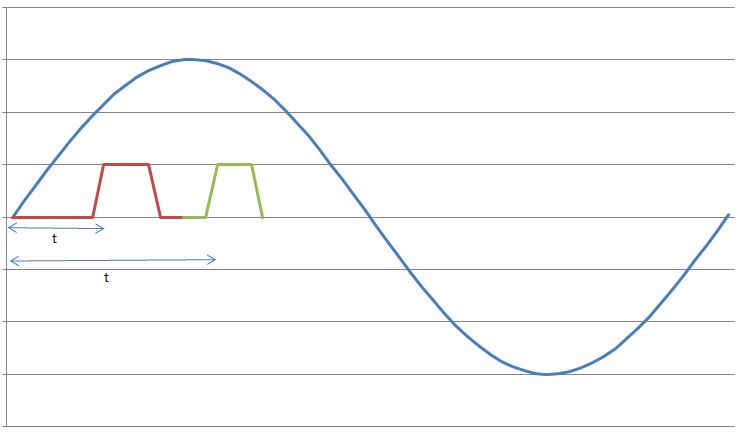
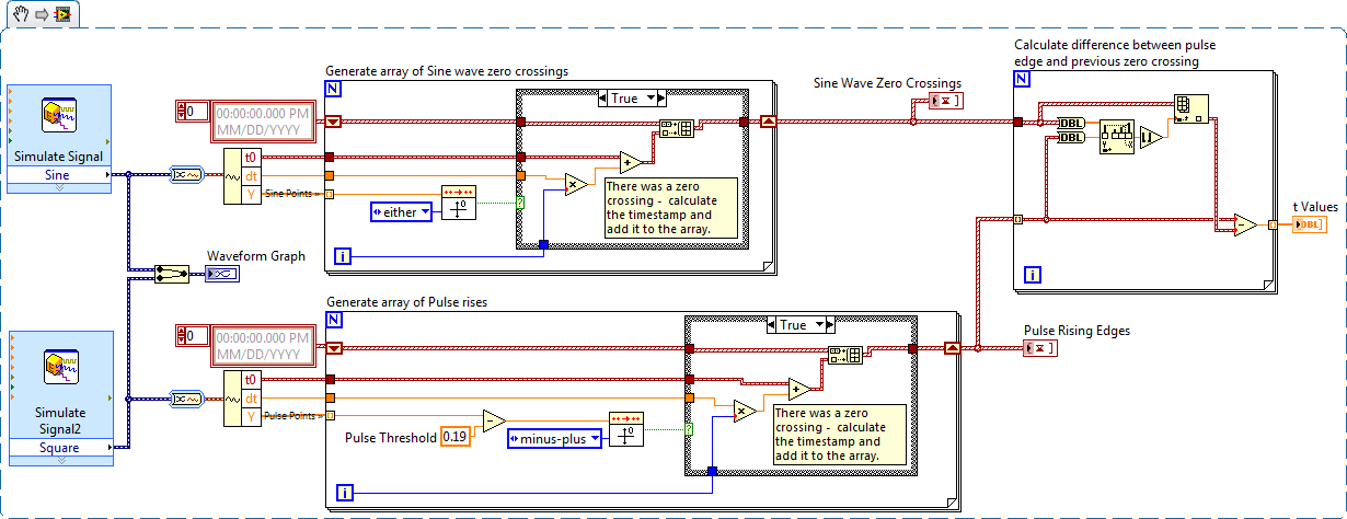
I have a sine wave of 50 Hz and a pulse of the signal on the same chart. The difference in phase between the two is between 0-90 degrees.
Now I need to calculate the time difference between (when the sinusoidal wave passes through zero volts) and (when the pulse increases). The frequency will remain about even for the two signals.
The request is for a three-phase generator. In simple terms, when the difference in time between the passage to zero of the sine wave and pulse increases increases, it means that the load on the generator has increased.
I am a novice user of LabView (version 9, 2009), maybe it's a very simple problem but I was pulling on my hair for the past few days and couldn't understand anything. Any help would be greatly appreciated. I use DAQ USB-6008 to measure these tensions and the impulse of the generator and a sensor
I have attached a jpg file (a graphic that I just did with excel to explain). The time 't' is what I'm trying to measure
See you soon
Zdzislaw
Awais.h,
For problems of this kind I recommend start writing the granular steps you would take to manually fix this problem. You can't say LabVIEW (or any programming language) If you can't succinctly describe the solution to your problem.
The I want to address this problem is to:
- find all the zero crossing points and edges on the rise
- for every rising edge find the difference between the timestamp and previous passage by zero
Here is an implementation of this algorithm LabVIEW:
-
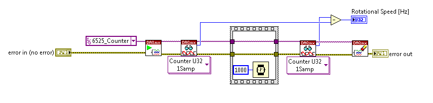
With the help of the meter from 6525 to measure the frequency: is there a more orderly way?
I am currently using the high speed on a module USB 6525 meter to measure the frequency of an object in rotation via a sensor hall-effect.
I was wondering if there was a simpler way / more effective this encoding than that?
Everything that I currently perform the current meter reading, wait a second, take another reading, and subtract one from the other. The result is the frequency in hertz.
Is there a way to get the 6525 to return the number / change County after 1 second?
Thank you
On the 6525, you have a country of the event and you can't make a measure of frequency.
-
Measurement of frequency with the NI 9402
Has anyone successfully was able to measure the frequency in SignalExpress with the NI 9402 module? I have the 9402 connected to a tachometer (on a centrifuge) which puts a TTL signal. For now, I can get the light input line to work. (Right click on the project, acquire signals: DAQmx Acquire: digital input: input line.) When the tachometer completes the first round, light or the 'blip' lights indicating the sensor then goes back to the shore for the rest of the round. I would like to read the frequency of this "blip" instead. I can't understand the required parameters in Signal Express. I tried (right-click project, acquire signals: DAQmx Acquire: entry of meter: frequency) but maybe I do not have the correct settings. This centrifuge works usually between 0 and 3 hz. I have attached a picture of what I have. I am doing this correctly, with incorrect parameters? Or is there a better way to do this? I need to read Hertz over time. Thank you!
Hi Choover,
Even if you use the 0 meter to measure frequency, your singal acts at the door of the on-board clock source to measure the length (and thus frequency). This is why you must use PF1 to connect to the door of the meter. You can learn more about how DAQmx takes measurements of meter in any manual of cDAQ chassis: http://digital.ni.com/manuals.nsf/websearch/2C061605E17C7D04862578D200677B90
Brian
-
VI to convert input signals NI 9402 in a RPM value, based on the frequency of the pulses
Hello
I'm looking for a VI convert an input signal NI 9402 in a RPM value, based on the frequency of the pulses. Is there such a thing that exists in the library of national instruments?
I run LAbview 2014 integrated control and monitoring on on a cRIO 9802 high performance integrated system with NEITHER 9402, 4 channels, 50 LV, LV TTL Module input/output digital, ultra high speed digital i/o for the cRIO module.
Any help would be greatly appreciated.
The easiest way is to use the FPGA to get the time between the edges of your pulse increase (shift registers to maintain the current situation and the time will be necessary). This will give you the period. If it's a single pulse per turn, then the number of laps is just 60/T, where T is the time in seconds.
Maybe you are looking for
-
Satellite P300 (PSPCCE) - Cannot install audio driver XP
Hey all,. I spent from Vista to XP Pro SP2. I installed almost every key factor, noise caused trouble. I have no audio hardware listed in Device Manager. Only: 2 times a PCI device, SM Bus controller and an unknown device.And because of that will not
-
SMU-1065 maps won't initialize restart
Hello I have a few cards as 6535 and 6561 SMU-1065... All the drivers are installed and I see them in the Software NI MAX. I have this problem, if I opened my computer and the victory has been downloaded, then I turn on my pxi... But the cards are no
-
To change the XP pro key, the registry is not change...
Hello Im trying to change the key of my XP pro PC in the most well-known way (through the registry), but the register does not accept the changes. I change content restarts, wpaeevents pc and it keeps the old values. I did it with the PC in the field
-
Play a record of a Question NAS200
IM thinking of moving from a NAS200 to one of the newer models with Gigabit. Can I move drives of NAS200 for newer models without having to reformat? Jorge
-
I need to install the device basic system for my acer aspire 6920
I need to install the device basic system for my acer aspire 6920