Measure the resistance with PXI DMM 4072 on different frequencies
Hi all
I tried to get on board various and unable to find solutions for that. I'm trying to measure resistance using NI PXI-4072 on frequencey 1 kHz, but not luck. When I try to use Agilent LCR meter I see the correct value of the resistance.
I've seen a few posts on this but don't have no satisfactory solutions.
In above post, someone said that I can use 4072 DMM OR digitizer, does not have a lot.
Can someone please provide the right path for me to solve this problem.
Thank you
Hello Puneet_K,
I checked the data sheet and the method of measurement described in the specifications of the NI 4070/4072 http://www.ni.com/pdf/manuals/371304g.pdf; indicates that the ability is measured using an alternating signal and select the test frequency range, for example 3 kHz, 1kH or 91 Hz. The resistance is simply measured using a DC signal, and it is often sufficient to measure the internal resistance of a battery. If you need a more flexible control for the measurement, you probably get a card like the function generator and then set a multimeter to measure the voltage and another DMM to measure the current and calculate the impedance of these values.
I hope this helps!
Kind regards
-Natalia
Tags: NI Hardware
Similar Questions
-
How can I use 2530 b and 4065 to measure the resistance between two selected pins?
I want to be able to select 2 corners on a test with 2530 b set-up and measure the resistance between them with a 4065 DMM (PXI all). Ankles in question are each in blocks of 32 different poles, so I can match them in a double configuration 32 x 1 four or 64 x 1 if necessary. I can measure the resistance between several different pine sets as 0 on 33 pine pine, pin 0 at pin 34 pin 0 to 35 pin and pin 1 to 34 pin, pin 1 pin 36, etc.
I understand how to measure resistance between a given pin and Earth using the the 2530 4065/b using the wizard OR-DMM/Switch Express, but it is unclear if I can measure the resistance between the two pins of selected by different user. I am a newbie of labview, used to write things in c#, so it may be something very trivial (I hope).
Any ideas?
Thank you
-Russ
Hey Russ,.
I recommend starting with the following example (located in the Finder the example ('Help' to find examples):)
"" Material input and output"Modular Instruments ' OR-Switch" niSwitch Dmm Switch Handshaking.viBecause you use a scan list, you can simply drag the two connections to the same entry and then the switch will wait for the two to settle before you send a trigger of the DMM... problem solved. For example, to connect the CH1 to Com0 (DMM +) and CH93 to Com4 (DMM), then take a measure, then connect CH38 and CH120 to the DMM, you would use the entry list of scan to the following address:
CH1-> com0 & ch93-> com4; CH38-> com0 & ch120-> com4;
Note You can have as an entry in list of switch module scan. In addition, you can only have a single advanced analysis and a measure full per switch module.
-
Measurement of resistivity with MyDAQ on TEC ca
Hello
I would like to ask for advice: we would like to measure resisitivity Peltier-elements. If we use the DC method, due to the cell voltage-Seebeck effect, we don't get the value of the true resistivity. The common method to use the measure of ca in the case of these devices. I would like to know if it is possible to use a device of MyDAQ for this task? As a first approach do us not need more precision, it would be more as a test of 'broken-element' (there is usually a significant change in the nominal AC resistivity value indicated by the manufacturer).
What would be the best way to make a simple measurement? What if I use an analog output of the MyDAQ lets say at 1 kHz, and I drive the Peltier element with this AC voltage source? I connect a resistance in the series, and I measure the AC voltage on that drop. After the results, I could calculate the current and the resistance of the AC of the Peltier element? Of course, I choose a resistance so the MyDAQ can drive the network.
What is your opinion, where to start?
Thank you!
Sounds like a good chance to learn more about these devices. In these conditions, I would do the same thing: try with what you have.
A quick glance at the plug MyDAQ it is clear that the current of the AO is limited to 2 my. I probably set the zone of OCCUPATION for about 2 V and use 1000 ohms in series with the Peltier device. That will keep the current in the 2 limit my. Two lines of AI to measure the tension on fixed resistance and the Peltier device. Then, you can calculate the unknown resistance.
If you were doing a production test or did the measure with a DC bias, I advise to use a transformer to couple the AC component in the CC line. This becomes a little more complicated to implement, but has much to versatility.
Please post after you have tried and let me know what you found.
Lynn
-
Measure the pressure with NI9205 in Mode CSR
I use the NI9205 module to measure the pressure, but when I connect two transducers of pressure for the module in the CSR mode there is a decrease of output signal of the pressure sensor and when I dissconnect it the signal to return to the previous value, also when I use the differential mode after a few seconds the output signal turns into a 50 Hz oscillation , can you help me please?
the pressure transducers are PDCR 4011, output 200mV and must provide of 10V and I use two similar power supply for transducers.
Thank you
Omid
Hello Omid,
It doesn't sound like the shields were inducing 50 Hz noise that you saw. They might have been picking up some other equipment in the room, and I think that Earth shield is the right solution for the problem.
Best regards
Adam G
-
Specifying the location of the cluster with several folders (same name, different hierarchy)
I am able to create a cluster and place it in a folder. However, I don't know how to set it for a specific folder when there are several folders with the same name across different hierarchical depths.
For example, suppose I want to create a cluster in the Department of human resources:
New-Cluster -Name Cluster1 -Location (Get-Folder HR)
Then assume that a HR folder is created on several issues, such as the following:
Datacenter-Corp.-HR
Data Center-NY-HR
Data Center-CA-HR
...I could then create the cluster in the Department of human resources of NY:
New-Cluster -Name Cluster1 -Location (Get-Folder NY | Get-Folder HR)
But what can I do if this depth is not standardized or changes, such as the following:
Datacenter-Corp.-HR
Data Center-East Coast-NY-HR
Data Center-West Coast-CA-HR
...Is it possible to see this full path, regardless of the depth of existing clusters?
How can I create a new cluster in a file which can be of various depths and have the same name?
Thanks for any help.
You can go down the road with the following script.
At the end the variable $fld contains the final location of the path and you can make a New-Cluster - location $fld
$folderPath = "Datacenter\West Coast\CA\HR"$fld = $null$folderPath.Split('\') | %{ if($fld){ $fld = Get-Inventory -Name $_ -Location $fld -NoRecursion } else{ $fld = Get-Inventory -Name $_ -NoRecursion }} $fld -
Basic measures and the output impedance of the change with PXI-4461?
Hello
I am required to build an audio station with platform PXI OR test.
It is my first experience with Renault. So I don't really know a lot...
The PXI-4461 is a replacement of a former HP audio Analyzer. The measure is quite simple:
1 generate fixed freq signal and measure AC RMS power
2 measure THD (total distortion harmic) at frequency fixed
3 measure SNR (signal to noise) at frequency fixed
4 generate and measure DC signals
5. change the output impedance of 50 ohms and 600 ohms.
If I have a good feeling on which tasks 1 to 4 are feasible. I would like to ask if the task 5 (change the output impedance) problem possible?
If this isn't a work around?
As for tasks 1 to 4, it is possible with out doing 'a sound vibration' Toolkit?
How helpful the Toolbox will be for the tasks listed above (humble).
What should be my starting point learn to manage these measurement with Labview?
Thanks in advance
Hi Hazkel,
Sound and Vibration toolkit will help a lot with steps 1 through 3. This without the Toolbox would require a very high level of knowledge with LabVIEW and you will probably run again for complications. In response to the fifth step, I tried to adapt the output impedance and am not able to do so programmtically. However, you can still do this in hardware by adding a shunt resistor and potentially switch between if necessary impedances. We have an article that deals with impedance matching and a circuit configuration to set the impedance if you are interested:
Impedance and impedance matching
http://www.NI.com/white-paper/3475/en/
I recommend starting with examples that we have already built in LabVIEW to familiarize yourself with the concepts. You will find them by clicking on help-> find examples-> search, then search for your application. Please let me know if you have any other questions.
Thank you
-
Help, please! Experiment to measure the resistance of the contacts in the relay contacts
Hello
I am completely new to Labview and have been asked to try to use the software and hardware to develop a VI to measure how the relay contacts contact resistance deteriorates with thousands of cycles. I have succeeded in one NOR cDAQ-9172 containing NI 9219 and NI9472 modules interface and can access them through the DAQ Assistant.
What I want to know is, how do I activate the relay I test and turn off using a pulse and keeping a count of operations and at the same time a measurement (this can be in each cycle of 100 or 1000) and save it in an ASCII data file?
All I have at the moment is the documentation of OR and a book titled Labview for engineers and scientists by John Essick, who I work slowly through.
It's such a difficult task VI?
Best regards
Andy
You can have a digital task as an analog input task running on the same chassis. You just turn the digital output of the cycle the relay and read with your analog inputs.
DIO most did not have enough current to drive a relay, then you want to get a digital stamp which can provide enough power for your relay.
Oh and check out the free online training modules
Introduction of 3 hours
Introduction of 6 hours
Bases LabVEW
Paced self-study for students
Self Paced Training beginner to advanced, required SSP
LabVIEW training Wiki
OR learning
Getting started with products OR -
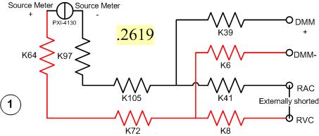
I have a problem with a PXI-2530 switch card work in matrix mode 4 X 32. I need to determine the resistance of the pairs of specific relay within the matrix. I have a PXI-4130 and a PXI-4071 in the same chassis, so I take measures 4-wire in a configuration like this...
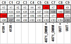
Resistance symbols represent relays in the switch. Here is a representation of matrix-style switch routes I use. (This should look more like the interface of soft face before switch)
The two diagrams represent so how I take my measure. I shorted outwardly columns C8 & C9 (shown in the first graph), I am sourcing 500 microamps of current and toggling the current source for a positive and a negative measure, I am able the voltage with the DMM. For the above measure I'm mesure.2619 ohms. This should be of course my resistance of the relay K8, K41, as well as Terminal block and wiring.
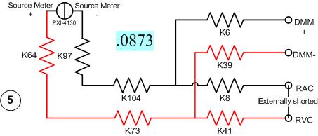
Here's another schema. This should measure the resistance of two same...
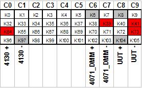
All I have changed is routing between the meter from the source. Here's the view from the matrix...
With this measure I'm mesure.0873 ohms. I can have the same resistance as the first example except getting a very different measure.
It gets even more interesting. If I had to take 4 pairs of wires, I use here, there are 16 possible configurations. I took each of these measures, and half of them gave me environ.25 ohms while the other half gave me environ.09 ohms. I tried this on a 2nd chassis and got the same result. My data are in the attached sheet. (My examples above are rows 1 & 5.)
Taking the measure of how we are, all these measures should be substantially the same. I have a current source constant, (I even tried a crimp in instead of the 4130 and got the same result.) and the meter is high impedance. If I had a pattern for the PXI-2530, I could do a little more analysis to know why I get various measures. Is there some diodes clamp on the lines or columns in the matrix? Something external must act solange this circuit. If I can find out what that is, I could determine my resistance to relay to a quantifiable level of uncertainty.
Any help would be greatly appreciated.
Greg
It seems that I can't remove. The correct message was placed here...
Once again, my apologies for the incorrect positioning of the post.
-
measure resistance with USB-6009
I am measuring the resistance of a photocell using the USB-6009 case. There is an option of "resistance" in the DAQ assistant, but it does not display the values on the right. Here's what I do:
Connections: GND - photocell - ai0
I'm really not sure if this is right, but I assumed that he could measure the resistance as a multimeter. I have not tried doing a divisor of tension and using the Ohm's law.
DAQ Assistant settings: I 'add channel' by using the more blue and choose "resistance". Then, I chose ai0 under USB-6009. I set the max and min values and read it all the time. First problem, playback is generally negative and it flickers a lot. I read about - 1.3 k when I do that with a k resistor 10 regular (not a photoresistor)
Obviously there is something wrong, but I'm very new to all this and cannot figure it out by myself. Any help would be much appreciated.
Thank you!
The 6009 cannot measure the resistance as a multimeter unless you can prove that a current as the wizard by default source is set to. In itself, it can measure a voltage. Then, use a voltage divider.
-
measure the temprature of thermistor using 6225
Hello
I'm using LabVIEW 8.6/DAQmx with a DAQ card 6225 of series M, connected to a terminal block of CB_68LPR. I want to measure the temperature of a thermistor.
First of all, I connect the two wires of the thermistor to AI6 (J25) and HAVE GND (J24) because I assigned AI0 to Ai5 to six voltage signals.
When I tried the example of temperature measurement, if I set up the channel as "2-Wire thermistor Iex" ai6 and choose the internal excitation source, I got the error message "measurements: device to which is attached the sensor was not a source of excitation internal avaible. But the requirement for this example indicates that the PXI-6225 can run the example. So here are my questions: is not my connection reflectometers to the terminal block? Which device should provide the excitation source, the map DAQ or other Terminal, if I really want to choose internal source?
Then I tried to use DAQ Assistant to configure the channel as "Vex 2-Wire thermistor" ai6, I received the error message "measurements: configuration 2 son resistance is not compatible with the excitement of tension", no matter if I choose 'Internal' or external"source of excitement." But in general configuration 2 son is good for thermistor. So my thermistor is not the type thermistor Vex? So, what type of thermistor is Vex thermistor? The technical details of my probe says nothing if it is Vex or type Iex.
Thanks in advance,
Caizhen
Hello Caizhen
PCI-6225 doesnot have an internal excitation source, but you can use one of the AO as an excitation lines if you have not the external voltage source, in this case, you should always configure your task as external excitation and measures four sons and in the program, you can take care of task AO where you can specify what exciatation you need. The measure of two sons is not supported in Vex-thermistor task. The connection diagram is shown in Measurement & Automation Explorer (MAX) in your task DAQmx.
Another possibility is to you can measure the resistance of the thermistor and map it to the temperature at two scales, but you will still need to have the excitement of current external OR-6225 has not built in power source, which is what he does in the task of Iex-thermistor.
Keep us informed on updates.
Thank you
nAyer
-
measure temperature pt100 with cRIO9211
I can measure the temperature with a pt100 in cRIO9211? I wanted to measure of 0 ° c to 100 ° c...
Can someone please show me how?
Thank you very much
Best regards
Hello
Thanks for posting your question on the forum of National Instruments.
Unfortunately, you can't have a RTD (generally with a PT100 probe) measure on a module 9211.
9211 module is dedicated to the use of thermocouples.
I suggest that you use a 9217 or 9219 rather (more information here).
I hope this answer will help you.
Best regards
-
measure the State of the output to USB-6525
Hi, is it possible to check the status of microsatellites in a USB-6525 using a multimeter. I hooked up a meter to measure the resistance through the P0.0A and P0.0B output connections. I wanted to use the automatic test routines to check the SSRs were closing. As expected, there was an open circuit when LIFE expectancy was 0, but the circuit seemed not close when I changed the TTL of 1. Do I need to connect to a power source and load to be able to see the closing SSRs? Is not which is what a multimeter?
Thank you, Nick
Nick,
Multimeter will not provide the source of tension and support you need. Check out this link. http://digital.NI.com/public.nsf/allkb/B0FF01B2AFFA52FC862573A2005A9570
-
Any suggestion on how to monitor the errorlog with a Plugin?
Hey all,.
I want to monitor the error log of MYSQL with my Plugin database and want to make the metric display in the user interface to allow users to know what is the content of the error log. I have a big problem to do this. What I do now is line number each time after registration log scanning errors, and the script will use the number to know where the beginning for the next scanning process. The whole process works fine as long as no one click on the metric in "All the metrics" page, which will trigger the execution of my errorlog script followed to get data in real time. Then changed the line number and content between these two line number of error will not be transferred to the WHO. It seems that there is no way to ban users click on the metric. :(
Someone at - it ideas? or experiences?
Any help will be appreciated!
Thank you
SatineThe behavior that you saw in the database product seems to be a product of using a USER by scope property in the QueryDescriptor. USER scope indicates that the property value must be specified interactively by the user or by placing it in the collection file.
So, I saw not someone do this, then you have to play with these instructions to operate on right...
Step 1:
Put a property with USER scope in the QueryDescriptor of your metric system:
uprop I don't think that you can still use this property. It should be enough that it is configured.
Step 2:
In your preferred collection file, in your MetricColl put an ItemProperty to measure the user with some sort of default:
foo What it must do, is to allow normal to continue collections because they will use the value for a property of element in the collection by default file, but it will prevent the real-time collection of the metric given that this value will not be filled.
This property can appear on the page of the metrics and policy settings, so blandly call enough where users think to do anything with it...
-
PXI-6704, parallel to the measurement of the resistance
Hello
I'm in show two separate circuit analysis procedures. First of all I would like to provide two pins with current and measure the response of circuit elsewhere, and second, I want to test the total resistance not fueled between those two pins. If I have a current PXI-6704 output wired to the pair of pins and the value 0 output amp, it will interfere with the measure of resistance to these pins (as a parallel resistance) or if it excludes all signals and appear as an open circuit?
I can use the PXI switch to connect and disconnect the DMM to measure, but test specifications require no supply current through the switch.
I don't have the equipment to hand, I know it would be the fastest test. We design the test set-up circuit in parallel with the PXI test chassis.
Thank you
Mello
Hey Mello,
Thus, the output impedance of your card is 1GOhm, so unless what you measure is huge, so it should appear as an open circuit. I hope this helps!
-
How can I measure the variable tension with the DMM and switch?
Hello, engineer,
I am a student, I want to measure the varying tensions from V to Via. I have the following equipment: SMU-1065 PXI-4065 PXI-2529. I use the PXI-8360 and PXI-8361 to connect with my PC. I hope I can do that when I have the next blood I should click with the mouse and connect the right position to the object of measurement.
How can I achieve that?
Any suggestions with great satisfaction.
Since I know a little English, if I did not explain my question clearly, please ask me.
Best wishes.
Kind regards.
chuanyuehuoxian
Yes, you can.
You can set the samples when using DMM.
You can also refer to the example in LabVIEW.
THX!
Maybe you are looking for
-
my browser.newtab.url keeps returning to the time where I change it
I want to open my new tabs as my homepage to google, but when I change the browser.newtab.url on www.google.com , it comes back to what it was before every time I close firefox.Can someone help me?
-
Safari address bar showing several addresses at the same time
Anyone else having problems with the address bar. No work to present frequently visited sites and and after visiting the sites manually or via Favorites addresses are crushed between them (showing several addresses at the same time).
-
Using the modem from the power of a XAC1900 with an EA9200
Hi all Does anyone know if modem a XAC1900, especially the power brick, can be used with an EA9200? It looks to me that it may, assumping cylindrical connector is the same standard connector on the EA9200.
-
How to set up Windows Fax and Scan with Brother MFC-7440N printer/all-in-one
Hello, I'm trying to set up Windows Fax and scan using my all-in-one Brother MFC-7440N printer/fax/scanner. When I go into the Windows Fax and Scan menu, I'm going to Fax > tools > accounts Fax. Then I select 'Add '. When he asks, I then select "Conn
-
Installed Home Premium, but would like my old Windows Ultimate product key...
So, I got this laptop I use customized online, it's a clevo p150 I believe... and it came with Windows Ultimate... Failure of my hard drives last year and I had to start. I could not find my product key, so I used an old Vista CD I got from my last l