measure the tension between adjustable borders
Hello
For my program, which I use to read temperatures and flows, and etc., on an engine test bench, I want to be able to build in a sort of borders of adjustable threshold for the minimum and maximum values for the tensions. When the engine is not running, there are still some low floating values visible on the façade. I want to put in a few border/threshold voltage values. This value should leave the front panel displays to display zero when the signal is very weak and floating. Is there a function for this? For ceilings, it is not really local, but I wonder if there is a building block for this already present in labview.
My program should also be attached.
Thanks in advance, best regards, Theo
Is that what you want for your noise suppression? It uses the range and force? to test the signal against the limits and replaces everything off of the beach with zero data.
Lynn
Tags: NI Hardware
Similar Questions
-
How can I use 2530 b and 4065 to measure the resistance between two selected pins?
I want to be able to select 2 corners on a test with 2530 b set-up and measure the resistance between them with a 4065 DMM (PXI all). Ankles in question are each in blocks of 32 different poles, so I can match them in a double configuration 32 x 1 four or 64 x 1 if necessary. I can measure the resistance between several different pine sets as 0 on 33 pine pine, pin 0 at pin 34 pin 0 to 35 pin and pin 1 to 34 pin, pin 1 pin 36, etc.
I understand how to measure resistance between a given pin and Earth using the the 2530 4065/b using the wizard OR-DMM/Switch Express, but it is unclear if I can measure the resistance between the two pins of selected by different user. I am a newbie of labview, used to write things in c#, so it may be something very trivial (I hope).
Any ideas?
Thank you
-Russ
Hey Russ,.
I recommend starting with the following example (located in the Finder the example ('Help' to find examples):)
"" Material input and output"Modular Instruments ' OR-Switch" niSwitch Dmm Switch Handshaking.viBecause you use a scan list, you can simply drag the two connections to the same entry and then the switch will wait for the two to settle before you send a trigger of the DMM... problem solved. For example, to connect the CH1 to Com0 (DMM +) and CH93 to Com4 (DMM), then take a measure, then connect CH38 and CH120 to the DMM, you would use the entry list of scan to the following address:
CH1-> com0 & ch93-> com4; CH38-> com0 & ch120-> com4;
Note You can have as an entry in list of switch module scan. In addition, you can only have a single advanced analysis and a measure full per switch module.
-
measure the distance between 2 impulses (PCI-6221)
Hello
I have a digital signal that sends a pair of impulses (100ns width each) roughly every 100ms and I measure the time between two pulses of a pair (with a resolution of 100 ns).
For the moment, I got a card PCI-6221 to accomplish this task. Unfortunately, I have no solution until now only measures of counter, I found measure time between constant frequency signals, i.e. they cannot measure the distance between 2 single pulses.Any help / ideas / or even telling me that it is impossible to solve this task are appreciated
Are the two pulses on the same line?
If so, you need to just configure a task of the measurement period. If they are on separate lines, you would use a task of "separation of two-edge.
You might be to throw off by the timing of it:
If you do not configure implicit synchronization in your task, will start on the first edge after DAQmx Read is called. Thus, in order to intercept the signal, that you must configure your task, call DAQmx Read and then start your two squares.
If you want the task to control the signal continuously, you must configure name timing. In this case, you will receive a sample on each rising edge of the external signal (assuming that the two impulses on the same line) - If you start the task of counter before starting the production of pulses (which you probably should), then the same samples correspond to the time between pulses, the odd samples would be the time between each series of pulses.
More information on modes of counting on the 6221 lie in the M series user manual.
Best regards
-
I use the driver for Tektronix TDS3000 Labview to configure an TDS3034B oscilloscope and I try to measure the gap between the falling edge of a pulse on channel 1 and the edge failling from an impulse on channel 2. It seems that the TDS3034 can measure this in in-house by the use of the measurement on the front panel key, but how do I retreave using your labview driver?
Hi Tori
I am now in place and running, I already had the TDS3034B to measure the delay between the pulse on channel 1 and the pulse on two channels, as well as the pulse width tuned to channel 2. This was done by saving the settings on the scope on a diskette and cutting and sticking them in a modified version of the TDS3000 auto setup vi. I created from a simple VI which allowed me to manually enter orders for tektronix and found that the command "measure: meas1: data? went around.
Thanks for all your support on this issue.
-
Measure the time between the ridges of the periodic input signal
We have built a circuit which is supposed to mimic an Exercycle. We have an IR switch and a spinning wheel, the rccb meets a comparator circuit and the output of the element of comparison, we have running in LabView. We successfully were able to measure the number of rotations of the wheel and the total distance travelled by the wheel, but are struggling to measure speed. We cannot find a way to measure the time between picks in real time, which we could then divide the wheel circumference and calculate the speed in real time. The VI I posted has a square wave simulated rather than the signal we receive on our circuit. Thanks in advance for the help.
Jon and David
I think you're overloading the things trying to get the time between two pulses. Instead, you can use the VI Express your measures and select frequency for her custom. Then, you can multiply the circumference of the wheel of the frequency to get the speed.
I hope this helps.
-Christina
-
How can I measure the time between each two successive increase edges, using digital input?
Hello
I have tried two measure the time in seconds between each two successive rising edges on a digital input.
So far I managed to detect the rising edge, increment a counter at each rising edge and take the time during which the increase is edge
all I need now is subtract edge currently rising from the previous era of edge rising to calculate (T), which can be 1/frequency and display in real time for the user.
but I do not know how to do this

Can someone help me please!
Woah!

Sorry Apok, but your code becomes much too complicated and salty. I don't think that all records to offset or Boolean conversion/operators are necessary at all.
If you want to measure the time between two keys so it's another (much less complicated) way. It simply records the time when press button in a registry change, then compares the two.
-
Measure the distance between 2 points of glare
Hello
Does anyone know how to measure the distance between 2 points (attached Image) glare. The image shows 10 sets of points of glare. I appreciate if you can guide me to process the image and produce the algorithm to detect the 10 sets of points of glare and measure the distance from each game.
Thank you
Farid
Check if this will do
-
How can I measure the time between the two edges of successive increase, using digital input...
Hello
I'm trying to measure the time in seconds between each two successive rising edges on a digital input.
So far I managed to detect the rising edge, increment a counter at each rising edge and take the time during which the increase is edge
all I need now is subtract edge currently rising from the previous era of edge rising to calculate (T), which can be 1/frequency and display in real time for the user.
but I do not know how to do this
Can someone help me please!
Note: while I am in a position varies between 200 ms - 2 seconds
-
Measure the time between two digital pulse
Hello
For a non-critical calendar application, I need to measure the time interval between consecutive TTL pulses, ranging from the order of 0.5 s for a few seconds, with a low accuracy of +/-10-50ms. The interval being measured varies between the rising edge of the first pulse and the front of the next and so on.
I have several input lines I need to deal with. Because it's a critical machination low cost, I don't want to use digital counters for each line, so I work with an acquisition of data USB6008 and have connected the input rows TTL on the digital inputs of the device. Avoiding will be sufficient.
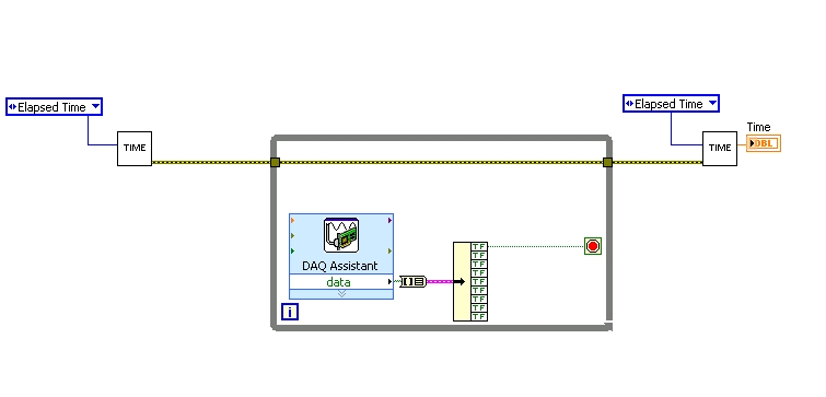
I found a good example of VI on discussion forums that does almost the same thing, only it uses instead of the DAQ Assistant user input. The VI works including the time the program going on in a while loop. I replaced with the DAQ Assistant output (a channel) user input in the hope that it is still work.
When I run the program in "run once" mode, it seems to work perfectly. However, in "continuous run" it measures only a very small interval, probably just the time between two samples. I think it has something to do with the help of a while loop in combination with the DAQ Assistant. Anyone who has any suggestions how to solve this problem?
Thank you!
OK... first of all, you should never use the button "run continuously. I wish that NEITHER would be to eliminate it, but told me that it is sometimes useful for debugging. If you want your program to run over and over again, use a while loop with a stop"" button.
If I'm reading your code correctly, you make your initial moment, and then collect data from data acquisition. When one of the channels is "T", you stop your loop and the end time of capture. (By the way, why you convert your table to a cluster? Why not just index the appropriate channel in the table directly?)
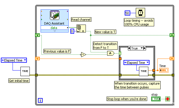
Since you want to capture the time between two consecutive pulses, you need to know when a transition has occurred... i. e when your digital line went from F (no pulse) to T (pulse start). This will give you your forehead. Right now, all you're doing is looking for a value T - so you have no way of knowing if you are looking for to the previous impulse again, or a new impetus. You also burn 100% of your processor with the way you have your programme in place.
You need a small loop delay so that your VI is not 100% of your hogs CPU time. Given that you can live with an accuracy of 50msec, what I suggest that you use.
See attached picture for you give an idea of how to implement. He will probably need some refining operations, but it should point you in the right direction.
I hope this helps.
-
How to measure the distance between the elements now? cmd + move tool does not work
I work on mac os x 10.9 and upgraded to photoshop cc2015.
I used to measure distances between items by pressing cmd + move selected tool.
Help please
Do you have any guides? View > show > Smart Guides
-
Hallo,
I use the following system:
- OR PXI-1044 with controller NI PXI-8109
- OR PXI-2564 switch module to turn on the monitor of my test device
- Data acquisition multifunction NI PXI-6259 to measure the signal that responded to the questionnaire jump
The two cards are the same - PXI trigger bus. For both, PXI-2564 and PXI-6259 I use DAQmx to set the reading and writing of the channels.
Now, I want to measure the time between the digital output, my unit turns and the analog input, which measures the response of my system.
I can't do work by myself, please help me!
I thank Ludwig.
Hi Ludwig,.
If you can't give us any VI we have difficulties with to help you.
Because I Donat knowledge how your program is mounted it is not easy to know where you should enter signals.
Here's a question similar to yours:
http://forums.NI.com/T5/LabVIEW/best-way-to-measure-time/TD-p/178704
and 2 external links:
http://www.ehow.com/how_8698983_measure-time-LabVIEW.html
http://objectmix.com/LabVIEW/385152-how-can-i-use-LabVIEW-measure-time-between-analog-pulses.html
-
best way to measure the thermistor
Hello!
We are looking for a solution for measuring temperature thermistor. I've read the material resources OR recommend for the thermistor measures.
Can you give me some ideas other alternatives for usable material temperature through resistance (we would use the default configuration, excitation of 2.5 Volts and a resistance of 5 + thermistor). So we need something capable of giving 2, 5V output and to measure the tension caused falling across the thermistor.Would be a NI USB-6009 suitable for this task? I guess that the resolution is not enough maybe?
Another option might be cheaper with a USB-GPIB interface Keithley 2010 multimeter, but in this case what should we use as a reference of tension?Thanks for the tips!
I want to second opinion to Henrik about repeatability in high resolution. Measures of temperature with Thermistors are particularly difficult. You have to worry:
- Auto-echauffants because of the power generated by the excitation current
- Time to balance the thermistor and electronic
- Stability of the excitation source
- Stability of the measuring device
In general, if you want something more than about 1% reproducibility, things start to me interesting. Of course, it's what makes it fun to do.
If you go the road of the sound card, remember that while most modern computers have quite high resolution a/d (sometimes up to 24 bits at 96 kHz) converters, you must watch the noise figures to get what you can actually solve. Off-board solutions (e.g., M - Audio Delta 44) will give you the best numbers of noise, since the ADCs are isolated from noisy inside your computer.
Good luck and have fun.
-
How can I measure the Max delay
Hi guys,.
I'm trying to add the module to the pulse to my VI. To do this, I guess I need to measure delay Max.
In my class VI, I have some instruments of the current driver, LED, spectrometer, camera and temperature controller. In addition, current is the variable I can change all the time during the execution of the VI.
I was wondering how can I measure the delay between the one and the other, and when I change the value of the current, how long will take to capture the right data
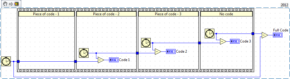
I knew that the number of cycles to measure VI all the time but how can I do for several parts
Thank you
Time required for the execution of some code can be done using 'Tick counts' now if you do not want it for full code but you want for specific elements of the code, then you must use the same function (i.e. "Tick count" separately for each section of the code.
-
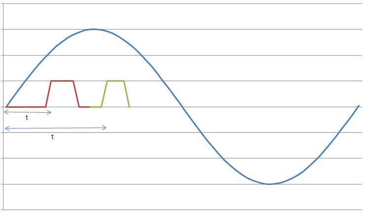
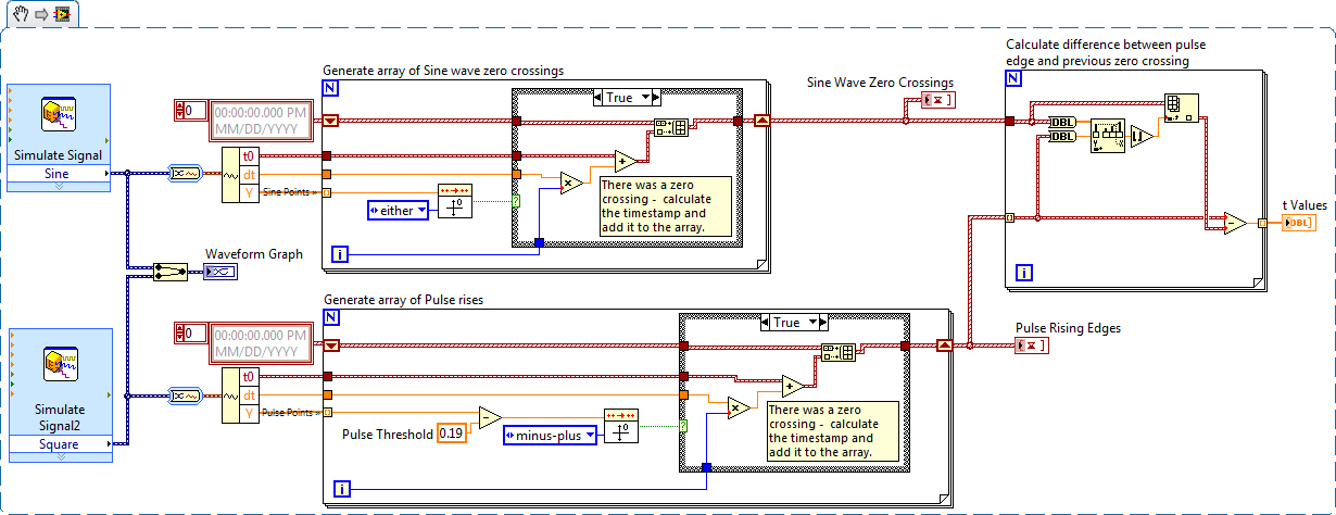
I have a sine wave of 50 Hz and a pulse of the signal on the same chart. The difference in phase between the two is between 0-90 degrees.
Now I need to calculate the time difference between (when the sinusoidal wave passes through zero volts) and (when the pulse increases). The frequency will remain about even for the two signals.
The request is for a three-phase generator. In simple terms, when the difference in time between the passage to zero of the sine wave and pulse increases increases, it means that the load on the generator has increased.
I am a novice user of LabView (version 9, 2009), maybe it's a very simple problem but I was pulling on my hair for the past few days and couldn't understand anything. Any help would be greatly appreciated. I use DAQ USB-6008 to measure these tensions and the impulse of the generator and a sensor
I have attached a jpg file (a graphic that I just did with excel to explain). The time 't' is what I'm trying to measure
See you soon
Zdzislaw
Awais.h,
For problems of this kind I recommend start writing the granular steps you would take to manually fix this problem. You can't say LabVIEW (or any programming language) If you can't succinctly describe the solution to your problem.
The I want to address this problem is to:
- find all the zero crossing points and edges on the rise
- for every rising edge find the difference between the timestamp and previous passage by zero
Here is an implementation of this algorithm LabVIEW:
-
How can I measure the variable tension with the DMM and switch?
Hello, engineer,
I am a student, I want to measure the varying tensions from V to Via. I have the following equipment: SMU-1065 PXI-4065 PXI-2529. I use the PXI-8360 and PXI-8361 to connect with my PC. I hope I can do that when I have the next blood I should click with the mouse and connect the right position to the object of measurement.
How can I achieve that?
Any suggestions with great satisfaction.
Since I know a little English, if I did not explain my question clearly, please ask me.
Best wishes.
Kind regards.
chuanyuehuoxian
Yes, you can.
You can set the samples when using DMM.
You can also refer to the example in LabVIEW.
THX!
Maybe you are looking for
-
How can I get rid of a new update of Firefox
When I turned on Firefox, this morning it automatically updated to version 29. I don't like. How can I go back to the old version and stop the automatic updates? Thank you.
-
After every night, the last updated 23/05/2013, pandora now not Exchange stations correctly If I listen to a station, swap to the other, the two stations are going to play at the same time, pause for a station and then swap to another still has the s
-
I'm running FireFox v19.0.2 and I continue to have the text on the pages raise you a messed up as if clear-type was suddenly turned OFF... tab and return in and its fixed... but he comes back and often. This only happens in FireFox. I'm running Win7
-
upgrade windows 7 to windows 8
Hi all I bought a lenovo X 1 carbon 3460 understanding that I would be able to choose windows 7 or windows 8. I am a user of windows 8 long and prefer to use the more recent operating system. Unfortunately, when I got my laptop home and it start it s
-
15r015dy HP: HP 15r015dy stop code
Teenager I forgot the password and now I receive, enter the password administrator or power on password. After three here I get disabled system [93650944] Is there an access code to go beyond that?