measurement of analog frequency with PCI or USB
I want to measure the frequency of a square wave 0 - 5V from zero to about 4 kHz permanently. I have to record the waveform, only get the frequency. The material at my disposal include:
(1) PCI-MIO-16
(2) 6062E DAQCard
(3) USB-6218
If none of these devices can do this? This seems to be a very common task, why can't I find the perfect example to do so. I'm not having any luck with the DAQ assistant. Can someone tell me a simple example?
You can also read the following link:
And look at the examples in the zip here
http://sine.NI.com/DevZone/CDA/EPD/p/ID/5000
Tags: NI Software
Similar Questions
-
Measures voltage and temperature with 6221 and USB TC1
Hello
I make a program to make measurements of voltage with a card PCI 6221 37 pins Council and measures temperature with a USB-TC01. I use Labview 2009 SP1 and basically my program reads the data, it displays in a table and records in a file, all at a time which runs in a loop until I have to stop the program.
The program is closed. I wasn't too sure about timing with the 2 devices. The tc01 works at a fixed rate, so I put DAQmx read 1 Chan 1 Samp. On the 6221, I defined a sampling frequency and chose to not 'continuous samples', set DAQmx read 1Chan Nsamp and 'samples to read' the value "-1".» And it seems to work fine, but only if 'samples to read' - 1 seems too easy. I'm missing something. What determines the speed at which the loop runs?
Thank you
Try putting a wait function (ms) in the loop. Set the value of waiting for 100 to 1000 ms. If everything goes faster than that, then the wait will determine the rate of the loop.
Lynn
-
Measurement of high frequency with the NI 9411
Hello
I would like to measure the frequency of a TTL signal with the 9411 OR in a cDAQ-9178 chassis. 1.6 at 48 kHz frequency range.
With examples of Labview digital frequency meter, it is not picking up on the signal. Any advice?
Anna
Hello!
After talking to an applications engineer of NOR, I realized that the input signal must be less than 5 v. In particular, the bass is between 0 - 0.8V and the top is between 2 - 5V.
Once I have limited input to this range, the module of frequency meter picks up on the signal very well.
Thank you
Anna
-
Output TTL triggers analog input with PCI-6251
Hello, I'm new to LabVIEW and have a question that I hope I can get a response on this forum. I am currently using a PCI-6251 DAQ card with a block of connection BNC-2120. I would like raise an event on an input, for example a sine wave, which is connected to AI0 analog. Then I would send a TTL pulse train via the digital output. What I'm describing can be better understood by the images of this link:
http://zone.NI.com/DevZone/CDA/tut/p/ID/3017
In the tutorial page linked above, they do mention the card PCI-6251, but when I read the specs and compared, 6251 also has analog and digital Board, trigger functions, as well as digital I / Os... so I think he should be able to do what I want it to do. Can anyone confirm this? If anyone could help me by providing a VI that could do what I ask, just to help me get started, would be greatly appreciated. Thank you!
Hello!
Please post on the Forums OR! My suggestion would be to use build it digital Pulse - Retriggerable.vi found in the Finder for example of OR. Open LabVIEW, go to help > find examples > input/output equipment > DAmx > generating digital pulses > generate digital Pulse-redeclenchables. Change the type of trigger for this departure vi > Analog edge and make the source one line APFI (pin 20 of your card is APFI0). This will generate a pulse based on an edge similar to a level that you specify.
I hope this helps!
-
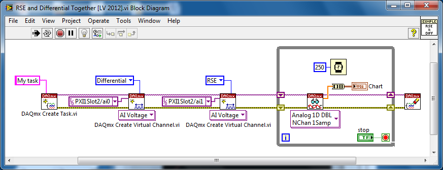
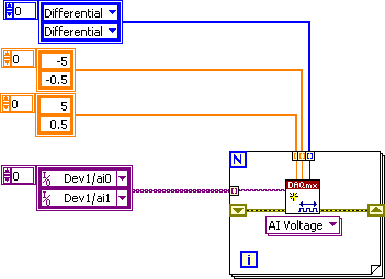
Several analog inputs with different configuration differential/CSR
Hello
Can anyone tell how to measure two analog inputs with different configurations using a USB-6009?
I am aware of the syntax for create virtual channels for the channels DAQmx create virtual so I created two strings using Dev3 / ai0:1 but I would like the first string of the CSR and the second to be differential.
So far I have found no way to specify the configuration of the separate channels.Any ideas much appreciated!
Jack
JackT wrote:
I prefer to use the 'low' level vi is therefore always curious to know if there is a way to set the configuration using the their.
It should be like this:
-
Problem with a precision of analog input on PCI-6111
Hello
I'm reading an analogue signal which varies from 0-11 V using a card of acquisition data PCI-6111. The signal comes from a Tube set (PMT) which is part of a microscope configuration, so it is very important that the resolution of the analog input signal be as wide as possible generate quality images. According to the data sheet for the PCI-6111, the analog input resolution is 12 bits, which should correspond to a sensitivity of ~2.686 mV for my voltage range.
To test this, I set up a task to analog input with a 0-11 V voltage range to read samples of an analog output, which I wrote a simple waveform. Since the 16-bit analog output resolution that I assumed that it would not limit the accuracy of this measurement. I have attached the VI I used for this measurement below. The analog input data are saved not truncated in a text file.
Analyzing these data, I found that the real input sensitivity is ~9.766 mV, corresponding to levels of voltage exactly 1126,4 and ~ 10 bits.
Is there a reason why the resolution of analog input is much lower that it is indicated on the card? What are some of the ways I could improve the sensitivity of this measure?
Best,
Keith
Sorry, when you mentioned the specs, I thought you already had them. If this did not come with your Board of Directors?
-
How to measure high voltage (60-70 v) and current (75-80 a) using a DAQ PCI or USB DAQ
Hello
I work with a system that works on about 5kW. The output of the system voltage can go maximum up to 60-70 v and thus the corresponding current around 75-80 a. I have 10 these systems that I want to read one by one continuously for long periods.
I am designing the automated system best suited for this and looking for the best material that would be appropriate for this purpose. Looking for options, I found that an SCC - A10 attenuator may be used to get the tension down by a factor of 10. But I'm confused, if the high current will pose a problem and also how to measure this high current.
I need to measure the voltage and current at the same time. Please suggest what would be the most appropriate fitting for the same (preferably PCI or USB)
The hope of a quick response. Thanks and greetings
Reena Sharma
Facilitated learning
Reena says:
Hi all
There is good news that the idea of using a compact data acquisition has been accepted by the authorities of the society. I'll be very grateful, if you could suggest me with some hardware modules suitable for my application and how I can use them best.
Thank you very much
Reena
I was able to make a few suggestions, but do not have the time to understand your needs and the forums are not the best solution.
Your Local OR representitive actully gets paid to do this kind of thing. a google search suggests THAT LME is in Pasadena. Zack Collins would be the contact rep
-
With the NI USB-6009 analog input lag
Hello
I try to acquire analog signals with NI USB 6009 using LabVIEW. (The signal is 50 Hz of the functional generator).
However, the acquired singnal has dynamic splitters, which is NOT observed by my oscilloscope.
I have no idea why this phase shift occurs.
Any information is welcome. Thank you for reading.
An image file will not help. Post your real VI. If Firefox does not work, use explore or Chrome to fix your VI (s)!
You have here a Subvi, I don't see what's inside and how it is configured. In addition, this while loop is ridiculous: there is no button to stop him running. Never use the red button to abandon for a normal shutdown of a VI!
Why you have configured NChan NSample? Measure a unique signal, Yes? For example, use 1 channel only.
Edit: why do not you play first with an example given, delivered with LabVIEW?
Your LabVIEW, go to the Help menu--> find--> material and output examples--> DAQmx--> entry--> and open 'Input.VI - constant tension!
This VI allows to enjoy your analog signal.
-
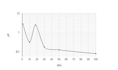
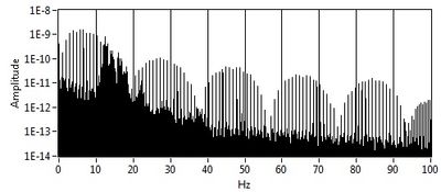
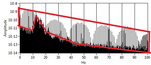
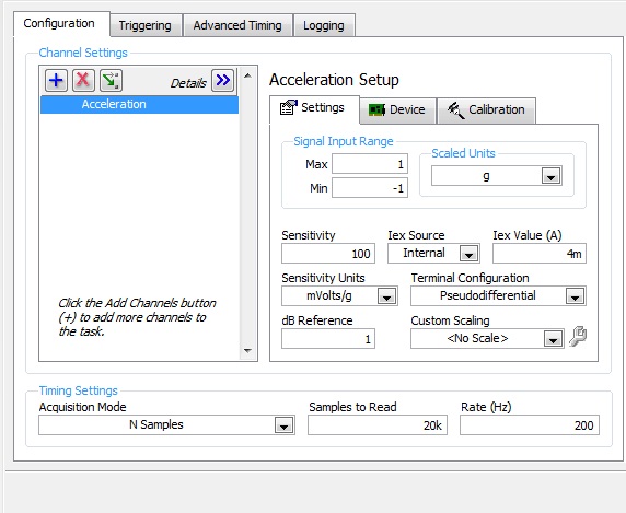
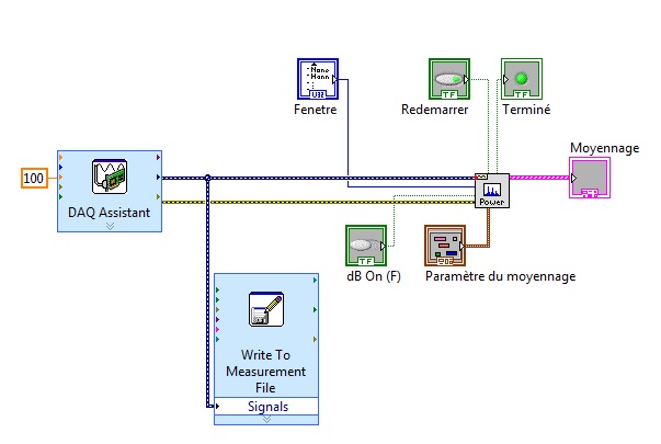
Noise measurement of an accelerometer with card PCI-4461
Hello world
I'm trying to measure the noise of an accelerometer, except with a card PCI-4461.
First of all, I measured manually this noise with the help of a HP35665 signal Analyzer. I get something like this:
And now with LabView and the PCI-4461 map, I get this:
My question is: Whence this part? And how to remove it? (Since there is no with the signal Analyzer)
I'm using LabView 8.5.
This is how I configured the DAQ acquisition:
and it's my VI:
Thank you in advance for help
Arthur
-
I use the outgoing/incoming analog DDK with the DAQ 6341 SMU map.
The examples, for example aoex5, show a single timer (method outTimerHelper::loadUI), but the example shows the DMA loaded with same size of vector data.
There is a comment in the outTimerHelper:
 call rogramUpdateCount, which implies that memory sizes different pad per channel can be used.
(the comment is: switching between the sizes of the various buffers is not used)
Nobody knows what should be the format the DMA buffer for data from multiple channels with different frequencies?
For example, we want a0 with a sinusoid at 1 kHz and a1 with a sine wave of 1.5 Khz. What looks like the DMA buffer?
With the same frequency for each channel, the data are interleaved, for example (ao0 #0, ao1 #0; ao0 ao1 #1, #1,...), but when the frequencies for each channel is different, what the stamp looks like?
Hello Kenstern,
Data are always intertwined since each card has only a single timing for each subsystem engine.
To AO, you must specify the number of samples that will be released to the AO. You also specify the number of channels. Because he didn't is that a single engine timing for AO, each AO will be channel will be updated at the same time to update clock tick. Data will be interlaced exactly as shown in the example because each channel AO needs output at each tick of the clock to update. The data itself can change depending on the frequency you want to copy.
kenstern wrote:
For example, we want a0 with a sinusoid at 1 kHz and a1 with a sine wave of 1.5 Khz. What looks like the DMA buffer?
With the same frequency for each channel, the data are interleaved, for example (ao0 #0, ao1 #0; ao0 ao1 #1, #1,...), but when the frequencies for each channel is different, what the stamp looks like?
In your example, you must come with an update rate that works for the two waveforms (sine waves of 1 and 1.5 KHz). To get a good representation of a sine wave, you need to update more than 10 x faster than your fastest frequency... I would recommend x 100 if possible.
Update frequency: 150 KHz
Channels: 2
Then create you stamps that include complete cycles of each wave you want to produce based on the frequency of update. These buffers must also be of the same size.
Buffer 1: Contains data for the sine wave of 1 KHz, 300 points 2 cycles of sine wave
Buffer 2: Contains data for the sine wave of 1.5 KHz, 300 points, 3 cycles of sine wave
You can Interleave them as before. When the data are performed through the ADC, they are out different sine waves, even if the AO channels are updated at the same speed.
-
problem of analog with PCI-6115 and BNC-2110
Hi, I have an acquisition of data PCI-6115 and BCN-2110 connector card I want to measure continuous analog voltage. Now I can permanently measure the intensity of light laser of photodiodes through channel 1 and get the reference through the 0. Then I can get the harmonic signals by the multichannel lock - DAQmx.vi. However, I also want to simultaneously detect another analog signal in channel of gold voltage 2. The problem is: Channel 2 voltage range is approximately 0.3 mV to 6 mV which is significantly lower than the other channel 2 (0 - 10V), how could put different prescription by channel continuously and simultaneously acquire all data?
I found that Dennis Knutson has provided the solution a year ago, which is listed below:
In the solution, it should be arrays of strings, lines, patterns, but I do not know how to apply it to my case. Is there a suggestion or another solution?
Thank you very much!
You have the autoindexed exit task and is not correct. Try the code below.

-
Measurement of temperature using Iex thermistor with PCI-6259
Hi all
I have I encounter some difficulties to measure the temperature using MAX with the installation of the thermistor Iex and would like to know if I missed something important. I use external current thermistor excited with 2 ladders and card PCI-6259 with MAX.
This is a channel that was originally set to measure voltage and MAX approx. 900mV since this channel, OK, the voltage converted temperature is about 30 ° C. Then I added a new channel and configured to measure the temperature directly with default installation MAX Iex thermistor. This is so the problem appears: I'll get a constant-273 C instead of 30 C as expected by operating the canal in MAX. I must have done something wrong here.
Your help is greatly appreciated!
Bryan
We discovered that the problem came from our wiring to thermistor does NOT of installation. If Differencial has been used, the conversion of MAX worked well. If this is not the case, only directly blood pressure will work. Bryan
-
How can I improve the rate of acquisition with daqmx and usb-6008?
Hello
I am trying to acquire data of analog voltage with a USB-6008. I'm under Labview 8.5 student on an HP laptop with a 1.33 Ghz cpu and 736MB RAM, apparently. I tried using the Daq assistant and the low-level Daqmx functions. My best results come with a task set in MAX for my analog input, and using the function 'Daqmx read' the 'unique double 1 d sample' value in a while loop. I insert the values returned in a table which built in the while loop, and then when I'm done, I check the number of samples in the table. In the test VI attached, I also use the time to Get before and after all loop. The best sampling rate I made using this method, is around 40samples/second. I have attached a VI below that illustrates this concept. In my actual application, the data acquisition code runs at a time while loop with 1ms, parallel to other code that controls the device I'm collecting data of. The sampling rate is roughly the same for my test below VI and my application program.
The 6008 datasheet gives the sampling frequency maximum 10 kHz. I'd be happy with 2 to 2.5 kHz, or as soon as possible; I'm sure that I can achieve a little more than 40 Hz. My first idea was tied to the hardware, but the 6008 cannot make acquisitions NI hardware.
My question is: How can I implement a faster sampling of analog voltages to a USB-6008 in LAbview? If I can't do it, is there another way I can taste the data more quickly?
Thank you
-SK-

To the best of my knowledge, the USB-6008 can do timed equipment acquisition. Don't forget that this is a multiplexed device, so if you add 8 channels so the maximum you can set is 10 k/8
If you are new to LabVIEW, I suggest that you try this sample program first
\examples\DAQmx\Analog In\Measure voltage. llb\Acq & Graph tension-Int Clk.vi Amit
-
reading of the analog inputs with RPC
Hello
Because LabVIEW can not handle this (in VI; the value that you have saved the excel file has not been the same, that I saw during the measurement...) This confused me for a long time
), I want to write a C++ program (IDE: Dev - C++) which can read & record 2 analog inputs of the NI USB-6009 box. For this, I looked for an example of National Instruments and I found a little. But my problem is that I can't even use any example, because it has always held a mistake, after that I have compiled and started.The error once the task has been created and has the :-200220 error number with the description "device identifier is invalid. But I do think that its invalid, because it's the xP example
I must say that I am new in programming C++, which means I could have a rookie mistake. And I couldn't find documentation or something for the NOR-DAQmx library.
Someone has similar problems with DAQmx and C++ and know how to fix? I don't really know what I can do now without a working example or documentations...
Hi Mario
It's the same thing. You didn't just save all of the data:
Please take a look at my comments in the attached VI.
Christian
-
Triggers the analogue output with PCI-4461
Hello
I'm trying to generate a signal of analog output triggered with a card PCI-4461. First I tried to use the feature OR DAQmx 'start analog edge' with the way analog input AI0 as the source and the channel analog output AO0 as task. After it gave an error that I tried to use the NI DAQmx 'start digital dashboard' function with PCI0 as source and channel of analog output AO0 as task. It ran, but did not produce any output. Now I wonder if I can use the trigger analog or digital of the PCI-4461 to all of the output.
Thanks for support you,
Pribislav
Pribislav salvation,
you still have this problem? I did exactly the same configuration (power play) and it works fine on my system. The PCI-4461 does not support analog triggering, that's why this error occurs.
Kind regards
Michaud

Maybe you are looking for
-
Primary control loop and loop DIO
Hello I use an X-series with Veristand 2011 card. I need to acquire some AI and DI whole. It seems that the AI will be supported by the main loop, which is very good for our goal for now. But what of the DI. Looks like the DIO loop works like a rate
-
How to change the number of items in number to Boolean, function VI table
Hi, I'm working on using the digital output of data acquisition to control the digital input of a DAC, and I used the Number function in Boolean table. VI to convert the number to a Boolean array. The maximum number is 4096, so it must be composed of
-
LabVIEW 2009 32 bit does not not on xp 64-bit
Hi all I tried to upgrade to LabVIEW 2009 LabVIEW 8.6 on the XP machine 64-bit windows. After about a deletion of 2 hours of installation 8.6 and later of LV 2009 it turns out that the device drivers are not compatible with a 64-bit computer. At the
-
Hi, like millions of others I get garbage/spam... never used to be a problem that the vast majority would be Royal to my mail in bulk in the hub. During the last weeks when they seem to go directly to my Inbox, so you can imagine how many times a day
-
Do not have precisely the difference ECCAS current date and the date, we pass to the function.
Hello I did a feature where when I go to any expiry date that I must check with the current date... and get the difference in days. When I change the value to this fuction 2012-01-05 and my current date is 2011-12-22 that I am getteing diffDays = 45,