Measurement of ca reference circuits
How can I measure safely referenced (neutral) DC voltage? The measured line a possibility of short circuit with AC live as well. I know that some sensors can provide insulation, but is there material OR who could do the same thing? 6218 OR seems possible, but there is a limit of 60V on Earth (which may not be suitable if the measurement line is shorted to Live).
Hi Lynn,
Thanks again.
Tags: NI Hardware
Similar Questions
-
PXI-6704, parallel to the measurement of the resistance
Hello
I'm in show two separate circuit analysis procedures. First of all I would like to provide two pins with current and measure the response of circuit elsewhere, and second, I want to test the total resistance not fueled between those two pins. If I have a current PXI-6704 output wired to the pair of pins and the value 0 output amp, it will interfere with the measure of resistance to these pins (as a parallel resistance) or if it excludes all signals and appear as an open circuit?
I can use the PXI switch to connect and disconnect the DMM to measure, but test specifications require no supply current through the switch.
I don't have the equipment to hand, I know it would be the fastest test. We design the test set-up circuit in parallel with the PXI test chassis.
Thank you
Mello
Hey Mello,
Thus, the output impedance of your card is 1GOhm, so unless what you measure is huge, so it should appear as an open circuit. I hope this helps!
-
Hello
I'm making an aplication with two main Vi. The first Vi is responsible for the configuration of different instruments. On the other hand, the second Vi is responsible for the different measures of an electronic circuit.
My problem is that I want to pause the first Vi when configurations were carried out then go to the second Vi and carry out measures. When the measurements were made, execution must return to the first Vi and continues from the point where the program has been suspended.
I am trying to solve this problem with the queues and some time a loop to stay the execution, but it does not work properly.
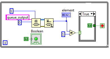
The following picture, I have attached the while loop. This loop communicates with the Vi second to check whether or not the measures are completed. But it is not working properly and I don't know why. My question is: this method is good to solve this problem or there is another method better than this? Or quite simply, the break of a Vi enforcement cannot be done.
Any help is appreciated.
Thank you.
Luisi says:
Thank you very much, your answers are very useful for me. I understand that the state machine is the best method to carry out the proposed work. But I have a problem, if I decided to do it in two different VI is for space issues. I think that I can't do that in one Vi. Is it possible to have two sides of a same Vi?
I will attach two pictures of front panels of the screws so that you can understand my problem.
In this first image, I have attached the face before of the Vi that supports the configuration of instruments. The table is the values of the configurations, and each line is an iteration. As you can see the number of lines can be configured (sorry is in Spanish in the picture), which means that the space can be bigger than that.
As you can see, I need two different screws to make this automazation. I've read tutorials on the state machine and I also looked at the model that is very useful and understandable. However, I don't see that this method can be used in a communication between two different screws. Certainly, I'm very confused and now I don't know that I have to do.
Sorry because the first question is how to pause the execution of a program (idle state) and now I'm adding these issues and the need for the two different voluntary initiatives.
Thank you for your attention! If you have an idea, I will be very happy that you help me.
There are several solutions for this. If you have a main executable (state machine), it may appear in the settings (your first picture) window and sends the settings as an output (or make adjustments to the main state machine and hide while the other is running). The main VI appears the window of measurement that uses the input parameters. Once the measurement is done, you save the file and return to the settings.
As a note, you will probably need a lot more than 3 VI, to get a good program structured and modular, I'm guessing 50, fortunately it's simple to do.

/Y
-
Want to use Lock-in detection with a linear detector with diode bars
Hi people,
I work with OR lock virtual amplifier to build a detection system that uses a linear led strips detector to measure the effect of an electric field on the spectrum of a molecule absorption. Traditionally, this technique was carried out using a single photodiode detector connected to an external amplifier of detent and the absorption spectrum was analyzed using a spectrometer. The lock would demodulate the signal of interest based on the wavelength. In my setup, I acquire any range (all wavelengths) simultaneously to speed up the experience and improve S:N. to do this, I use a spectrometer OOptics USB2000 + and NI virtual LIA. Each element of the photodiode array, then acts as a unique photodector calibrated to a specific wavelength. I want to demodulate the signal of interest of each element of the matrix of the photodiode.
After reviewing several of the messages on this forum, I start to worry if my setup actually work. So far, I have seen that everyone uses a detector single channel connected to a card scanner of some sort, which also acquires a reference signal. Phase delays would come mainly from electronics and cable lengths. In my setup, the detector is digitized by the 2 MHz ADC in the spectrometer OOptics and my digitizer OR is only to measure the experience reference signal. Because two ADC of separate instruments are used, this prevents the use of the vLIA? My intuition tells me that don't know, but I am relatively new to the use of detectors photodiode array for this purpose.
Any help would be greatly appreciated.
Timchem
Tim,
Now we are getting somewhere.
The effective sampling rate is about 70 Hz. Unfortunately, the time is probably metered software, which introduces additional jitter at the time of each data set. Sampling a signal to the Nyquist rate only gets you the minimum information on this signal and certainly produced very little significant phase information.
Given that the intensities of the pixels are measured at the same time, you have no worries for the phase shifts between the pixels.
Question about the synchronization: the spec introduces a measure whenever it receives a TTL pulse? Integration of 1 ms, then send 2048 data points, then wait for the next pulse? Assuming that's what he does, then you have a chance to lock a verrrrrry slooooow amplifier.
It would work something like this. Setting the sync generator to produce a measure trigger pulse every ms T, where T > 13 + 1 ms. Suppose that T = 20 ms (FLA = 50 Hz) to keep simple mathematics. Sets the modulating frequency to 1 Hz. Then you get 50 samples per period of modulation, or sample all 7.2 degrees.
Now I need more. You indicate that your alternative signal is microvolts. What is the significance of the component continues? The relationship between these two signals is the signal to noise ratio. A quick glance on Ocean Optics web site indicates that dynamic range for a single purchase is 1300: 1, which seems low for a device with a 16-bit A/D converter. This must be the limit of the photodiodes to an integration time specified. If the signal is really limited to this range, you can get into trouble. The lock-in amplifier depends on some signals actually being there, just smaller than the noise. In this case the limitations of photodiodes or the processes scanning spectrometer, it is possible that there are really no signal there to extract.
If your signal is a quantity equivalent to 10% of the dark current, you must get a signal you could accurately measure on average for about 100 cycles of the modulation frequency (1 Hz) to start. Your samples are stable for 2 minutes or more?
A different instrument may be the best bet.
Lynn
-
Connect 3 wire sensor in correct way NI 9209
Hello
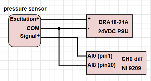
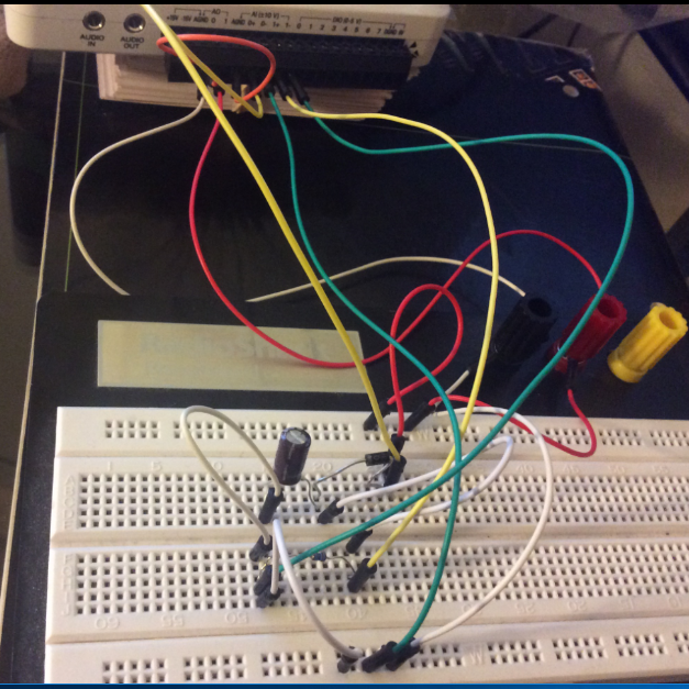
I have several sensors of absolute pressure with only three wires (a common thread, an excitement + and signal output +). I enclose the form in pdf format. I need to connect about 6 of these sensors to my NI9209 card inside a cDAQ chassis. I also have a power supply of 24 VDC. I would like to ask about the proper connection if I want to use the differential voltage measurement.
Can I just wire the elements in the following way (left photo), or do I have to follow the recommended wiring as described in the manual on page 14, the part 'floating differential connections' ( http://www.ni.com/pdf/manuals/376909c.pdf ), right? Thank you!
Edit:
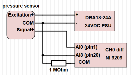
If I have to use the resistance of 1 MOhm, is it enough to use a single resistor connected between the pin of the NI of COM map and all the pressure sensors COM ports?
You need to have the input of COM on the module HAVE referenced in your municipality. However, if all your sensors are out of the ordinary even running, you need not the resistance of 1 M. The only reason why neither mentions that this connection is for incoming signals not referenced to the commune. Given that this sensor is only to give you a single output is completed, it would be much easier to just run the signal is broadcast to the module I and connect the COM to the power supply. Otherwise, you basically jump the COM signal toward the low side of each measure and the reference measurement to COM in any case.
-
I need a few persistent data store help of Pentecost
Hi, I have a problem, try to store persistent data, I m using Eclipse 3.4.2 and BlackBerry plugin, as I check my work with the correct laboratory and my code hasn´t issues only a warning I see on the laboratory code it s normal, but when I try to run the Simulator I get this:
"Eception exception: lack of measurement of the resource.
and this is the code
package com.rim.someguy;

//Import section
import net.rim.device.api.ui.*;
import net.rim.device.api.ui.component.*;
import net.rim.device.api.ui.container.*;
import net.rim.device.api.system.*;
import net.rim.device.api.util.*;
import net.rim.device.api.i18n.ResourceBundle;
import java.util.*;

public class measure extends UiApplication implements measureResource{

    //Variables for user interface fields
    private EditField numMeasureDev;
    private AutoTextEditField observation;
    private EditField lecture;
    private ObjectChoiceField choice;
    private EditField date;

    //Persistent data
    private static Vector data;
    private static PersistentObject store;

    //Resource bundle variable
    private static ResourceBundle _res;

    //MAIN

    public static void main(String[] args){
        measure app = new measure();
        app.enterEventDispatcher();
    }

    //Save Menu
    private MenuItem saveItem = new MenuItem(_res, SAVE, 110, 10){
        public void run(){
            StoreInfo nfo = new StoreInfo();
            nfo.setElement(StoreInfo.NUM, numMeasureDev.getText());
            nfo.setElement(StoreInfo.LEC, lecture.getText());
            nfo.setElement(StoreInfo.DAT, date.getText());
            nfo.setElement(StoreInfo.SEL, _res.getString(choice.getIndex()));
            nfo.setElement(StoreInfo.OB, observation.getText());
            data.addElement(nfo);

            //Storing data
            synchronized(store){
                store.setContents(data);
                store.commit();
            }
            Dialog.inform(_res.getString(APP_SUCCESS));
            numMeasureDev.setText(null);
            lecture.setText(null);
            date.setText(null);
            choice.setLabel(null);
            observation.setText(null);
        }
    };

    //Get Menu
    private MenuItem getItem = new MenuItem(_res, GET, 110, 10){

        protected int index;

        public void run(){
            synchronized(store){
                data = (Vector) store.getContents();
                LabelField label = new LabelField();
                label.setText("Selecciona el dato a mostrar: ");
                BasicEditField bef = new BasicEditField();
                index = Integer.parseInt(bef.getText());
                if (!data.isEmpty()){
                    StoreInfo nfo = (StoreInfo) data.elementAt(index);
                    numMeasureDev.setText(nfo.getElement(StoreInfo.NUM));
                    lecture.setText(nfo.getElement(StoreInfo.LEC));
                    date.setText(nfo.getElement(StoreInfo.DAT));
                    choice.getIndex();
                    observation.setText(nfo.getElement(StoreInfo.OB));
                }
            }
        }
    };

    //Persistent Object
    static{
        //Resource Bundle
        _res = ResourceBundle.getBundle("measure");

        //Get the reference to PersistentObject and set value to Vector if is empty
        store = PersistentStore.getPersistentObject(0xdec6a67096f833cL);
        //key is a hash
        synchronized(store){
            if (store.getContents() == null){
                store.setContents(new Vector());
                store.commit();
            }
        }
    }

    //Class created for a persistent object StoreInfo
    private final static class StoreInfo implements Persistable{

        //Data for elements
        private Vector elements;

        //Fields
        public static final int NUM = 0;
        public static final int LEC = 1;
        public static final int SEL = 2;
        public static final int OB = 3;
        public static final int DAT = 4;

        //in StoreInfo, add a new empty Vector with capacity of 4 elements and persist
        public StoreInfo(){
            elements = new Vector(5);
            for(int i = 0; i < elements.capacity(); ++i){
                elements.addElement(new String(""));
            }
        }

        //Retrieve Vector element
        public String getElement(int id){
            return (String) elements.elementAt(id);
        }

        //Set Vector Element
        public void setElement(int id, String value){
            elements.setElementAt(value, id);
        }
    }

    //Measure constructor declaration
    public measure(){

        //Create a main screen
        MainScreen mainS = new MainScreen();
        mainS.setTitle(_res.getString(APPLICATION_TITLE));
        numMeasureDev = new EditField(_res.getString(TEXT1),"",
                Integer.MAX_VALUE, EditField.FILTER_NUMERIC);
        lecture = new AutoTextEditField(_res.getString(TEXT5),"",
                Integer.MAX_VALUE, EditField.FILTER_NUMERIC);
        date = new EditField(_res.getString(TEXT6),"");
        choice = new ObjectChoiceField(_res.getString(TEXT2),_res.getStringArray(OPTION));
        observation = new AutoTextEditField(_res.getString(TEXT3),"");

        //Adding elements to Screen
        mainS.add(numMeasureDev);
        mainS.add(lecture);
        mainS.add(date);
        mainS.add(choice);
        mainS.add(observation);

        //Adding menuItems to menu
        mainS.addMenuItem(saveItem);
        mainS.addMenuItem(getItem);

        //Push all elements to screen
        pushScreen(mainS);
    }
}
If anyone knows what I m hurt you showme how please!
Two thoughts:
- If you have changed somehow the object type that you want to keep, you must remove the Simulator files before running again.
- How about you provide a clue as to where the class cast exception that happens? You are more likely to help in this way.

-
I get the error code 2 in the updating of the CC and what I read online, I need to use the uninstaller CC. When I try to do, he says "another version of the creative office cloud or another installation of Adobe is running. To continue please close the proceedings first. "And then he removes my office uninstaller. I disabled everything in Manager tasks. So there is nothing open.
It's very frustrating. I would just add that. I don't want you to uninstall PS and LR. I'm on the internet measured.
Reference:-https://forums.adobe.com/thread/1449867
-
Clause type and its Alternative to Oracle 10 g
Hello
I went through a few examples on the clause type in oracle 10g, but not very clear on this subject. can someone please explain it to me in detail and when to use it.
Also, how can we create the same performance as that of the model clause by using other means.[http://stanford.edu/dept/itss/docs/oracle/10g/server.101/b10736/sqlmodel.htm#i1006326]
Reference Models In addition to the multi-dimensional array on which rules operate, which is called the main model, one or more read-only multi-dimensional arrays, called reference models, can be created and referenced in the MODEL clause to act as look-up tables. Like the main model, a reference model is defined over a query block and has DIMENSION BY and MEASURES clauses to indicate its dimensions and measures respectively. A reference model is created by the following subclause: REFERENCE model_name ON (query) DIMENSION BY (cols) MEASURES (cols) [reference options] Like the main model, a multi-dimensional array for the reference model is built before evaluating the rules. But, unlike the main model, reference models are read-only in that their cells cannot be updated and no new cells can be inserted after they are built. Thus, the rules in the main model can access cells of a reference model, but they cannot update or insert new cells into the reference model. References to the cells of a reference model can only appear on the right side of rules. You can view reference models as look-up tables on which the rules of the main model perform look-ups to obtain cell values. The following is an example using a currency conversion table as a reference model: CREATE TABLE dollar_conv_tbl(country VARCHAR2(30), exchange_rate NUMBER); INSERT INTO dollar_conv_tbl VALUES('Poland', 0.25); INSERT INTO dollar_conv_tbl VALUES('France', 0.14); ... Now, to convert the projected sales of Poland and France for 2003 to the US dollar, you can use the dollar conversion table as a reference model as in the following: SELECT country, year, sales, dollar_sales FROM sales_view GROUP BY country, year MODEL REFERENCE conv_ref ON (SELECT country, exchange_rate FROM dollar_conv_tbl) DIMENSION BY (country) MEASURES (exchange_rate) IGNORE NAV MAIN conversion DIMENSION BY (country, year) MEASURES (SUM(sales) sales, SUM(sales) dollar_sales) IGNORE NAV RULES (dollar_sales['France', 2003] = sales[CV(country), 2002] * 1.02 * conv_ref.exchange_rate['France'], dollar_sales['Poland', 2003] = sales['Poland', 2002] * 1.05 * exchange_rate['Poland']); Observe in this example that: A one dimensional reference model named conv_ref is created on rows from the table dollar_conv_tbl and that its measure exchange_rate has been referenced in the rules of the main model. The main model (called conversion) has two dimensions, country and year, whereas the reference model conv_ref has one dimension, country. Different styles of accessing the exchange_rate measure of the reference model. For France, it is rather explicit with model_name.measure_name notation conv_ref.exchange_rate, whereas for Poland, it is a simple measure_name reference exchange_rate. The former notation needs to be used to resolve any ambiguities in column names across main and reference models. Growth rates, in this example, are hard coded in the rules. The growth rate for France is 2% and that of Poland is 5%. But they could come from a separate table and you can have a reference model defined on top of that. Assume that you have a growth_rate(country, year, rate) table defined as the following: CREATE TABLE growth_rate_tbl(country VARCHAR2(30), year NUMBER, growth_rate NUMBER); INSERT INTO growth_rate_tbl VALUES('Poland', 2002, 2.5); INSERT INTO growth_rate_tbl VALUES('Poland', 2003, 5); ... INSERT INTO growth_rate_tbl VALUES('France', 2002, 3); INSERT INTO growth_rate_tbl VALUES('France', 2003, 2.5); Then the following query computes the projected sales in dollars for 2003 for all countries: SELECT country, year, sales, dollar_sales FROM sales_view GROUP BY country, year MODEL REFERENCE conv_ref ON (SELECT country, exchange_rate FROM dollar_conv_tbl) DIMENSION BY (country c) MEASURES (exchange_rate) IGNORE NAV REFERENCE growth_ref ON (SELECT country, year, growth_rate FROM growth_rate_tbl) DIMENSION BY (country c, year y) MEASURES (growth_rate) IGNORE NAV MAIN projection DIMENSION BY (country, year) MEASURES (SUM(sales) sales, 0 dollar_sales) IGNORE NAV RULES (dollar_sales[ANY, 2003] = sales[CV(country), 2002] * growth_rate[CV(country), CV(year)] * exchange_rate[CV(country)]); -
Measurement Studio 2015 lack of reference to Assembly for "NumericControlCommands."
I just migrated my project Studio 2012 measurement to Measurement Studio 2015 and udpated VS2013 references. I get the following error in my XAML
Type reference cannot find the named type ' {http://schemas.ni.com/controls/2009/xaml/presentation/primitives} NumericControlCommands'.
It turns out that it was an indirect exception related to a few of my files that I still need to change "NumericControlCommands" to "ControlCommands". The project seems to work fine now.
Thank you
-
half-wave rectified filter circuit/oscilloscope measurement
Hello everyone, I hope I can get help on this fundamental issue, I'll have. University online, with which I will not help me, so I hope that I can quickly get assistance here.
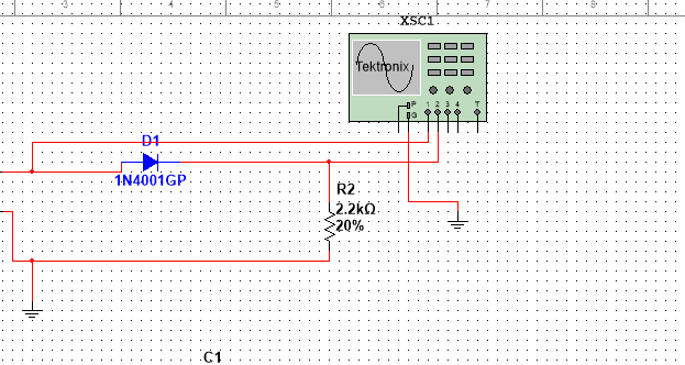
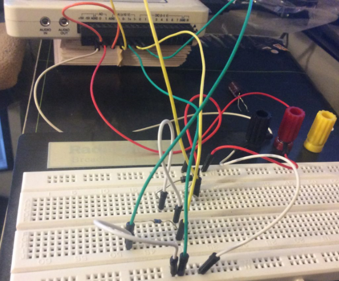
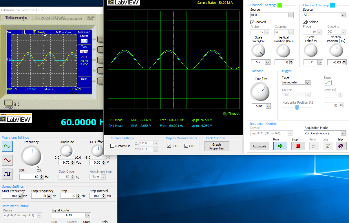
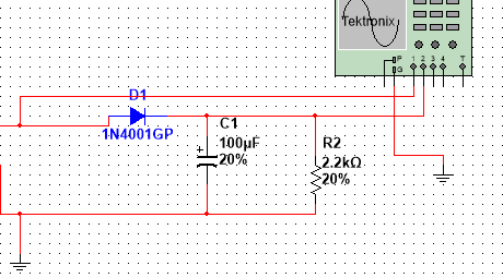
I have the myDAQ NOR, I have to build half rectified filter circuit with a resistance 2.2kOhm, I also use the multi-sim to confirm the measures of waveform. Everything goes well on Labview multisims Tektronix Oscilloscope compared to before I connect a capacitor 100uF my comparison heres:
The model is just the Diode with a series resistance 2.2kOhm, I'm not sure if the analog inputs to the LabView Oscilloscope are configured correctly this is the air I get:
This satifies my simple comparison on the Multisim circuit, since I came here for a few hours to play with probes analog input, I know that something is wrong out of these measures, I get.
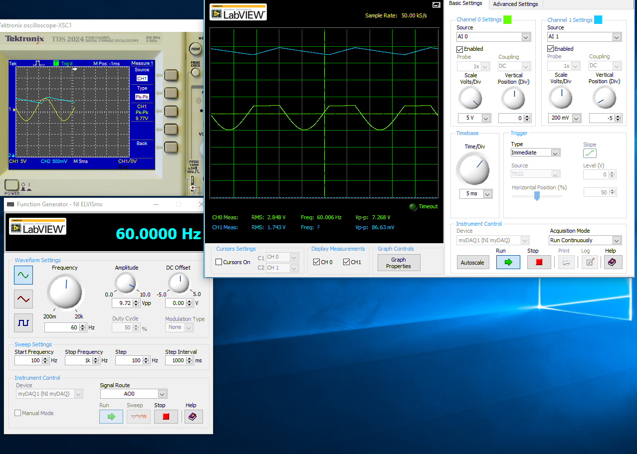
With a capacitor 100uF in parallel:
I think the question is how I inputs analog and STILL plugged, I'm not sure that this is where I would really like some help or any type of assistance. Once I get this set up right, I'll be able to take measures for the frequency, load DC, P - P Ripple voltage ripple and then move to a full-wave rectified circuit. I just started a course and received the myDAQ.
Henrik_Volkers wrote:
Compare it with the current specification of output of your myDAQ

Here is a link to the specification: http://www.ni.com/pdf/manuals/373061f.pdf
Henrik hit it on the head. The myDAQ can, at most, out 2mA with analog output. So, with a 2.2kOhm charge, which puts you in 4.4V without the diode. The led will also require an amount of current. According to my estimates, subject of 1mA (your pic is ~2.5V, divide by the 2.2kOhm to get ~ 1mA). You will see only that on the positive side of the sine wave as the diode blocks all the negative side.
The lesson here is to make sure that your outputs have enough power to do what you want. You can go to get a simple op-amp from digikey and use a follower of tension for editing the current upward. You will probably need another power supply or two (+ 12V and - 12V) to power op-amp.
-
Hi, I'm working on a project where there partly to measure resistance values in different parts of the circuit. Now, the company where I work currently at wants to get the NI USB-4065 USB. I use visual studio 2005 c# to develop applications and I need to know if I needed measurement studio or are there drivers (dll) just to get the values of resistance and General measures of circuit. I have need the controls or anything, just to programatically read the NI USB-4065 USB key values when I need the application.
Any help would be appreciated. Thank you.
Yes, you can have several NI 4065 DMM in your system. When you use the API OR-DMM, you open the handles separately for each DMM by using its name. His name can be configured inside the measurement and Automation Explorer (MAX).
In addition, you can go ahead and install OR DMM today. It is downloadable for free on ni.com. NOR-DMM (and most of the pilots NOR) supports the simulation. You go to MAX and create your simulated three 4065 s. Then you can start writing your program now. Since these devices are simulated, they will not return the real tensions (obviously) and that it won't react realistic hardware triggers if you use (obviously), but they are pretty close to the real deal to allow you to write a lot of code and become familiar with the API. No need to wait until you get the material - you can be really ready for it by using the simulation.
-
Measurement of Phase difference of audio - learning how to set the reference
I'm trying to measure the difference in phase between two audio inputs. (Left and right channel of my sound card)
Both are free running 1 kHz audio samples that come in and out of phase.
When the samples are in phase, everything seems to work fine and shows no phase difference.
However once that signals start to emerge from the +-10deg phase the result keeps jumping around.
It seems to be the fact that it is changing the reference to determine the phase.
When I view the phase of the output of a channel is a sawtooth waveform, from 250deg and then wraps round to-110deg
What I want, it's an entry set to 0 degrees and see the other inputs of difference of phase against it.
Is there a way to give a signal as being the reference or another strategy?
Thanks in advance for any help.
PLEASE NOTE THAT THE acquire.jpg IS ACTUALLY THE VI.
It wouldn't download like the vi. Please rename extension to acquire.vi to see.
Finally managed to find the problem.
Red rooster, I tried to replace your entries simulated with audio inputs card his real world and things turned out horribly.
It doesn't seem to be a translation between the two. (Perhaps because of my understanding of Labview garbage)
LabVIEW uses the internal reference of the DAQ cards in order to make phase measures.
That's what all use the phase VI of measure and which lack of cards not NI - DAQ.
That's what I thought that missed me first place but there's no way I can see simulations your own.
To work around the problem, I used zero crossing detectors in order to compare the time ahead or lagging behind the benchmark for the calculation of phase.
I got the core of the detector from somewhere on the forum but have lost the actual page. (my apologies to the author who deserves the credit)
Anyway, hope this hepls someone.
-
How can I set up a table of reference for comparison of the measure?
Hello
The configuration of my inspection VBAI code section indexes automatically through a series on the exposure time. The intensity of the image, to each exposure time, is compared to the parameters of current at the time of the exposure range. (This is due to the many colors of part) When both the parameter corresponds to the intensity of the image AND the exposure time, he acknowledged the best exposure time setting, and it stops and is then ready for inspection tests. Different pairs of time of exposure and intensity parameters are part of the code of the algorithm. When the new colors are added, the code must be expanded.
I would like to know if a reference table can be put in place so that the code finds the correct corresponding pair in the table. Then, it should only add rows to the table.
Thank you
I'm not sure that I fully understand what you want to do, but it looks like you might be able to take advantage of the new feature of table in VBAI 2012. With this, you can create two variables 1 d digital... one who is an array of values of exposure and the other which is an array of measures of intensity. In the part of the configuration of your control, you can either use two table operator not (to get the same index in each array), or you can use a step of the calculator to get exposure to acquire with time and intensity expected to compare to.
You can also use step INI of read/write on the last tab to update these variables of two table with values of exposure/intensity since an INI file is easy to update the INI and get your up-to-date without changin the inspection automatically set variables you need to add more combinations.
Hope this helps,
Brad
-
How to make a reference spectrum for spectral measurements in spectrometry optical ocean
Hello
I'm desigining a labview software for the Maya ocean optics spectrometer pro and the problem that face is I'm not able to make a correction of the base line as in the spectrasuit to the measurement process perform.
In spectrasuit we have the option as store dark spectrum and remove the dark spectrum, which actually acts as a reference I want to design the same way can any one help me?
Thanks in advance
-
The spectral measurement VI allow the reference value of 20 microPa dB
I want to show a FFT of sound pressure level in DB(a), where the reference should be 20-06 PA. All the Spectral measure of VI I can find using a 1.0 dB reference. The spectral measurement VI allow a reference to 20th-06 Pa? I have the Sound and Vibration Toolkit. Thank you.
Rick
In the Sound and Vibration Toolkit, there is a VI called Set dB reference. This VI will set the dB reference for your data for you or you can take a look at how that VI changes the attributes of the waveform and impliment the scaling on your own. Once your data dB reference is correctly adjusted the screw of the FFT should display the data with respect to this property.
Maybe you are looking for
-
Firefox crashes at startup, can not run except in safe mode
When I try to open Firefox, it crashes immediately. I can only run in safe mode. I have not installed just recently I can think that it would affect. Here's the latest crash report 5 IDs: bp-a0f9cb98-1e79-4ade-9313-4b8f32130320 bp-ce2412c3-4611-4586-
-
TD Ameritrade Streamer does NOT WORK with version 4.0
After you install version 4.0 of the Ameritrade Streamer Firefox did not work. The Streamer was going at the time of the 4.0 download
-
What is the cover/housing or the coating of the ThinkPad T540p?
Hi all I wonder where is the cover/box of the Thinkpad t540p? Is there any coating? I can't find this information on the Web site. I ask this question because I have a chemical sensitivity Multiple and plastic gives me problems. Thanks in advance!
-
Select start measurment only if the temperature is less than 26 ° C for 10 seconds
Hello I have a program for a measure of viscosity/temperature use DasyLab 12 I burn my brain to try to activate the measurment only if the temperature is less than 26 ° C for 10 seconds. Click on 'Start', then control the temperature, if the temperat
-
My mother-in-law uses her computer for 3 things: email, internet, and backgammon. She was very disappointed by his new computer because it has Vista with no Backgammon. The MSN version works well not look as good as the XP version. It would be unr