Measurement of frequency with the NI 9402
Has anyone successfully was able to measure the frequency in SignalExpress with the NI 9402 module? I have the 9402 connected to a tachometer (on a centrifuge) which puts a TTL signal. For now, I can get the light input line to work. (Right click on the project, acquire signals: DAQmx Acquire: digital input: input line.) When the tachometer completes the first round, light or the 'blip' lights indicating the sensor then goes back to the shore for the rest of the round. I would like to read the frequency of this "blip" instead. I can't understand the required parameters in Signal Express. I tried (right-click project, acquire signals: DAQmx Acquire: entry of meter: frequency) but maybe I do not have the correct settings. This centrifuge works usually between 0 and 3 hz. I have attached a picture of what I have. I am doing this correctly, with incorrect parameters? Or is there a better way to do this? I need to read Hertz over time. Thank you!
Hi Choover,
Even if you use the 0 meter to measure frequency, your singal acts at the door of the on-board clock source to measure the length (and thus frequency). This is why you must use PF1 to connect to the door of the meter. You can learn more about how DAQmx takes measurements of meter in any manual of cDAQ chassis: http://digital.ni.com/manuals.nsf/websearch/2C061605E17C7D04862578D200677B90
Brian
Tags: NI Products
Similar Questions
-
Measurement of frequency with the NOR-6221
Hello
I would use the OR-6221 to measure the frequencies of the order of 200 Hz to 12.5 Mhz.
Is this possible?
Can you guide me were to start?
There are notes of application with examples?
The required accuracy is not high 0.5 percent more or less...
Thank you
Rafi
-
Measurement of high frequency with the NI 9411
Hello
I would like to measure the frequency of a TTL signal with the 9411 OR in a cDAQ-9178 chassis. 1.6 at 48 kHz frequency range.
With examples of Labview digital frequency meter, it is not picking up on the signal. Any advice?
Anna
Hello!
After talking to an applications engineer of NOR, I realized that the input signal must be less than 5 v. In particular, the bass is between 0 - 0.8V and the top is between 2 - 5V.
Once I have limited input to this range, the module of frequency meter picks up on the signal very well.
Thank you
Anna
-
Measurement of frequency with CompactRio
Dear all
I have an anemometer which sends digital signals. I'm trying to analyze the signal to determine the speed of the wind.
I have one NOR cRio-9024 and NI 9205. When I connect the anemometer, it gives me some positives square rear tension (see attachment). I wonder if I could turn this to the readings of frequency because it is linear to the wind speed.
I tried to follow the link below, but my module does not have the option of digital Configuration specialist
http://digital.NI.com/public.nsf/allkb/C9088DFDF803CD8B862575F3007C40FD
or I should have another module OR who could measure the frequency of the signal directly?
I would like any ideas or suggestions. Thank you very much!
LabVIEW Newbie
-
Capture of frequency with the NI 9401 in cDAQ-9172
Hi all
I searched through all the examples and find the same results than my own code in Labview. So, I go back to my hardware to solve my problem. I use a digital tachometer that displays pulse with 2 wires (hot and ground). I connected these to the NI 9401 for 16 PINS for PFI 1 and PIN 3 on the ground. When I open the module through MAX, he reads the perfectly when hi and lo as well as count properly if it is placed in the location 5 or 6.
However, I try to use the frequency max task and the task fails to capture anything in the table. I get a time-out error, even if my tach is read correctly. I have attached my settings of the task. Thanks for any help
Your samples to read is set to 100. If all the samples of 100 are not available before the timeout is reached, you will get a time-out error. What is the frequency of the input signal? Maybe just try to read 1 sample on request first.
Best regards
-
Measures of constraints with the NI 9219
Hi all
I join this forum and I need bit of advise on measurement of deformation using NI 9219 with lab view.
I followed the procedure and settings to configure a virtual channel to strain under global virtual channel of NI DAQ mx.
I need some clarification on strain gauge measures:
1. If I use 1 quarter bridge configuration should I NI 9219 completion resistors?
2.i have ordered strain gauges, but I can imitate the calculations of strain with labview gauge using a variable resistor instead of active Gages? as I understand, it's strain gauges to change resistance when the force is applied.based on this notion if I use a variable resistor on one leg of wheatstone bridge and plot the data? all I want is to play with lab view until I get the real strain gauges. (will take a week to get deleivered)
3. affecting the internal Vex I think that I will not need to apply any voltage to the terminals of the bridge as the strain of installation window.i would just need to connect to the ends of the stone bridge of wheat to the PIN number 3 and 5 in the comment of 9129.please OR who...
I have to really thank and appreciate all of you for taking the time and reading/commneting on my post.
Kind regards
Ali
Hi Engr_tech,
9219 a resistance integrated half-bridge completion, but for quarter-bridge measures, it must rely on resistance measurements 2 son. It does not support the measures of quarter 3-wire bridge. I'm not familiar with the help of a variable resistor instead an active gauge so I can't comment on that. Looks like your #3 idea would work, although I'm not 100% certain. It will be unsupported, but it could work.
-
Looping/cycling through frequencies with the signal to create VI
Hello
I am trying to operate a PZT with a given signal (of a formula) and to save the output of the sensors. I use a PXI of NI 5421 to generate the signal and an NI PXI 5105 to record signals. I made the attached code that works well, however, I'd like to be able to the frequency and the number of samples (the number of samples is function of frequency) in the VI of signal to create loop so that I can scan a range of frequencies. Could you please help me. I can't find a way to control the frequency outside the edit in the Properties window.
Thank you
Casey
Sanjay-thank you
I just thought of it. I Redid the vi and when I ran an error that said come the input signal must be an integer value to a multiple of 4. I made a few simple changes to make and after that everything worked as expected. I guess that the entrance of waveform looked ok but not get operated by material, unless it is a multiple of 4.
Thanks for your help,
Casey
-
Frequency of measurement with cDAQ NI 9402 chopper
Hello world
I'm new in the world of the cDAQ and try now just get a frequency of a TTL signal output chopper. I confirmed 23 Hz frequency on an oscilloscope. It's a nice clean 5V square wave, but when I try to measure the frequency in labview using a VI (dig frequency of continuous measurement) example, it comes to expire. Trying to look at the entrance of the signal in express shows signal an incompatible digital signal that is around 3 Hz and clearly the result of the port being interviewed for entry too rarely. The final objective is to get this work with the labview vi PLL is a detector lock in the amplifier, but first of all, I have to be able to measure and to read correctly this frequency.
My hardware is a cDAQ-9174 with a 9402 OR for use with the digital input. I don't know it's important, but the 9402 module is in slot 3 and I'm on channel 0. The software is labview 8.2 with DAQmx 9.1. Is there some timing issue material or the definition of I'm missing here? Any help is greatly appreciated, thank you!
Hi Skaboss,
Counters have multiple terminals (source, the door in and out), which map to separate on your NI 9402 PFI lines. For the measurement of the frequency, the default input terminal depends on the method of measurement (low frequency, high frequency, wide range). Here's the relevant section of the NOR-DAQmx help (which is on the Start Menu):
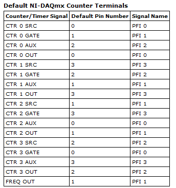
Connections of signals C series for counters
The following table lists the default input for various measures of meter terminals. You can use a different line of the PFI for one of the input terminals. To edit the entry PFI for a measurement, use channel NOR-DAQmx attributes/properties.
NEITHER 9402 and NI 9435 (4 channels)
Measure Ctr0 Ctr1 Ctr2 Ctr3 Number of edges Edges: PFI 0
County Executive: PFI 2Edges: PFI 3
Branch Count: PFI 1Edges: PFI 1
Branch Count: PFI 0Edges: PFI 2
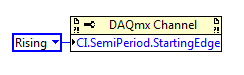
County Executive: PFI 3Pulse width measurement PFI 1 PFI 2 PFI 3 PFI 0 Duration/frequency measurement (low frequencies with a meter) PFI 1 PFI 2 PFI 3 PFI 0 Measure of duration/frequency (frequency with two counters) PFI 0 PFI 3 PFI 1 PFI 2 Duration/frequency measurement (wide range with two counters) PFI 0 PFI 3 PFI 1 PFI 2 Measure semiperiod PFI 1 PFI 2 PFI 3 PFI 0 Measurement of two-Edge separation Departure: PFI 2
Stop: PFI 1Departure: PFI 1
Stop: PFI 2Departure: PFI 0
Stop: PFI 3Departure: PFI 3
Stop: PFI 0Measure of position A: PFI 0
B: PFI 2
Z: PFI 1A: PFI 3
B: PFI 1
Z: PFI 2A: PFI 1
B: PFI 0
Z: PFI 3A: PFI 2
B: PFI 3
Z: PFI 0Alternatively, you can override the default with the CI. Freq.Term channel property.
Brad
-
Problem with the HP drivers Download Page
Don't know where best to post this topic.
I have problems with the HP driver download Page. Using the Chrome browser, I installed the HP product detection utility. Once installed, I admitted that it runs, and it correctly detected my HP computer and the details about this poster. A detail that he displayed was the guarantee being exceeded.
Since I had hardware problems and had to replace the hard drive and reinstall Windows, I wanted to make sure that my computer has all the HP drivers and software required. This information would not be displayed. At first I thought it was because I had an active browser add-on. I've disabled and reloaded the page. This is where I'm having the problem.
The product has been detected once more, but nothing happened when I clicked on the button search solutions for the detection of the product page.
You have found the difficulty that has the utility.
I never had a large measure of success with the utility unless I use Internet Explorer. I rarely use Internet Explorer.
-
I have a HP Pavilion 590PC and would like to know how to change the graphics card GEForce GT420 existing with the GE Force GTS450 and will there be a difference?
Hello
If you need improved video performance, then the answer is Yes. You will see the difference with the video intensive applications.
Review the performance of NVIDIA specifications. Look at the specifications of strip memory bandwidth and level of DirectX support. Also check this comparison.
The NVIDIA GTX 550 TI is priced in the same way to the GTS 450. GTX 550 it is a video card faster, compared to the GTS450. Look at this comparison.
Open your PC and a few measurement in parallel with the PCI-E x 16 slot to see how long of a video card will fit. The adjacent slot on the PCI-E x 16 slot must be vacant.
' HP ' how-to ' articles should be useful.
-
Calculated measure (OLAP language) of the calculated measure (Expression OLAP)
Hi, once again!
I need to create a calculated measure in the form of free type AWM (OLAP Expression, with the condition BOX) based on the results of another measure calculated again with the status of the CASE.
For example, I have a few basic measure number of type 'BM1', 'BM2', "BM3" . And I create a calculated measure "BM_AMOUNT" that returns a number if 'BM1' is not null or 0 with the expression:
CASE
WHEN BM1 = 0 or BM1 is NULL THEN NULL
ANOTHER (BM2 - BM3) / BM1
END
And then I create a different "BM_PT" calculated measure that returns points based on the value of the first expression:
CASE
WHEN BM_AMOUNT > 0 THEN 0
ANOTHER 20
END
Now, when I want to create the second expression I get error: XOQ-01958derived measure is a type of invalid data or data of any kind.
I found a way to work around this - I create first the measure with the NUMBER type and then change it to the expression of OLAP, and it works.
However, the problem is when I export the cube and that you want to import on another instance. Then, I get the same error for this measure "BM_PT" and impossible to import the cube.
The only way I've found is to edit the XML code and remove the measure, then create it manually as mentioned above (type NUMBER then change it), but it would be really nice if there is another way to knit this tour. This is so my question, is it?
* The example is just to help understand what I want to achieve and what is not correct.
Re: #2
If you use OLAP DML, if CUBE_DDS is the name of the cube and DOOD is the name of the measure then the expression to use in the formula of the OLAP DML is
_ . Try with CUBE_DDS_DOOD, CUBE_DDS_F0150, CUBE_DDS_DO0, CUBE_DDS_SF0213, CUBE_DDS_F0180 etc., in the formula.
In AWM, you can open the OLAP worksheet and check if the following expressions are valid by publishing a
> CUBE_DDS_DOOD DSC
order
Formula:
> If nafill(CUBE_DDS_DOOD,0) eq 0 then na to another ((CUBE_DDS_F0150 + (CUBE_DDS_DO0 + CUBE_DDS_SF0213) * 0.2) - CUBE_DDS_SF0213 - CUBE_DDS_F0180) / end CUBE_DDS_DOOD
-
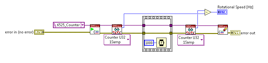
With the help of the meter from 6525 to measure the frequency: is there a more orderly way?
I am currently using the high speed on a module USB 6525 meter to measure the frequency of an object in rotation via a sensor hall-effect.
I was wondering if there was a simpler way / more effective this encoding than that?
Everything that I currently perform the current meter reading, wait a second, take another reading, and subtract one from the other. The result is the frequency in hertz.
Is there a way to get the 6525 to return the number / change County after 1 second?
Thank you
On the 6525, you have a country of the event and you can't make a measure of frequency.
-
VI to convert input signals NI 9402 in a RPM value, based on the frequency of the pulses
Hello
I'm looking for a VI convert an input signal NI 9402 in a RPM value, based on the frequency of the pulses. Is there such a thing that exists in the library of national instruments?
I run LAbview 2014 integrated control and monitoring on on a cRIO 9802 high performance integrated system with NEITHER 9402, 4 channels, 50 LV, LV TTL Module input/output digital, ultra high speed digital i/o for the cRIO module.
Any help would be greatly appreciated.
The easiest way is to use the FPGA to get the time between the edges of your pulse increase (shift registers to maintain the current situation and the time will be necessary). This will give you the period. If it's a single pulse per turn, then the number of laps is just 60/T, where T is the time in seconds.
-
Measure the frequency of the pulses PXI-6624
Hello. I work with a PXI-6624 and am interested to make measurements of pulsed frequency for frequency and duty cycle on its inputs using DAQmx.
When I go to create the virtual channel, however, I have error-200431:
"Physical channel selected does not support the type of measure required by the virtual channel you create."
' Asked the value: pulse frequency.
«You can select: frequency, period, pulse width, period of Semi, separation of the two edges, Position:...» »
Is this card really not capable of doing these measures of pulse frequency?
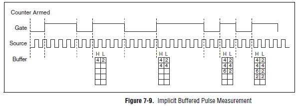
Yes, the "Pulse" (not to be confused with "Pulse Width") measure was introduced with STC3 of OR including CompactDAQ and X series devices.
Measuring the pulse:
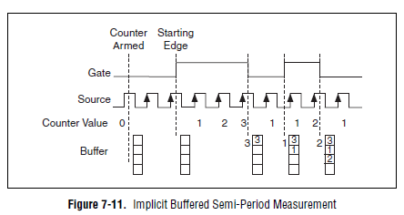
However, you should always be able to measure the frequency and the duty cycle on your card with a half measure:
The half measure:
The images are in the X Series user manual.
The difference between these two modes boils down to how the data is stored and implemented in buffer on the map - with the period semi method that the material does not distinguish between high and low samples and puts everything in a single buffer. However, if you start the meter on the song (see below the node property), then you would know the order of low and high samples in software, and are easy enough to calculate cycle frequency and the duty of this.
Best regards
-
High speed continuous measurement of encoder with sampling frequency of 1 kHz
I am able at all times the position of a linear encoder using a PCI-6602 counter card, and I need to know how to set up so that the counter rotating at high speed, but the data is inserted into the buffer at a frequency of 1 kHz. I am able suddenly to a hydraulic cylinder, and I am not concerned about the event recording to high frequency except to the extent where they throw off the number considerably if the equipment does not run fast enough to detect all the impulses of the encoder.
Now, I think is that the external sample clock signal control (routed internal pulse output counter) time rate whereby the equipment detects the impulses of the encoder and the rate at which it inserts data into the buffer. With a pulse 100 per inch encoder and a sampling frequency of 1 kHz, the extended final position of the cylinder is turned off by +/-0.15 inches, which is unacceptable.
I need calculate a speed of this information, so I prefer not to use software timed sampling to control this (it's more difficult programming for other reasons as well - several asynchronous measures). Any ideas on how to configure the hardware to count faster than the speed at which she inserts counties in the buffer?
OK, you're clearly on the right track here, so I will focus on some details.
1. How do you know that the +/-0.15 "differences are * measurement error rather than * error of movement? Why wouldn't be an accurate measure and a proposal which can vary slightly from the nominal value?
2. I wonder some all electric noise and defects that may produce false edges. The fact that the behavior was better by using a sampling rate limited (200 kHz) in the digital inputs may be that some of these flaws were so short that they were never captured.
I did a ton of work with the Commission to 6602 encoder and I can certainly confirm that count equipment is sensitive to the edges in a few tens of MHz. (I know its 80 MHz for edge counting, but I think I remember that it can be of the order of 20 to 40 MHz to accommodate the time of signal propagation extra of the quadrature decoding circuit).
A small point of clarification. You're talking about the speed at which the meter "works to. The value of count is a register whose value is changed completely by the circuit, * independent * of the sampling frequency. If you enjoy with material-clocked County in memory buffer or interrogation of software without buffer not a bit for circuits that increments / decrements the value of the counter register. (In other words, I am completely convinced that you would get commensurate with position end even if you took only 1 sample software-polled after the end of the move instead of sampling at 1 kHz all the way through.)
So, if the value of the counter is disabled, it is because the circuit detects producers of County of the edges that shouldn't be there. Something you can try is to set up digital debounce filter for input lines of the PFI corresponding to the encoder Source inputs and to the.
-Kevin P.
Maybe you are looking for
-
Facebook scrambled after mcafee upgraded via IE for remote access
After access remote mcafee update via IE, my yahoo account works on IE but only partially support the e-mail on FF (no work of buttons and you can not meet the emials etc.). my Facebook screen is also blurred and I can't access anime players on Anime
-
Laptop Compaq nc6320 & SSD and Windows 7
Hello.I need know nc6320 Compag:-compatible SSD drives?-Can I install Windows 7 on new SSD? Thank you
-
email attachments will not convert so that I can read in word
Open an email to weed an encrypted sound. Tried to use the word and windows solutions options to get it converted to word If I can read it.
-
Startup Repair, retains and will
System repair started, it is said, this may take several minutes, but it keeps the search for problems, for an hour already. Is there a time out for it, should I try something else? The people did not have system restore on. What happens if no failur
-
I use Windows Movie Maker but when I publish the movie I have a green horizontal band to halfway across the screen. Please can someone advise?