Measurement of high frequency with the NI 9411
Hello
I would like to measure the frequency of a TTL signal with the 9411 OR in a cDAQ-9178 chassis. 1.6 at 48 kHz frequency range.
With examples of Labview digital frequency meter, it is not picking up on the signal. Any advice?
Anna
Hello!
After talking to an applications engineer of NOR, I realized that the input signal must be less than 5 v. In particular, the bass is between 0 - 0.8V and the top is between 2 - 5V.
Once I have limited input to this range, the module of frequency meter picks up on the signal very well.
Thank you
Anna
Tags: NI Software
Similar Questions
-
Measurement of frequency with the NOR-6221
Hello
I would use the OR-6221 to measure the frequencies of the order of 200 Hz to 12.5 Mhz.
Is this possible?
Can you guide me were to start?
There are notes of application with examples?
The required accuracy is not high 0.5 percent more or less...
Thank you
Rafi
-
Measurement of frequency with the NI 9402
Has anyone successfully was able to measure the frequency in SignalExpress with the NI 9402 module? I have the 9402 connected to a tachometer (on a centrifuge) which puts a TTL signal. For now, I can get the light input line to work. (Right click on the project, acquire signals: DAQmx Acquire: digital input: input line.) When the tachometer completes the first round, light or the 'blip' lights indicating the sensor then goes back to the shore for the rest of the round. I would like to read the frequency of this "blip" instead. I can't understand the required parameters in Signal Express. I tried (right-click project, acquire signals: DAQmx Acquire: entry of meter: frequency) but maybe I do not have the correct settings. This centrifuge works usually between 0 and 3 hz. I have attached a picture of what I have. I am doing this correctly, with incorrect parameters? Or is there a better way to do this? I need to read Hertz over time. Thank you!
Hi Choover,
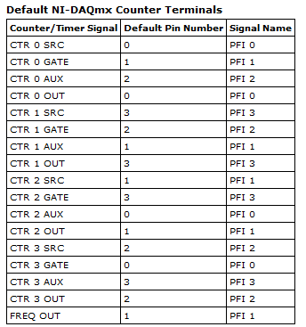
Even if you use the 0 meter to measure frequency, your singal acts at the door of the on-board clock source to measure the length (and thus frequency). This is why you must use PF1 to connect to the door of the meter. You can learn more about how DAQmx takes measurements of meter in any manual of cDAQ chassis: http://digital.ni.com/manuals.nsf/websearch/2C061605E17C7D04862578D200677B90
Brian
-
measurement of analog frequency with PCI or USB
I want to measure the frequency of a square wave 0 - 5V from zero to about 4 kHz permanently. I have to record the waveform, only get the frequency. The material at my disposal include:
(1) PCI-MIO-16
(2) 6062E DAQCard
(3) USB-6218
If none of these devices can do this? This seems to be a very common task, why can't I find the perfect example to do so. I'm not having any luck with the DAQ assistant. Can someone tell me a simple example?
You can also read the following link:
And look at the examples in the zip here
-
Capture of frequency with the NI 9401 in cDAQ-9172
Hi all
I searched through all the examples and find the same results than my own code in Labview. So, I go back to my hardware to solve my problem. I use a digital tachometer that displays pulse with 2 wires (hot and ground). I connected these to the NI 9401 for 16 PINS for PFI 1 and PIN 3 on the ground. When I open the module through MAX, he reads the perfectly when hi and lo as well as count properly if it is placed in the location 5 or 6.
However, I try to use the frequency max task and the task fails to capture anything in the table. I get a time-out error, even if my tach is read correctly. I have attached my settings of the task. Thanks for any help
Your samples to read is set to 100. If all the samples of 100 are not available before the timeout is reached, you will get a time-out error. What is the frequency of the input signal? Maybe just try to read 1 sample on request first.
Best regards
-
Looping/cycling through frequencies with the signal to create VI
Hello
I am trying to operate a PZT with a given signal (of a formula) and to save the output of the sensors. I use a PXI of NI 5421 to generate the signal and an NI PXI 5105 to record signals. I made the attached code that works well, however, I'd like to be able to the frequency and the number of samples (the number of samples is function of frequency) in the VI of signal to create loop so that I can scan a range of frequencies. Could you please help me. I can't find a way to control the frequency outside the edit in the Properties window.
Thank you
Casey
Sanjay-thank you
I just thought of it. I Redid the vi and when I ran an error that said come the input signal must be an integer value to a multiple of 4. I made a few simple changes to make and after that everything worked as expected. I guess that the entrance of waveform looked ok but not get operated by material, unless it is a multiple of 4.
Thanks for your help,
Casey
-
Fonts and icons in Photoshop still too weak in IPR systems high even with the last update!
Come on Adobe! Autodesk, Google, Piriform, Microsoft, Corel Draw and many others have already set the question put on the scale in high resolution systems.
Fonts and icons in the entire UI in Photoshop CC are still tiny after the last update, with the exception of drop-down menus. And the 200% scale in the experimental features that makes them too big. When are you going to fix this?
Someone else knows how to fix this? I noticed there is a setting in preferences-> interface, there is an option to change the user interface fonts, it goes from small to big, but he does nothing...
If you want to give your Adobe comments please use Adobe Feedback does site not this Photoshop family customer community forum
-
Entered digital high frequency to the FPGA could not be detected OK
Hello
We want to connect the CMOS camera with PCIe-7842R with SCB68 box to analyze the image in the FPGA. There are PCLK (pixel clock) signal (36 MHz) and 8 bits of data.
On the 1st, we write a test program to ensure that we can detect the PCLK correct which is attached as program.png. The program is very simple there is a loop timed with 80 MHz, which should be enough take 36 MHz signal. If the value of 8000 "Digital 2", we should have 3600 (+ -1) like "digital." The reason why we (+ -1) is that we have no synchronization, is supported in this test program. And we can get the right result in this configuration.
2nd part, connect us data to 8-bit on FPGA and we get a wrong result of PCLK. Even connect us only 1 bit (which is labeled as DIO1 program) data, the PCLK is disturbed, and we can't find out why. The configuration of the connector is attached as connector.jpg.
We tried to make 2 very distant digital signals, but are still not. We tried to change the cables connected between SCB68 and FPGA of SHC68-68-RDIO cable for SHC68-68-RMIO cable because we think she may have better armor. We have a better result but still bad.
Now, we put "Digital 2" 8000 and we have about 3400 ~ 3500 as 'digital."which is false.
Does anyone have advice or commands on this problem? I'm very appreciate your kind help.
Thank you.
-
How to measure and fill it with the same transparency?
for example the creation of a fill using Edit > fill with a random color and opacity in the fill dialog box, then later without the original on the color and opacity information but just the file, how can I do exactly the same fill and opacity again?
If you have a partially transparent layer and then use "layer > Layer Mask > transparency" to convert the full opacity layer and a mask.
This will give you the color of each pixel and the opacity of each pixel grayscale representation.
-
Bad data measured at high frequency
-
A measure of speed high speed with encoder in quadrature and NI 9401 on cDaq
Greetings,
We use an encoder in quadrature with 360 pulses/turn on the tracks (track A and B) and no trace of Z to measure motor speed at startup. Data acquisition, we use a NI 9401 in 9178 cDaq chassis and a pc with LabVIEW. The problem is that the start-up period is relatively short (less than 1 second), during which we measure speed as precisely as possible. The speed range is from 0 to 10000 RPM.
What type of measurement method that you would recommend.
Here are a few methods that we have already tried:
-Measure with DAQmx CIFreq--> high frequency with 2 counters: speed measurement, but with a very big mistake (+ 166 RPM).
-CIFreq DAQmx--> wide range with 2 counters: good speed data but more slow measurement,
-CICntEdges DAQmx (counting separated the two lanes, speed conversion): very incoherent speed data.
Thanks in advance for your help.
Matej
I would definitely say a 4, the measure of a low freq called option with 1 meter. (Frankly, I've never been
fond of this name because it is useful for freqs much higher than what I expect most people think "low freq".) This
is the method that I almost * always * use for frequency of counter measures. It works really well to capture transitional
variations in speed.
10000 rpm and 360 cycles/rev, you are looking at a maximum frequency of 60 kHz. The frequency measurement mode 1 meter
There will be 80 MHz internal clock by encoder cycle edges, then you will get more than 1000 strokes per measure. The point
that means only 1 number of quantization errors, you can expect<>
Further, you can average overall, say, 10 samples to you give even better accuracy and you could still be a data capture
rate significantly higher than the probable bandwidth of your mechanical system. (The average would just clean the jitter and noise and would not
Hide answer true mechanical characteristics).
-Kevin P
-
Portege R700-172 high frequency twittering
Hello
anyone experienced a high frequency of the Portege chirping. I admit just a few days. Twice I had such a sound and wonder what it is (it is not the typical fan noise.)? I disabled speakers, but this wans't ' the source of it t...It will be difficult to address this issue on the forum.
Look closely at what will happen in the future, and if this keeps happening again and again I recommend you contact the nearest Toshiba service provider and ask for help.
In general your Portege should bring up some strange noises. -
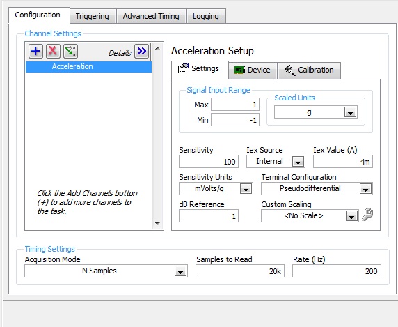
Noise measurement of an accelerometer with card PCI-4461
Hello world
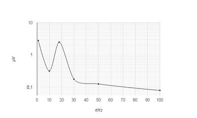
I'm trying to measure the noise of an accelerometer, except with a card PCI-4461.
First of all, I measured manually this noise with the help of a HP35665 signal Analyzer. I get something like this:
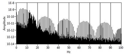
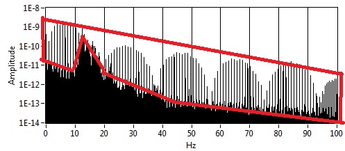
And now with LabView and the PCI-4461 map, I get this:
My question is: Whence this part? And how to remove it? (Since there is no with the signal Analyzer)
I'm using LabView 8.5.
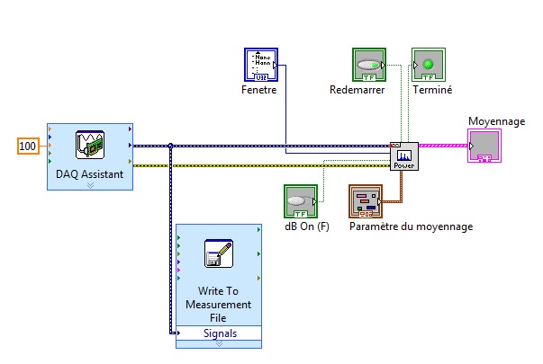
This is how I configured the DAQ acquisition:
and it's my VI:
Thank you in advance for help
Arthur
-
compare files with the same structure of channel / rename channel(-groups)
Hello
I have several groups ch with many channels in the file of each measure.
Now, I need to display/compare Channels 2 or more files of measures in a chart. (channel 'speed1' to the file 'measurement1' vs 'speed1' to the file 'GCA2' channel)
So I import 2 files in the browser und have the same structure of string twice. To distinguish between the channels of the two files I want to rename the channels by script and add the file name of the channel-group name.
Is this a common way to compare measurement data in files with the same channel names and structures?
In the affirmative. How can I make a script?
Thank you very much in advance!
Ski
Hi Ski-Fahrer,
each channel has a name of the institution.
Data.Root.ChannelGroups ("Name" or Index). Channels (Index or "Name"). Name
You can assign a new name like this:... Name = "NouvNom".
I don't think it is necessary to rename the channels. If you do not forget the files. If you want to rename something I only rename the ChannelGroups by adding a date or a serial number.
Kind regards
Philipp K.
AE | NOR-Germany
-
Hello
I just got my phone this week. I loved this day! I am just confused with some things...
First of all:
I have my email to work for me and I have a gmail icon just to mail on the home screen. Is there a similar app AOL mail? or is the AOL Search icon only downloadable icon to the home screen?
Second:
On my phone, there is a world high above with the #2 in the left of it... My sister and my brother has the exact same phone me as long as they don't have it. what it means?
THANKS FOR YOUR HELP!
 Nilda
NildaIf you use Gmail app. As much as I know there is no BB AOL application itself like Gmail app.
But you can incorporate into your AOL via BIS account (http://na.blackberry.com/eng/support/software/internet.jsp) and gmail account can be integrated in the same way. This way, your e-mail will be pushed the same corporate e-mail, without having to chk mailed on the app.
Can you be a bit more descriptive on your 2nd quest?
Maybe you are looking for
-
What can not run more than 2 screens on my Tecra R850?
Despite claims that the R850 (with Radeon graphics card) will be 4 screens, the best I can manage is 2. I am trying to connect 2 external LCD screens and continue to use laptop as another screen (3 in total). I did a lot of research, and even if I ca
-
Windows 'System performance' BLUE SCREEN
JEG far gentagne Ganga nedbrud af pc pga. BLUE SCREEN. Hvad kan/skal jeg gore for at blive debt problem kvit?
-
I want that my descriptive text of the icon on the desktop without a "shade of the color of the desktop setting out the text block.
-
My 25 character product key is not recognized, as well as the mass storage controller is missing.
two problems RY5U870-ImageSensor06 not recognized as mass storage controller is not found My 25 character product key is not recognized as mass storage controller is missing and a meesage RY5U870_Image Sensor06 is not compatible. I use a computer lap
-
Question about the attributes Active Directory and ACS 5.2
To authenticate on our wireless, our ACS server checks to ensure that a node is a member of a specific group of computers. When we disable the computer account, the continuous ACS server to spend despite the account being disabled the authentication