Measurement of resistivity with MyDAQ on TEC ca
Hello
I would like to ask for advice: we would like to measure resisitivity Peltier-elements. If we use the DC method, due to the cell voltage-Seebeck effect, we don't get the value of the true resistivity. The common method to use the measure of ca in the case of these devices. I would like to know if it is possible to use a device of MyDAQ for this task? As a first approach do us not need more precision, it would be more as a test of 'broken-element' (there is usually a significant change in the nominal AC resistivity value indicated by the manufacturer).
What would be the best way to make a simple measurement? What if I use an analog output of the MyDAQ lets say at 1 kHz, and I drive the Peltier element with this AC voltage source? I connect a resistance in the series, and I measure the AC voltage on that drop. After the results, I could calculate the current and the resistance of the AC of the Peltier element? Of course, I choose a resistance so the MyDAQ can drive the network.
What is your opinion, where to start?
Thank you!
Sounds like a good chance to learn more about these devices. In these conditions, I would do the same thing: try with what you have.
A quick glance at the plug MyDAQ it is clear that the current of the AO is limited to 2 my. I probably set the zone of OCCUPATION for about 2 V and use 1000 ohms in series with the Peltier device. That will keep the current in the 2 limit my. Two lines of AI to measure the tension on fixed resistance and the Peltier device. Then, you can calculate the unknown resistance.
If you were doing a production test or did the measure with a DC bias, I advise to use a transformer to couple the AC component in the CC line. This becomes a little more complicated to implement, but has much to versatility.
Please post after you have tried and let me know what you found.
Lynn
Tags: NI Software
Similar Questions
-
Measure the resistance with PXI DMM 4072 on different frequencies
Hi all
I tried to get on board various and unable to find solutions for that. I'm trying to measure resistance using NI PXI-4072 on frequencey 1 kHz, but not luck. When I try to use Agilent LCR meter I see the correct value of the resistance.
I've seen a few posts on this but don't have no satisfactory solutions.
In above post, someone said that I can use 4072 DMM OR digitizer, does not have a lot.
Can someone please provide the right path for me to solve this problem.
Thank you
Hello Puneet_K,
I checked the data sheet and the method of measurement described in the specifications of the NI 4070/4072 http://www.ni.com/pdf/manuals/371304g.pdf; indicates that the ability is measured using an alternating signal and select the test frequency range, for example 3 kHz, 1kH or 91 Hz. The resistance is simply measured using a DC signal, and it is often sufficient to measure the internal resistance of a battery. If you need a more flexible control for the measurement, you probably get a card like the function generator and then set a multimeter to measure the voltage and another DMM to measure the current and calculate the impedance of these values.
I hope this helps!
Kind regards
-Natalia
-
measure resistance with USB-6009
I am measuring the resistance of a photocell using the USB-6009 case. There is an option of "resistance" in the DAQ assistant, but it does not display the values on the right. Here's what I do:
Connections: GND - photocell - ai0
I'm really not sure if this is right, but I assumed that he could measure the resistance as a multimeter. I have not tried doing a divisor of tension and using the Ohm's law.
DAQ Assistant settings: I 'add channel' by using the more blue and choose "resistance". Then, I chose ai0 under USB-6009. I set the max and min values and read it all the time. First problem, playback is generally negative and it flickers a lot. I read about - 1.3 k when I do that with a k resistor 10 regular (not a photoresistor)
Obviously there is something wrong, but I'm very new to all this and cannot figure it out by myself. Any help would be much appreciated.
Thank you!
The 6009 cannot measure the resistance as a multimeter unless you can prove that a current as the wizard by default source is set to. In itself, it can measure a voltage. Then, use a voltage divider.
-
The REPORT CYCLIQUE with myDAQ measure?
Hi all
Sorry for my beginner question. Is it possible to measure the duty cycle with myDAQ? If Yes, could you give me some advice please how? I want to measure the temperature with temperature probe SMT 160-30 with duty cycle output. I tried the analog and digital inputs. In the case of the analog input, there is a problem with zero amplitude (error). If I use entry digital then output is 0 and Boolean variable 1 and I don't know how to proceed with the determination of the duty cycle. I use DAQ assistant so I will gratefull for the solution with the DAQ assistant.
Thank you very much
Pavel
What you need to do, is to capture a waveform analog (PWM signal). Then you perform a comparison on all data entered to see if it is greater than a threshold. A typical threshold for a 5V signal is 2.5V. That should translate into an array of Boolean. Use then Boolean (0.1) followed by the average. If you want a percentage, multiply by 100.
-
I'm working on a project with myDAQ requiring three RTD constantly reading.
Two of Thermistors are 3 wires, the other is 4 wires. I followed the tutorial on the RTD Web site with a difference - I connect the RTD to the analog input. The excitation current is supplied by the power supply 5V on the myDAQ. I measured the current to be 37.3mA. When I open the DAQ assistant and choose all the parameters, the resistance reading is a constant 124 ohms. I held the RTD in my hand, put it in ice water, and reading this has not changed. However, when I provided power to the RTD and checked the resistance with a multimeter, it read 115 and this resistance * fact * change when it is placed in ice water.
Can someone help me out here?
I couldn't see the guide that you linked, it seems that it redirected to this forum? If you were referring to the myDAQ, then you can use a 3 or 4-wire thermocouple, just in mode 2 son like that described in the article I linked. And Yes, this measure seems to be only possible between HI and COM, not between analog input + /.
-
How can I use 2530 b and 4065 to measure the resistance between two selected pins?
I want to be able to select 2 corners on a test with 2530 b set-up and measure the resistance between them with a 4065 DMM (PXI all). Ankles in question are each in blocks of 32 different poles, so I can match them in a double configuration 32 x 1 four or 64 x 1 if necessary. I can measure the resistance between several different pine sets as 0 on 33 pine pine, pin 0 at pin 34 pin 0 to 35 pin and pin 1 to 34 pin, pin 1 pin 36, etc.
I understand how to measure resistance between a given pin and Earth using the the 2530 4065/b using the wizard OR-DMM/Switch Express, but it is unclear if I can measure the resistance between the two pins of selected by different user. I am a newbie of labview, used to write things in c#, so it may be something very trivial (I hope).
Any ideas?
Thank you
-Russ
Hey Russ,.
I recommend starting with the following example (located in the Finder the example ('Help' to find examples):)
"" Material input and output"Modular Instruments ' OR-Switch" niSwitch Dmm Switch Handshaking.viBecause you use a scan list, you can simply drag the two connections to the same entry and then the switch will wait for the two to settle before you send a trigger of the DMM... problem solved. For example, to connect the CH1 to Com0 (DMM +) and CH93 to Com4 (DMM), then take a measure, then connect CH38 and CH120 to the DMM, you would use the entry list of scan to the following address:
CH1-> com0 & ch93-> com4; CH38-> com0 & ch120-> com4;
Note You can have as an entry in list of switch module scan. In addition, you can only have a single advanced analysis and a measure full per switch module.
-
The use of attenuators with myDAQ
So I try to use an Attenuator (from mini-circuits, BNC 50 ohm) output on the myDAQ for tensions in the microvolt range. However, rather than mitigate it, the signal of clips instead. I tried a unity gain buffer, but the signal still clips. I used just an Agilent FG and the Oscilloscope, and it worked then.
Anyone know how I can fix this problem so that I can use these attenuators on the myDAQ?
Thank you for your time.
Hello Mochipoo,
There are some limitations that you should consider before trying to drive this attenuator. A 50 Ohm 3dB Attenuator is designed to divide the amplitude of the voltage from a source of 50 ohms to 70.7%. It is basically a load of about 150 Ohms resistance.
-Your benchtop FGEN has an output impedance of 50 ohms, but the myDAQ AO is a much lower impedance (about 1 Ohm in DC). The voltage divider, you would get a lot less attenuation (150 ohms / [1 Ohm + 150 Ohm] ~ = 99%.)
-10V in this attenuator driving requires a lot of current (10V / 200 Ohms = 50 mA, in the case of the bench; 10V / my 150 Ohms = 67 in the case of AO myDAQ).
-AO myDAQ lines have current limits to protect against overheating and prevent violate the USB power specification. The limit is approximately 2.4 mA, so if you try to drive a 150 ohm load with her, you'll shake very low (approximately 0.3 V - 0.4 V).
-As you describe, you can buffer the AO myDAQ with an external amplifier line, but if you use the myDAQ +/-15V rails, you should be aware of their current limits (once again, included to avoid thermal damage or technical violation USB). Our specifications operational is +/-16 my symmetrically on +/-15V or 32 my on one of the rails. They work above that, but they have current limiters which will be deliver around 60-75 my. I suspect that's why you see your clip of signals in the buffer. In addition, several amplifiers have current limits internal between 20-50 my if they may not be able to drive much output in any case that.
If you just try to take small steps to exit, I recommend you build your own divider of resistance with impedance that will not engage the limiters of AO myDAQ (such as the total of 10 kOhm load). You can do the mitigation of the factor what you want with the ratio. If the output impedance that results is too high for what you're driving, you may refresh the split signal. Since you are not driving a heavy load, you won't have the problems of limitation of power.
In addition, be aware that there are two beaches of operation for the AO myDAQ: ± 10 v and ± 2V. They are the two 16-bit resolution, so you can get 5 x more small steps only by using the range 2V.
I hope it's useful. Good luck and let us know if you have any other questions.
Charles Y.
National Instruments
-
measure temperature pt100 with cRIO9211
I can measure the temperature with a pt100 in cRIO9211? I wanted to measure of 0 ° c to 100 ° c...
Can someone please show me how?
Thank you very much
Best regards
Hello
Thanks for posting your question on the forum of National Instruments.
Unfortunately, you can't have a RTD (generally with a PT100 probe) measure on a module 9211.
9211 module is dedicated to the use of thermocouples.
I suggest that you use a 9217 or 9219 rather (more information here).
I hope this answer will help you.
Best regards
-
Good wiring when using Bode Analyzer with myDAQ
Hello
I'm trying to measure the frequency response of a lowpass butterworth filter 4 pole.
I use the myDAQ and Bode Analyzer software.
How to wire AO 0 and AI 0 to measure properly?
My simple understanding tells me to connect AO 0 at the entrance of the filter and GOT 0 + to the output of the filter and HAVE 0 - to the mass.
This produces strange results, and I think that something is wrong with the wiring.
Am I supposed to use AI 1 +/-in a sense?
Thank you.
You will need to wire them HAVE 0 and AI 1. The Bode Analyzer resembles the input and output of the filter and the caclulates response of 2 analog inputs. Since the entry to the filter can come from any source, the myDAQ, the parser must read the value at the entrance as well. That's why DO 2 channels is necessary.
AO 0 and AI 0 + will be connected to the input of the filter. HAVE 1 + will be connected to the output of the filter. 0 - AND AI 1 - will be wired to ground.
-
measurement of current with usb-6009
Hi, my name is hung and I am a student in electrical engineering... I'm doing a thesis that the project using Labview and acquisition of data NOR UBS-6009 to simulate the function generator, Oscilloscope, Digital Microsoft (DMM)... and now I'm simulating DMM. I managed to measure the voltage and resistance which i use voltage divider method, but I encountered a problem with the current measurement. The problem is the USB-6009 to measure use the current, it measures an incorrect value. I tried to use the current CQI 0-20mA Sample.vi example but it always measures an incorrect value. If NI USB-6009 supports for the measuring current? Is there a way to measure the currents using USB-6009? Please, help me. This thesis project is so important for me. Thank you.
Hung,
Since you are a student in electrical engineering, I'll show you how to know the answers to your questions.
1. review the specifications for the USB-6009 case. In particular look at the specifications of analog input.
2. How would you measure current if you had only a voltmeter? Use the same method with the USB-6009 case. (Tip: apply the Ohm's law).
General comment: when using any measuring instrument, always consider maximum permitted values at the entrances so that the instrument is not damaged
and the measure is accurate.
Let us know how you do.
Lynn
-
measurement of current with usb6008
Hello
I use a PMT detector whose output signal varies from 0 µA to 100 microamperes, but must remain lower than 100 µA. I put a 100 kilo-Ohm resistor in the line signal and, using a voltmeter, I can measure the voltage at the terminals of the resistance and calculate the current. I would replace the voltmeter with my USB6008. However, when you use a differential pair of channels to measure the voltage on each side of the resistance, the current wells USB6008 and affects the signal.
Is there a way to measure current without affecting the signal?
Kind regards
Oliver.
Oliver,
The 6008 sheet indicates that the AI input impedance is 144K ohms. Far too low for what you're trying to do. If you're stuck with the help of the 6008, I would consider using an instrumentation amplifier (AMP02 comes to mind http://www.analog.com/en/amplifiers-and-comparators/instrumentation-amplifiers/amp02/products/produc...)
to build a celled amplifier with a gain of 1 to act as a buffer. Input high impedance which does not load your source microamp, a lot of training for the 6008 entry.
-
Measures of constraints with the NI 9219
Hi all
I join this forum and I need bit of advise on measurement of deformation using NI 9219 with lab view.
I followed the procedure and settings to configure a virtual channel to strain under global virtual channel of NI DAQ mx.
I need some clarification on strain gauge measures:
1. If I use 1 quarter bridge configuration should I NI 9219 completion resistors?
2.i have ordered strain gauges, but I can imitate the calculations of strain with labview gauge using a variable resistor instead of active Gages? as I understand, it's strain gauges to change resistance when the force is applied.based on this notion if I use a variable resistor on one leg of wheatstone bridge and plot the data? all I want is to play with lab view until I get the real strain gauges. (will take a week to get deleivered)
3. affecting the internal Vex I think that I will not need to apply any voltage to the terminals of the bridge as the strain of installation window.i would just need to connect to the ends of the stone bridge of wheat to the PIN number 3 and 5 in the comment of 9129.please OR who...
I have to really thank and appreciate all of you for taking the time and reading/commneting on my post.
Kind regards
Ali
Hi Engr_tech,
9219 a resistance integrated half-bridge completion, but for quarter-bridge measures, it must rely on resistance measurements 2 son. It does not support the measures of quarter 3-wire bridge. I'm not familiar with the help of a variable resistor instead an active gauge so I can't comment on that. Looks like your #3 idea would work, although I'm not 100% certain. It will be unsupported, but it could work.
-
Help, please! Experiment to measure the resistance of the contacts in the relay contacts
Hello
I am completely new to Labview and have been asked to try to use the software and hardware to develop a VI to measure how the relay contacts contact resistance deteriorates with thousands of cycles. I have succeeded in one NOR cDAQ-9172 containing NI 9219 and NI9472 modules interface and can access them through the DAQ Assistant.
What I want to know is, how do I activate the relay I test and turn off using a pulse and keeping a count of operations and at the same time a measurement (this can be in each cycle of 100 or 1000) and save it in an ASCII data file?
All I have at the moment is the documentation of OR and a book titled Labview for engineers and scientists by John Essick, who I work slowly through.
It's such a difficult task VI?
Best regards
Andy
You can have a digital task as an analog input task running on the same chassis. You just turn the digital output of the cycle the relay and read with your analog inputs.
DIO most did not have enough current to drive a relay, then you want to get a digital stamp which can provide enough power for your relay.
Oh and check out the free online training modules
Introduction of 3 hours
Introduction of 6 hours
Bases LabVEW
Paced self-study for students
Self Paced Training beginner to advanced, required SSP
LabVIEW training Wiki
OR learning
Getting started with products OR -
Measures of CSR with SCXI - 1104 C + SCXI1300?
Hello
I have a module SCXI - 1104C for monitoring of asymmetric tension. I know that the SCXI module has entered differential only, so I assumed that I would need to connect each each negative terminal to ground.
However, I have noticed that if I connect Signal - SCXI_ChassisGND and Signal + SCXI_Ch0 +, I always get the correct reading. Reading fleet when I disconnect Signal - SCXI_ChassisGND.
Who am I observe here? Can I use the SCXI - 1104C for CSR measures, reliably connecting Signal - to ChassisGND?
Thank you!
Hello JKSH,
Consider the connection to the SCXI-1104 where...
CH0 + is connected to the Signal.
CH0 - is connected to anything
It is an unsecured configuration where Ch0 - is just floating to what voltage it was finally. It's probably somewhere around chassis ground because it was finally connected to the chassis ground. However, if you have touched the Ch0 - with tension at random, your measurement would be disturbed and a wrong level.
When Ch0 - is connected to a reference voltage instead, we guarantee level and can acquire valid tensions.
I hope this helps!
-Eric E.
-
Measurement of frequency with the NI 9402
Has anyone successfully was able to measure the frequency in SignalExpress with the NI 9402 module? I have the 9402 connected to a tachometer (on a centrifuge) which puts a TTL signal. For now, I can get the light input line to work. (Right click on the project, acquire signals: DAQmx Acquire: digital input: input line.) When the tachometer completes the first round, light or the 'blip' lights indicating the sensor then goes back to the shore for the rest of the round. I would like to read the frequency of this "blip" instead. I can't understand the required parameters in Signal Express. I tried (right-click project, acquire signals: DAQmx Acquire: entry of meter: frequency) but maybe I do not have the correct settings. This centrifuge works usually between 0 and 3 hz. I have attached a picture of what I have. I am doing this correctly, with incorrect parameters? Or is there a better way to do this? I need to read Hertz over time. Thank you!
Hi Choover,
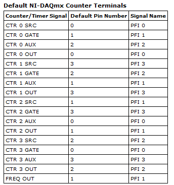
Even if you use the 0 meter to measure frequency, your singal acts at the door of the on-board clock source to measure the length (and thus frequency). This is why you must use PF1 to connect to the door of the meter. You can learn more about how DAQmx takes measurements of meter in any manual of cDAQ chassis: http://digital.ni.com/manuals.nsf/websearch/2C061605E17C7D04862578D200677B90
Brian
Maybe you are looking for
-
When I use the App Store icon on my iPhone 5 to attempt to update an app, it evokes the wrong ID. Apple to make it worse, it doesn't give me any option to change the Apple ID to the correct. I have disconnected and back again for both the iCloud and
-
Can I stop a separation of two edges with infinite time-out?
Hello! I use the example VI: "soul two Edge Separation.vi ' (see the Archives of this message) with a USB-6251and NI a timeout that is infinite because I Don t know when I need start a new measurement. With the features I need to stop the DAQmx VI "D
-
Miss me the drivers of usb 3.0 controller host for the hp Pavilion dv6 - 7013cl.
We recently purchased a HP Pavilion dv6 - 7013cl, and I installed Windows 7 Ultimate on it and went through the process of acquiring all the necessary drivers. However, the drivers for the AMD USB 3.0 host controller (x 2). The hardware ID is as fo
-
I just plugged my Apple G Drive (external drive) to my Laptop from Microsoft. Driving light - ON (It works fine on my MacBookAIR) EXTERNAL HARD DRIVE on the laptop computer of Microsoft Vista- EXTERNAL - UNRECOGNIZED HARD DRIVE. Help? I tried the dri
-
At startup I get the following error message: "cannot load or launch C:Users\Mike\AppData\Local\Temp\msuospuwo.exe specified in the registry. Make sure that the file exists on your computer or remove the reference to it in the registry. I tried to r