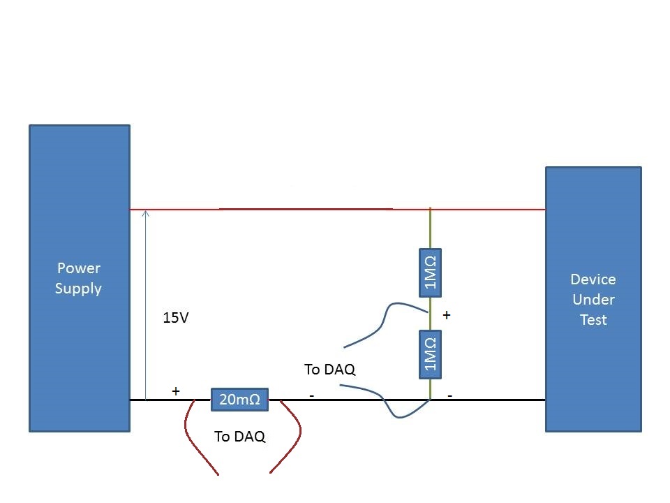
Measurement of the current rail voltage > 10V
Who am I to measure the current and voltage on a 15V supply rail. (Here's a copy of my circuit attatched) I use an acquisition of data USB-6225 and Lab View,
I have my camera to test connected to a power source. I connected two differential channels to the acquisition of data, one for the current and the other for the voltage.
I understand that data acquisition is unable to manage more than 10V so I use a voltage halfway through the voltage divider. When I run the action, the indicated current is incorrect. It shows the 10A when it should be about 500 my.
When I reduce the tension on the power supply 10V, it everything works fine, so I think that its got something to do with the limit of 10V.
Please can you advise how I can connect that places correctly?
Do it this way.
Tags: NI Software
Similar Questions
-
Measure the current and voltage using DMM sharing a port
I want to measure pressure several times on a pcb, where I connect the ports of digital multimeters to the card using simple cards. Switching between the different voltages is done using simple. If the black port of DMM (the second from the top photo) is connected to the Earth to give the measure correct volt.
And then I want to measure current through different lines. The problem is here. Given that two measurement types share a port, how do I get the correct voltage and current measurement? The second port of top would be grounded, so I can't use the method of measuring the voltage across the line through a resistance with a known value, since then the second port must not be connected to the ground. How can I use the current state of the DMM measurement? How measure current? Are there examples of this? Tried looking through manuals, but could not find the good starting points.
so I can't use the method of measuring the voltage across the line through a resistance with a known value, since then the second port must not be connected to the ground.
On all of my games to test I have to mux my land of the signal along with the salvation of my signals.
All my mux test sets are set up for the topology 2-wire because there is no other way to do it without the weak side of switch also.
-
measurement of the current usb or 6009
I'm trying to trace the evolution of a CCCV charger while it loads a 60V lithium-ion battery. I know that the charge rate is (1/6) C and the nominal capacity of the battery is 26Ahr resulting in a current of 4.33 has during this constant stage. I have the NI USB-6009 case and that e/s analog devices is estimated at 50 Ma, so I can't connect a thread of the charger directly on the device OR. I was thinking of buying a CT that connects directly to the material NOR and run the (+) lead from charger through the CT, as it charges the battery. What is the best way to go with the flow for a complete charge cycle? What are the other options to draw current developments?
A CurrentTransformer will work with current alternative...
A CT compensated with element Hall (research LEM) can measure AC / DC...
I'd look for a Hall Allegro current sensor... has a galvanic isolation output, and the output is the input range 6009.
-
Measurement of current and voltage USB-4065
I have an application where I need to measure the direct current and the voltage. The current and voltage will be stable if the measures do not need to be simultaneous. I would use a USB-4065 to the two measures. I've seen the kb indicating the voltage inputs must be disconnected when the measurement current. The current inputs must be separated for a measure of tension?
Hi Collin,
I think that you are referencing this knowledge base. After a few tests, and worked with the R & D group, it seems that the effects of input connections are perceived during the passage of two ways. When the current entries are connected, a less accurate voltage reading occurs. As such, please disconnect the current inputs for a measure of tension (as well as disconnect with tension when taking a measurement of current entries, who you know).
-
Column filtering for the current year measure
Hello
I'm blocked up with the question, we have a report of three tables D1, D2, and F1. Where D1 is of time dimension. We now report D2 and F1 with action, and the report is placed on the dashboard which is having the guest of the year.
F1 is joined with dimension D2 and D1 time as well, the requirement is in the report we measure column say X should always show the values for the current year, while others displayed according to the prompt values... In short, I want to show the column to measure for the current year, even if the user selects the value of prompt for year earlier and it must not change the values.
Please let me know, how to get there.
Thanks in advance
I am able to do this by following steps.
- I created a column in the MDB layer with similar to above said Srini case statement.
- Then I made the logic level of the time dimension column at ALL. So obiee ignores / filter join with the dimension of time to this measure, and the measure will always displays the data from the current year according to the case statement.
- If I did not this measure to all levels at the logical level, it's not working to the dashboard, when we change the year with the previous year it shows null values or zero according to the instruction box.
Thank you.
-
Measurement of the conductivity of the ground
Hi all
I'm trying to measure the conductivity of the ground using the Wenner table method. The attached photo is meant. I have a Board that generates an alternating voltage. The tension is provided in the ground using two socs (a round plate, partially buried in the ground and tied behind a farm tractor). Between these two points, I have an another two plowshares to measure the potential difference between these two points. Regarding the measure, I will need to measure the current voltage power and the potential difference. I use USB-6215. I put a known resistance in series along a leg of the alternating voltage. The idea is to measure the voltage at the terminals of the resistance (and so I can get current) given that USB-6215 is unable to measure current directly.
Now, my question is, in my view, a simple. I got confused on the connection I need to use. I know that I need to use differential measures to measure both the current and potential difference. However, referring to the guidelines for field wiring of NOR have (http://zone.ni.com/devzone/cda/tut/p/id/3344), I do not know if my case is considered updating the Earth or floating signal source.
Tips are appreciated!
Hi Lan 78,
Is based on the signal of your signal.
I therefore recommend differential connection.
However, there are a few things you need to know:
1. ensure that the voltage at the terminals of resistance exceeds 10V.
2. 6215 is a bus isolated, no channel-to-channel isolation. Therefore, if you measure a large voltage on several channels, he probably break down of the device.
3 bus isolated from 6125 is 30Vrms. ensure you that it does not exceed this requirement.
Sincerely, Kate
-
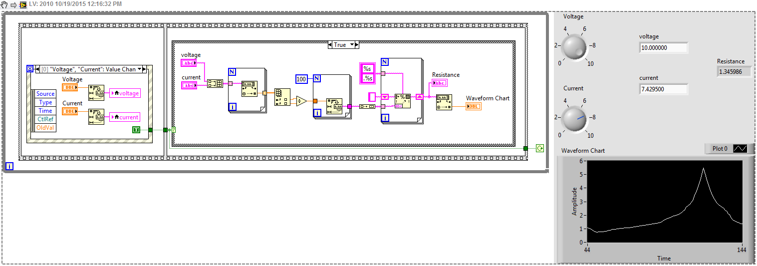
Hey someone create a labview program that uses the current and voltage to find the resistance. I also need a chart and buttons for aesthetic purposes. PLS HELP A GAL!
COME ON GUYS. HELP A GAL JAVA!
HERE YA GO, GAL.
-
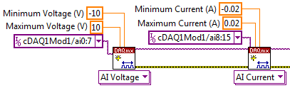
NEITHER 9207 reading current and voltage at the same time channels
I have a cDAQ-9178 chassis USB-three cards NI 9217 RTD, three cards 9263 0 - 10V and one the output OR 9207 16 channels analog card. What I m trying with this kind of things, is to read all the analog input channels (information of transducer, temperature, pressure, etc.) and adjust my controls to process with the analog output channels.
My problem at the moment is the following:
When I create tasks with DAQmx VI:s, how to create a task that reads current and voltage on the 9207 channels at the same time?
When I created a task for RTD-channels (16), a task for the outputs analog 0 - 10V (12), a task for the analog input 4-20mA (8) and a single task analog 0 - 10V input (8) I get an error-50103. I think it s because the tasks of current entry and voltagge are trying to use the same CAD at the same time and LabVIEW informs that "The specified resource is reserved. Tasks are to leave so that the analog output task starts first, then I merged all clusters of the error and the rest of the task are started by an order to current input-> input-> RTD input voltage. I get this error after the current enter task started and enter voltage task begins.
Because I m new on the LabVIEW and stuck in that time, I wanted to try the forum to find answers. I tried to find if someone else was having the same kind of problem, but with a quick search, there was none. I m in a bit of hurry, so I apologize if West a subject with a happy for that and I missed too much according to me.
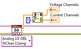
Really, the best way to do it is just adding 8 channels of voltage at a task, then 8-channel current, somewhat like this:
Then spread over different channels when you read later:
It should run without error. It always is multiplexed to sampling, but it will be much faster to create two separate tasks. There will be between 2ms (mode high speed) and 52ms (mode high resolution) between each playback channels, but it will still be much faster than the permutation of the tasks.
-
I/o current or voltage check with the switching matrix
Hi all
I want to use a switching matrix to test current and voltage of a control cabinet. For this, I have a voltage of the injector, injector current, a voltage measurement and measurement of currents from one side of the matrix (side line) and a 20 lines by I / O test. Is there a way to check (with a hardware or software solution) that we are ready for a test voltage or current in automatic mode.
The ideal would be to have a physical key indicating that we are testing the right card, but if the operator uses the wrong card, I would check it is not injected + 24V-on entry to an entry card 0-20mA current.I wish you turns me on!
Best regards
Vincent
Vincent,
Some approaches for you to consider:
1 Add a resistor or a few resistors to each card. Measure the resistance before applying all power to the i/o lines. The code of the resistance (s) to identify the class of Council (current or voltage) and rank (if applicable). Simple jumper on the unused pins of the connector can also be used.
2 measure the input impedance (or at least the resistive component) before turning the power on. An input voltage device probably has a high input impedance while the current input device has a low input impedance. It could detect and reject some devices with resistance to entry incorrect installed.
3. use a camera to determine which device is connected. (This should satisfy your request to be informed!)
4. you can replace the operator with a robot, but the robot would still need to use something like 1, 2 or 3 to identify the boards.
5. use edge configurations physically incompatible connectors/card so that the cannobe Board connected to the tester bad.
Lynn
-
Measurement of current and voltage on Agilent B1505A
Hi all
I'm learning to program the Agilent b1505A using LabView. I want to just start with a simple measure of a voltage supply and reading/measure of the voltage and current.
I was able to analyze the data and apply tension without and the problem. However, I can't understand how to check the voltage and the current. I can get it only to record one or the other.
I don't know how to know everyone is with Flex Agilent controls. When we look through the manual, I see that there is a CMM order that sets the mode of operation of EMS measure. I put it in mode 4, which measures both, but it still does not work.
Anyone who is familiar with the use of LabView to parameter program Agilent analyzers?
I got my code and the manual of the order of Flex of Agilent.
Thank you.
I think I found my problem!
It is in the FMT command that specifies the format of data output.
Thank you.
-
Can SCXI 1102 measurement of current and voltage signals simultaneously?
This may be a simple question, but I have a pair of moisture sensors that output 3 x 0-10 Vac @ 10 my max of signals that will be connected to a test loop that will have also a pair of sensors of flow as 2 x 4-20 my output signals, and I need to know if I can connect all four sensors on the same card of SCXI 1102 with endings of 1300 block , or if I need separate maps for the voltage and current signals. I am also looking at extra material for the other sensors, so I can have a different card if it will do the job better.
Thanks in advance!
BBalmforth Hey!
If I understand your description of the system you want to measure tension through the moisture sensors and known for flow sensors simultaneously.
Absolutely, this can be done with the 1102. In the pilot DAQmx can we individually select the channels to read the voltage by the moisture sensors, and then choose the appropriate channels to read the current of the flow transducers.
Let us know if there is something else you need said.
Happy holidays!
-
2 power supply: voltage increment on one when the current research on the other?
OK, so I work with 2 power supplies E364X Agilent. I have a unit with a door and drain that I do apply power. With the door I am applying 1.5V & .3a current limit, the drain I do a request 9.5V & 1 has current limit. What I'm trying to do, is to increase the tension of the door while controlling the current Drain and have the increments to stop when the Drain current comes down to .5A +/-50mA. I guess I kind of two questions. I use a state machine, the first iteratino defines the PS for the desired parameters (works fine), the next two iteration is supposed to accelerate the Power Supply Gate Voltate with small increments, check the current reading of power drains to see if it falls in the interval given, otherwise the increase continue, check again and so on... I'm having a problem with the part of increment as well as checking for the current game. I was thinking maybe I need to use a flat sequence or something along that line. Any help would greatly be apprecaited
For #1 supply, you should just have the voltage itself inside the loop. It would probably not hurt thanks to additional error checking just in case (you can then give up if there is an error). The rest can probably not stay outside the loop.
-
I can not get the voltage measured by the voltmeter.
Hello
When I use the VI "Cont Acq & voltage graph - write data to the file (PDM) .vi" to view the NI PCI6251 voltage, the voltage is of approximately - 5V. However, the voltage I measured by the voltmeter of the channels on PCI 6251 is about 0. 3. also, when I use another VI to show the voltage, it is of approximately - 5V too. I don't know what the problem is. Thank you very much.
-
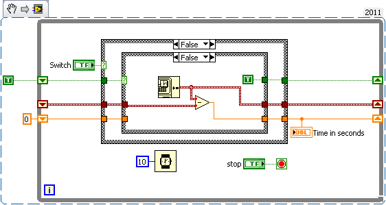
Hi all
I'm new to labview.
I want to measure the time of the duration of the current coming from the entrance of my input of data acquisition channel and use that time to make the decision.
How to measure how long to wait?
Thank you!
If you use DAQ as a guest, you can take the time system (will blink times). So when the switch must be high to start the countdown and stop it once it becomes low.
Time in the seconds indicator gives you the time interval between the action of switching
Good luck
-
Differential measurement across the ground of the card NOR referenced output.
Hello guys,.
I have a question, our pure curiosity.
I use map of USB6212 to apply a sinusoidal signal of 10V to a game to the top, then measure the tension between charges.
I'm attching here a simple diagram showing the system. The implementation can be modeled as a combination of RC - r series
Note that I'm also measure voltage R2 in differential mode. Now that I am after is exact phase of monitoring between the two voltages (according to the RC and the R2).
My question: is the correct diagram? I mean - is it OK to measure the voltage across R2 in differential mode with attached as such polarization resistors?
It is one of the lines through R2 is already at AOGND. And AIGND and AOGNd are already connected inside the card, it will be then introduced errors?
or does not at all?
Thanks guys, will be grateful for a quick solution.
You can do this but the differential mode does not have much. Your signal source is single ended. The voltage at the terminals of R1 - C can be measured in different ways. It really is meaningless to measure the voltage across R2 differently because one end is connected to the Earth. Polarization resistance, Rb, are not necessary in this case because the low enough impedance DC railways exist at all entrances.
What I would do, is make two measures ended up alone. AO1 measured on a single channel (AI0). Measure the R1 - R2 junction on the other channel (AI1). Then the input voltage is AI0, the voltage at the terminals of R1 - C is AI0 - AI1, and the current is AI1/R2. You will need to enjoy fast enough that the time between the different measures does not contribute too much to the phase error. It depends on your frequency of signal and eligible errors. Look at the charts of a waiting time to page 2 of the NI USB - 620 x specifications for more information on how to compromise between the speed, accuracy and multichannel source on measures resistance.
Lynn
Maybe you are looking for
-
I recently bought an external HD Seagate 1 TB to use with Time Machine on my iMac for mid-2011. I have never used TM before, but I have read and looked at some tutorials up to the point where I knew what to do. The HD has been recognized, I initiated
-
New e-mail window no longer opens automatically (as previously)
I've upgraded to the latest version of Thunderbird about 4 weeks back. (Don't know which version I used). Since then the new e-mail window does not open automatically when I seek to determine the folders and decide to do a right click on a file and s
-
How the auto join a jabber chat room
Does anyone know how auto join a jabber chat room when the account becomes available, I have not found the way, and whenever I go online I have to join the chat room. 9.1 messages Thank you very much
-
I have phoned me yesterday by an Indian man who said he worked for microsoft and that my PC has been infected and he could fix it. stupidly, I followed his instructions which led me to a site called AMMYY.COM. After that I pressed the icon "Download
-
Failed 801 META-INF/RDK. SF: File too big SF
Hello I recently started to test my application in release mode, and I encounter an error during the download of the application. The error message is: result::failure 801 META-INF/RDK. SF: File too big SF It seems that I share a similar problem as