Measuring the current.
Hi all
I'm new to labview.
I want to measure the time of the duration of the current coming from the entrance of my input of data acquisition channel and use that time to make the decision.
How to measure how long to wait?
Thank you!
If you use DAQ as a guest, you can take the time system (will blink times). So when the switch must be high to start the countdown and stop it once it becomes low.
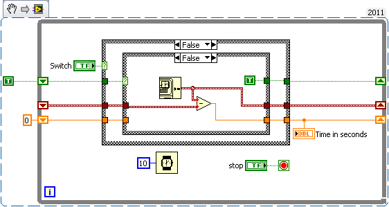
Time in the seconds indicator gives you the time interval between the action of switching
Good luck
Tags: NI Software
Similar Questions
-
Measure the current and voltage using DMM sharing a port
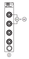
I want to measure pressure several times on a pcb, where I connect the ports of digital multimeters to the card using simple cards. Switching between the different voltages is done using simple. If the black port of DMM (the second from the top photo) is connected to the Earth to give the measure correct volt.
And then I want to measure current through different lines. The problem is here. Given that two measurement types share a port, how do I get the correct voltage and current measurement? The second port of top would be grounded, so I can't use the method of measuring the voltage across the line through a resistance with a known value, since then the second port must not be connected to the ground. How can I use the current state of the DMM measurement? How measure current? Are there examples of this? Tried looking through manuals, but could not find the good starting points.
so I can't use the method of measuring the voltage across the line through a resistance with a known value, since then the second port must not be connected to the ground.
On all of my games to test I have to mux my land of the signal along with the salvation of my signals.
All my mux test sets are set up for the topology 2-wire because there is no other way to do it without the weak side of switch also.
-
SMU, used for the measurement of current
Hello
I need to measure current in the range 5 to exit 10uA by a current source PIN. I would have usually connected PXI4065 on this PIN and measured current. But in this case the current to be measured is low.
I have EMS 4130, which has high accuracy of current measurement to 200mA range (0.03%+0.02)uA.
Can I use the current part of the EMS (CH1) measurement to measure current? What should I activate CV outputs (Hi = 0V) who appears in the soft front panel?
Or just without activating the outputs I can measure the current sink. The program of flexible panel displays current measurements, but I don't know if the EMS can be used like that.
Thank you
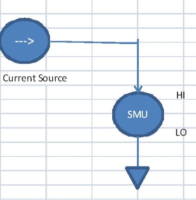
Not sure NI SMEs, as I have not had the chance to use it yet. SMU of Agilent could be used this way, so I guess with OR as well. You must use out SMU in constant voltage source / I measure mode. Would you say the SMU to hold the voltage at 0V, and allow current to the sink (or source) as necessary to maintain this 0V output.
-
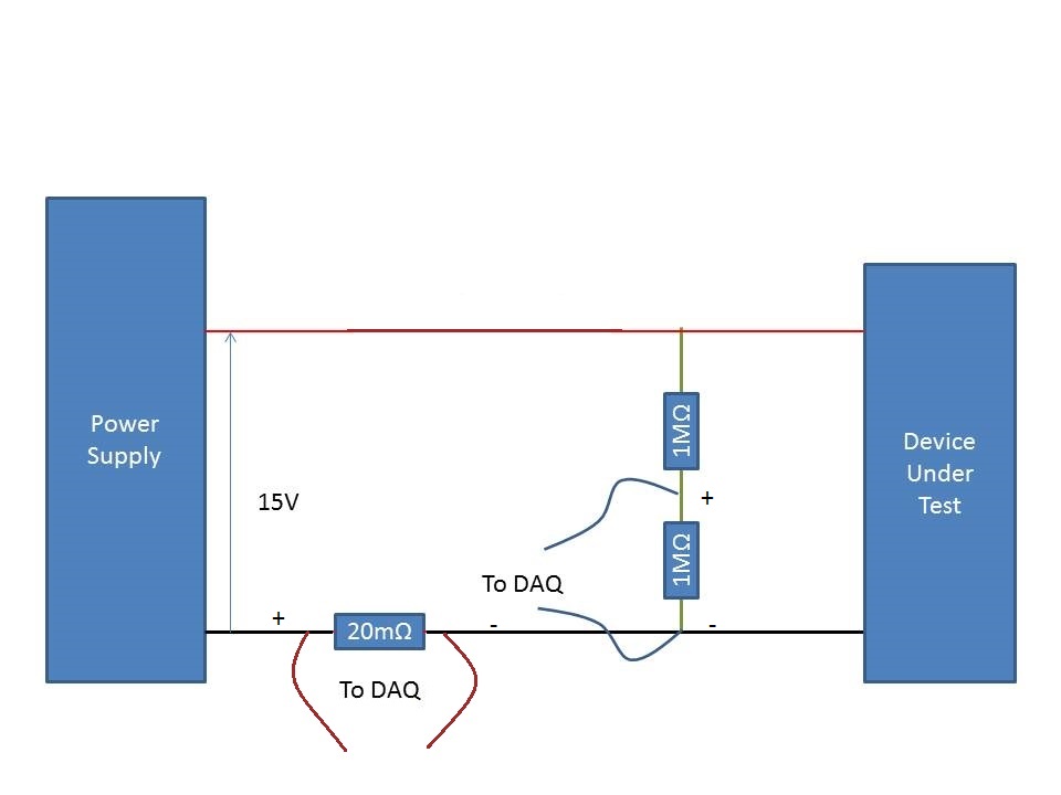
Measurement of the current rail voltage > 10V
Who am I to measure the current and voltage on a 15V supply rail. (Here's a copy of my circuit attatched) I use an acquisition of data USB-6225 and Lab View,
I have my camera to test connected to a power source. I connected two differential channels to the acquisition of data, one for the current and the other for the voltage.
I understand that data acquisition is unable to manage more than 10V so I use a voltage halfway through the voltage divider. When I run the action, the indicated current is incorrect. It shows the 10A when it should be about 500 my.
When I reduce the tension on the power supply 10V, it everything works fine, so I think that its got something to do with the limit of 10V.
Please can you advise how I can connect that places correctly?
Do it this way.
-
Measure the resistance with PXI DMM 4072 on different frequencies
Hi all
I tried to get on board various and unable to find solutions for that. I'm trying to measure resistance using NI PXI-4072 on frequencey 1 kHz, but not luck. When I try to use Agilent LCR meter I see the correct value of the resistance.
I've seen a few posts on this but don't have no satisfactory solutions.
In above post, someone said that I can use 4072 DMM OR digitizer, does not have a lot.
Can someone please provide the right path for me to solve this problem.
Thank you
Hello Puneet_K,
I checked the data sheet and the method of measurement described in the specifications of the NI 4070/4072 http://www.ni.com/pdf/manuals/371304g.pdf; indicates that the ability is measured using an alternating signal and select the test frequency range, for example 3 kHz, 1kH or 91 Hz. The resistance is simply measured using a DC signal, and it is often sufficient to measure the internal resistance of a battery. If you need a more flexible control for the measurement, you probably get a card like the function generator and then set a multimeter to measure the voltage and another DMM to measure the current and calculate the impedance of these values.
I hope this helps!
Kind regards
-Natalia
-
measurement of current with usb-6009
Hi, my name is hung and I am a student in electrical engineering... I'm doing a thesis that the project using Labview and acquisition of data NOR UBS-6009 to simulate the function generator, Oscilloscope, Digital Microsoft (DMM)... and now I'm simulating DMM. I managed to measure the voltage and resistance which i use voltage divider method, but I encountered a problem with the current measurement. The problem is the USB-6009 to measure use the current, it measures an incorrect value. I tried to use the current CQI 0-20mA Sample.vi example but it always measures an incorrect value. If NI USB-6009 supports for the measuring current? Is there a way to measure the currents using USB-6009? Please, help me. This thesis project is so important for me. Thank you.
Hung,
Since you are a student in electrical engineering, I'll show you how to know the answers to your questions.
1. review the specifications for the USB-6009 case. In particular look at the specifications of analog input.
2. How would you measure current if you had only a voltmeter? Use the same method with the USB-6009 case. (Tip: apply the Ohm's law).
General comment: when using any measuring instrument, always consider maximum permitted values at the entrances so that the instrument is not damaged
and the measure is accurate.
Let us know how you do.
Lynn
-
Measurement of current with NI6250
Hello
I use the 6250 OR for certain analyses of analog input. In addition, I want to measure the current that I supply to the unit under test. The current is about 300 my.
I thought to use a shunt at 2 ohms resistance, so lowering the supply voltage of 0.6V and not having not too low-voltage measures. I intend to adjust the votage of 9.6 V power supply to get 9V after the shunt resistance, because I'm supposed to provide.
1. any comments or better suggestions for this?
2. I will calculate the current by measuring the voltage on the resistance. The question is I will use 2 unique inputs or differential input?
3 you are looking for in table 4-3, page 4-12 of the M Series DAQ - user manual, I see an application of a differential input voltage. There, they put 2 pull down of the resistance to Earth. I do as well? Can't I just apply the 2 lines of resistance, directly at the entrance of diff?
4. am I suppose to connect the ALWAYS to my power supply GND?
Thank you
Rafi
In your case, the differential is the way to go. You don't need resistance more bias from (drop) current if your PS is connected to (A) MASS somewhere anyway.
-
How to detect the duplex and the current speed of the Ethernet card?
Hi, is there a tool to measure the current Ethernet card speed and duplex? I remember we had one for XP, but it does not work on Win7.
Any thoughts?
Specifically, I need to make sure my router and my NIC to work together without duplex mismatch.
Thank you
You will never see these actual speeds anyway. They are all theoretical maximum speeds. The only way to find your actual speed is a test of speed through your Internet access provider. Frenchie
-
How do you measure the NI 9505-"meaning current"?
I have a cRIO module 9505 and a closed loop current control FPGA program is roughly based on the help file OR: ...\examples\CompactRIO\Module Specific\NI 9505\Current Loop\Current loop - .vi NI 9505 (FPGA).
In both cases, and in my program, reported current (node of FPGA IO 'current sense") is an integral part of the control scheme, but I don't know units or how the number is measured. (The documentation leaves a bit to be desired)
The following comment in the file example FPGA 9505 confused me:
"The AI Trig is used to trigger the current sampling. Sampling occurs at
half the cycle PWM time (big time). There are 9 clock cycles, in this example,
from the time a trigger is sent until the current is actually sampled. Therefore, a
trigger is sent 9 clock cycles before the desired sampling point. »From this comment, it seems that the current I/O node sense is back from the instantaneous current. However, because the signal from the motor control PWM, the current during the time must always be the same. A signal PWM is either on or off. If I only trigger a reading over time, my duty cycle should be relevant, right? So, how would this function loop control? Either "current" value is not instant or I understand the purpose of the "AI Trig" boolean.
Second, how the number of cycles of clock between the trigger and the "current sense" read is known? The comment says exactly 9 clock cycles. I know that the FPGA and RT are deterministic, but how a programmer can know the trigger with this amount of precision delay?
Thank you
Ethan
-
Column filtering for the current year measure
Hello
I'm blocked up with the question, we have a report of three tables D1, D2, and F1. Where D1 is of time dimension. We now report D2 and F1 with action, and the report is placed on the dashboard which is having the guest of the year.
F1 is joined with dimension D2 and D1 time as well, the requirement is in the report we measure column say X should always show the values for the current year, while others displayed according to the prompt values... In short, I want to show the column to measure for the current year, even if the user selects the value of prompt for year earlier and it must not change the values.
Please let me know, how to get there.
Thanks in advance
I am able to do this by following steps.
- I created a column in the MDB layer with similar to above said Srini case statement.
- Then I made the logic level of the time dimension column at ALL. So obiee ignores / filter join with the dimension of time to this measure, and the measure will always displays the data from the current year according to the case statement.
- If I did not this measure to all levels at the logical level, it's not working to the dashboard, when we change the year with the previous year it shows null values or zero according to the instruction box.
Thank you.
-
To measure the pressure using a pressure transducer that provides the analog current output 4mA-20mA
I wanted to acquire the current analog signal which varies from 4-20mA using NI 9207. I tried in 2 ways.
method 1 - created an input channel current analog & used a reading Vi to acquire it. How can I give the channel connections in this...
method 2 - using NOR-DAQ Assistant, I put the channel connections and I got Amplitude versus time graph. She also gave negative values. Can I do this way which is easier? How can I solve the problem
First attachment belongs to the 1st method
Second attachment belongs to the 2nd method
-
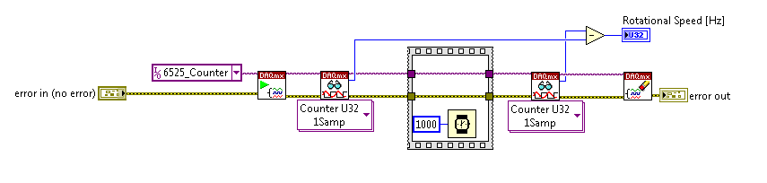
With the help of the meter from 6525 to measure the frequency: is there a more orderly way?
I am currently using the high speed on a module USB 6525 meter to measure the frequency of an object in rotation via a sensor hall-effect.
I was wondering if there was a simpler way / more effective this encoding than that?
Everything that I currently perform the current meter reading, wait a second, take another reading, and subtract one from the other. The result is the frequency in hertz.
Is there a way to get the 6525 to return the number / change County after 1 second?
Thank you
On the 6525, you have a country of the event and you can't make a measure of frequency.
-
See block labeled "digital data" in my attachment for reference. Currently, we can consider that the point of digital data for the current time step (it is removed before the following appears). However, I like it showed all the samples in the table as in the example that appears on this link under "digital waveform control":
http://zone.NI.com/reference/en-XX/help/371361H-01/lvconcepts/fp_controls_indicators/
Thanks a lot for your suggestions! I am new to Labview, so I appreciate your help.
Hey westerman111,
If you are looking to produce your display includes information of the previous steps of Solver solution, you'll need to buffer the previous data. How to implement this in a loop of Simulation of design by & control uses the Memory.vi under control design Simulation & > Simulation > utilities > Memory.vi. It will allow you to save previous information generated in the simulation for letter simulation environment.
I've attached an example that should help you get started using the Memory.vi.
I'd also sure that what you are trying to achieve is suitable for the control loop & Simulation. I know you said that you were new to LabVIEW, so I wanted to make sure that you went to sea in the right direction. Is there a particular reason, why you use the control loop & Loop Simulation instead of a standard time or a forum? The loop control design simulation & is unique in that it calculates the solution of a dynamic system to a no prescribed time and the ODE solver. It also provides tools to interact with the model you solve during execution. However, if you are looking for measurements (instead of the simulation of the dynamic model) and data acquisition I advise to use the standard features of LabVIEW.
Here are a few useful references for the departure with the two LabVIEW Control Design and Simulation Module.
Tutorial: Introduction to Simulation (Control Design and Simulation Module)
http://zone.NI.com/reference/en-XX/help/371894G-01/lvsimhowto/sim_h_gs/
Getting Started with LabVIEW
http://digital.NI.com/manuals.nsf/WebSearch/ba2fb433a7940e7a862579d40070cc2c
-
Measurement of current and voltage USB-4065
I have an application where I need to measure the direct current and the voltage. The current and voltage will be stable if the measures do not need to be simultaneous. I would use a USB-4065 to the two measures. I've seen the kb indicating the voltage inputs must be disconnected when the measurement current. The current inputs must be separated for a measure of tension?
Hi Collin,
I think that you are referencing this knowledge base. After a few tests, and worked with the R & D group, it seems that the effects of input connections are perceived during the passage of two ways. When the current entries are connected, a less accurate voltage reading occurs. As such, please disconnect the current inputs for a measure of tension (as well as disconnect with tension when taking a measurement of current entries, who you know).
-
best way to measure the thermistor
Hello!
We are looking for a solution for measuring temperature thermistor. I've read the material resources OR recommend for the thermistor measures.
Can you give me some ideas other alternatives for usable material temperature through resistance (we would use the default configuration, excitation of 2.5 Volts and a resistance of 5 + thermistor). So we need something capable of giving 2, 5V output and to measure the tension caused falling across the thermistor.Would be a NI USB-6009 suitable for this task? I guess that the resolution is not enough maybe?
Another option might be cheaper with a USB-GPIB interface Keithley 2010 multimeter, but in this case what should we use as a reference of tension?Thanks for the tips!
I want to second opinion to Henrik about repeatability in high resolution. Measures of temperature with Thermistors are particularly difficult. You have to worry:
- Auto-echauffants because of the power generated by the excitation current
- Time to balance the thermistor and electronic
- Stability of the excitation source
- Stability of the measuring device
In general, if you want something more than about 1% reproducibility, things start to me interesting. Of course, it's what makes it fun to do.
If you go the road of the sound card, remember that while most modern computers have quite high resolution a/d (sometimes up to 24 bits at 96 kHz) converters, you must watch the noise figures to get what you can actually solve. Off-board solutions (e.g., M - Audio Delta 44) will give you the best numbers of noise, since the ADCs are isolated from noisy inside your computer.
Good luck and have fun.
Maybe you are looking for
-
Satellite C660 back from repair - no WLan now
I recently got my laptop after a faulty screen repaired.When I turned it on it did not recognize my wifi, I tried to connect to it in the control panel (network and sharing Center), but nothing showed up. I also tried pressing Fn/F8, but it works mor
-
MacBook pro how to get rid of the guest in the toolbar user?
I have a macbook pro (OX El Capitan 10.11.3) and that you have noticed my name at the top right and I don't want it here, how do I get rid of him?
-
SharePoint Server 2010 and list of sorting/filtering
It is possible to sort or filter a list SharePoint is based on more than one column, without having to export to Excel?
-
How can I get my unlocked email, since he's are blocked?
so its been 2 days and still no resolution Tech eventhough say there is. my email address has been blocked, can't seem to get it unlocked... have not really solved as work important information are saved in folders and emails.
-
Where can I buy replacement Windows Vista support?
Microsoft used to sell the Vista reinstallation CD. M/S used to sell records re - install for a ridiculous price. I can't find the link to order one any where. Can someone help me?