Measurment LVDT DC with CompactDAQ
Hello
I am currently working with reading as a result of an LVDT for a project that the present model is the DC LVDT Omega LD620-25
According to the data sheet's model requires a voltage of 10-30 v and a maximum current of 25ma
http://www.Omega.com/pptst/LD620.html
with regard to the available data acquisition modules: the NI 9237 and the 9220 OR by using a module compactDAQ
as the NI9237 has an internal output of 150mW obtained maximum current is 15ma, simply use?
the 9220 OR will be used for the acquisition of data but provides no port of excitement!
as for the solution another I thought using an AC adapter / CC of normal 12Vdc 100ma with a variable pot or a circuit voltage divider to provide the necessary tension
but I have several concerns with respect to the Earth circuit. in this system, I will have two independent reasons!
What will be the best solution to connect the LVDT module to the 9220 OR and provide a source of external excitation?
Thank you
Hello ghattas.ak
Consider the NI 9218. It can provide 12V exictation to ~ 50 mA per channel and read 5 or output 10V DC LVDT. To use this excitement 12V, 9 - 30V power supply must be connected at the Vsup pins. As you said, you can also use the 9220 OR with external excitation. The NI 9237 measuring range of +/-25 mV/V does not cover the 5 or 10 v output sensor you.
See you soon,.
Izzy O.
Product Support Engineer
National Instruments
NI.com/support
Tags: NI Hardware
Similar Questions
-
measure temperature pt100 with cRIO9211
I can measure the temperature with a pt100 in cRIO9211? I wanted to measure of 0 ° c to 100 ° c...
Can someone please show me how?
Thank you very much
Best regards
Hello
Thanks for posting your question on the forum of National Instruments.
Unfortunately, you can't have a RTD (generally with a PT100 probe) measure on a module 9211.
9211 module is dedicated to the use of thermocouples.
I suggest that you use a 9217 or 9219 rather (more information here).
I hope this answer will help you.
Best regards
-
Measurement of voltage and the voltage with CompactDAQ display?
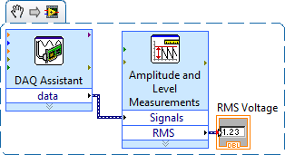
OK, I just got my CompactDAQ hooked up with two modules (9225, 9239) and am able to simple single-phase voltage (120 VAC)... I connected an indicator, and it gives me shooting random sine wave values and what I'm looking for a simple voltage reading. MAX and the DAQ assistant both work very well to the configuration task and I can see the signal in there.
I dug through the DAQmx, watched functions in the knowledge base and have searched here without any real results. I also downloaded the EPM resource kit, but it's tools for further on the road... It seems to me that this should be simple crazy, but maybe I go too hard or just looking is not in the right place? I would greatly appreciate a point in the right direction!
Thank you!
Chad
With the help of... Windows XP (SP3), LabVIEW 2009, cDAQ-9174, 9225, 9239.
Chad,
When you say "simple voltage readout" are you referring to the effective voltage of the AC signal? If Yes, you can use the Express VI 'Amplitude and level measures' to calculate the desired value.
Hope this helps, otherwise if specify you what you are looking for a little I will try again.
~ SimonH
-
220VAC measured with CompactDAQ?
Hi all
I'm building a testbed automated, where I need to measure both single-phase (120 and 277VAC) and two phases (208/240V ca... I am aware that nobody calls him two phases, but that's what you are actually measure... anywho) I have single phase works fine as seen in VI 'DAQ_Sample3', but when I try to apply the same logic to two legs of power my output is only sends me data for a leg. I went and added two other channels so it measures both legs and two amp clamps... I can connect the DAQ assistant for a graphical output and it shows all four readings, but when I'm trying to transition to power VI it will only calculate one leg. I have attempted to combine the signals from several different ways, but have not had a bit of luck to get a result that passes the test of reasonablilty... someone who knows a bit more on this taking a glance at the VI I for two can live (DAQ_Sample4-2ph) and point me in the right direction?
Thank you!
Chad
OK, well I finally realized what was going on... Apparently If connect you single phase (one leg and one neutral (120/277VAC) or legs (208-240 VAC) you must measure between a0 and a1 (differential measurement) and not on each leg to land is represented here...) http://zone.NI.com/DevZone/CDA/tut/p/ID/8216 For some reason any if you measure single phase 208-240 VAC and try to measure each leg down the numbers aren't right. I am now in a position through a channel and my numbers are dead on with my parser.
As a side note, that power might want to add more information to this series of videos... http://sine.NI.com/NIPs/CDs/view/p/lang/en/NID/208111 and comment on the actions of power for all single phase (120/277VAC and 208-240 VAC) should be taken on a single track on the module 9225. .. .or include a wiring diagram specific for various applications.
A big thank you to all who tried to help! I hope that this thread will save someone some time and frustration.
THX
Chad
-
Measures of CSR with SCXI - 1104 C + SCXI1300?
Hello
I have a module SCXI - 1104C for monitoring of asymmetric tension. I know that the SCXI module has entered differential only, so I assumed that I would need to connect each each negative terminal to ground.
However, I have noticed that if I connect Signal - SCXI_ChassisGND and Signal + SCXI_Ch0 +, I always get the correct reading. Reading fleet when I disconnect Signal - SCXI_ChassisGND.
Who am I observe here? Can I use the SCXI - 1104C for CSR measures, reliably connecting Signal - to ChassisGND?
Thank you!
Hello JKSH,
Consider the connection to the SCXI-1104 where...
CH0 + is connected to the Signal.
CH0 - is connected to anything
It is an unsecured configuration where Ch0 - is just floating to what voltage it was finally. It's probably somewhere around chassis ground because it was finally connected to the chassis ground. However, if you have touched the Ch0 - with tension at random, your measurement would be disturbed and a wrong level.
When Ch0 - is connected to a reference voltage instead, we guarantee level and can acquire valid tensions.
I hope this helps!
-Eric E.
-
Measurement of frequency with the NI 9402
Has anyone successfully was able to measure the frequency in SignalExpress with the NI 9402 module? I have the 9402 connected to a tachometer (on a centrifuge) which puts a TTL signal. For now, I can get the light input line to work. (Right click on the project, acquire signals: DAQmx Acquire: digital input: input line.) When the tachometer completes the first round, light or the 'blip' lights indicating the sensor then goes back to the shore for the rest of the round. I would like to read the frequency of this "blip" instead. I can't understand the required parameters in Signal Express. I tried (right-click project, acquire signals: DAQmx Acquire: entry of meter: frequency) but maybe I do not have the correct settings. This centrifuge works usually between 0 and 3 hz. I have attached a picture of what I have. I am doing this correctly, with incorrect parameters? Or is there a better way to do this? I need to read Hertz over time. Thank you!
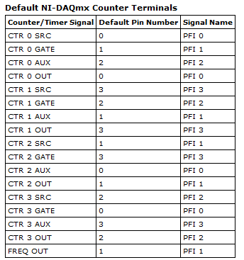
Hi Choover,
Even if you use the 0 meter to measure frequency, your singal acts at the door of the on-board clock source to measure the length (and thus frequency). This is why you must use PF1 to connect to the door of the meter. You can learn more about how DAQmx takes measurements of meter in any manual of cDAQ chassis: http://digital.ni.com/manuals.nsf/websearch/2C061605E17C7D04862578D200677B90
Brian
-
measurement of current with usb-6009
Hi, my name is hung and I am a student in electrical engineering... I'm doing a thesis that the project using Labview and acquisition of data NOR UBS-6009 to simulate the function generator, Oscilloscope, Digital Microsoft (DMM)... and now I'm simulating DMM. I managed to measure the voltage and resistance which i use voltage divider method, but I encountered a problem with the current measurement. The problem is the USB-6009 to measure use the current, it measures an incorrect value. I tried to use the current CQI 0-20mA Sample.vi example but it always measures an incorrect value. If NI USB-6009 supports for the measuring current? Is there a way to measure the currents using USB-6009? Please, help me. This thesis project is so important for me. Thank you.
Hung,
Since you are a student in electrical engineering, I'll show you how to know the answers to your questions.
1. review the specifications for the USB-6009 case. In particular look at the specifications of analog input.
2. How would you measure current if you had only a voltmeter? Use the same method with the USB-6009 case. (Tip: apply the Ohm's law).
General comment: when using any measuring instrument, always consider maximum permitted values at the entrances so that the instrument is not damaged
and the measure is accurate.
Let us know how you do.
Lynn
-
consecutive measurements or 6221 with good timing
OR PCI-6221 allows us to measure some transient phenomena. Our wish is to change the sampling frequency, while measurement is in progress and keep the time stamp on the right. For example, we measure for the first ten seconds with 100kS/s, for the next 90 with 1000kS/s and for the next 900 with 10 s/s.
Is it possible to use the internal clock to do this? If yes how?
Dear Kypros
Technically, you can implement a solution to this request by creating a train of pulses from a meter out. You can change the frequency of this output of cunter on the fly and correlate your acquisition of this counter. Feel free to look at the examples in our developer zone. You can find this useful example:
-
High speed continuous measurement of encoder with sampling frequency of 1 kHz
I am able at all times the position of a linear encoder using a PCI-6602 counter card, and I need to know how to set up so that the counter rotating at high speed, but the data is inserted into the buffer at a frequency of 1 kHz. I am able suddenly to a hydraulic cylinder, and I am not concerned about the event recording to high frequency except to the extent where they throw off the number considerably if the equipment does not run fast enough to detect all the impulses of the encoder.
Now, I think is that the external sample clock signal control (routed internal pulse output counter) time rate whereby the equipment detects the impulses of the encoder and the rate at which it inserts data into the buffer. With a pulse 100 per inch encoder and a sampling frequency of 1 kHz, the extended final position of the cylinder is turned off by +/-0.15 inches, which is unacceptable.
I need calculate a speed of this information, so I prefer not to use software timed sampling to control this (it's more difficult programming for other reasons as well - several asynchronous measures). Any ideas on how to configure the hardware to count faster than the speed at which she inserts counties in the buffer?
OK, you're clearly on the right track here, so I will focus on some details.
1. How do you know that the +/-0.15 "differences are * measurement error rather than * error of movement? Why wouldn't be an accurate measure and a proposal which can vary slightly from the nominal value?
2. I wonder some all electric noise and defects that may produce false edges. The fact that the behavior was better by using a sampling rate limited (200 kHz) in the digital inputs may be that some of these flaws were so short that they were never captured.
I did a ton of work with the Commission to 6602 encoder and I can certainly confirm that count equipment is sensitive to the edges in a few tens of MHz. (I know its 80 MHz for edge counting, but I think I remember that it can be of the order of 20 to 40 MHz to accommodate the time of signal propagation extra of the quadrature decoding circuit).
A small point of clarification. You're talking about the speed at which the meter "works to. The value of count is a register whose value is changed completely by the circuit, * independent * of the sampling frequency. If you enjoy with material-clocked County in memory buffer or interrogation of software without buffer not a bit for circuits that increments / decrements the value of the counter register. (In other words, I am completely convinced that you would get commensurate with position end even if you took only 1 sample software-polled after the end of the move instead of sampling at 1 kHz all the way through.)
So, if the value of the counter is disabled, it is because the circuit detects producers of County of the edges that shouldn't be there. Something you can try is to set up digital debounce filter for input lines of the PFI corresponding to the encoder Source inputs and to the.
-Kevin P.
-
Is it possible to measure digital signals with devices of simulations?
The simulated device configuration is the following:
9174 chassis cDAQ (cDAQ1)
-9215 (cDAQ1Mod1) (analog in)
-9401 (cDAQ1Mod2) (digital i/o)
With a digital line (e.g., line 4), I create a single pulse
------^---------....
where the circumflex indicates the pulse short and simple.
Is it possible to use a digital line (for example, the line 0) in to measure it in the device simulated using a kind of direct/indirect routing? If so, how a set to the top of the digital input read task essentially read the output on line 4, internally?
Thank you.
N ° as the DAQmx help explains, you do not have this ability with a simulated device.
-
Measurement of frequency with the NOR-6221
Hello
I would use the OR-6221 to measure the frequencies of the order of 200 Hz to 12.5 Mhz.
Is this possible?
Can you guide me were to start?
There are notes of application with examples?
The required accuracy is not high 0.5 percent more or less...
Thank you
Rafi
-
Measurement of resistivity with MyDAQ on TEC ca
Hello
I would like to ask for advice: we would like to measure resisitivity Peltier-elements. If we use the DC method, due to the cell voltage-Seebeck effect, we don't get the value of the true resistivity. The common method to use the measure of ca in the case of these devices. I would like to know if it is possible to use a device of MyDAQ for this task? As a first approach do us not need more precision, it would be more as a test of 'broken-element' (there is usually a significant change in the nominal AC resistivity value indicated by the manufacturer).
What would be the best way to make a simple measurement? What if I use an analog output of the MyDAQ lets say at 1 kHz, and I drive the Peltier element with this AC voltage source? I connect a resistance in the series, and I measure the AC voltage on that drop. After the results, I could calculate the current and the resistance of the AC of the Peltier element? Of course, I choose a resistance so the MyDAQ can drive the network.
What is your opinion, where to start?
Thank you!
Sounds like a good chance to learn more about these devices. In these conditions, I would do the same thing: try with what you have.
A quick glance at the plug MyDAQ it is clear that the current of the AO is limited to 2 my. I probably set the zone of OCCUPATION for about 2 V and use 1000 ohms in series with the Peltier device. That will keep the current in the 2 limit my. Two lines of AI to measure the tension on fixed resistance and the Peltier device. Then, you can calculate the unknown resistance.
If you were doing a production test or did the measure with a DC bias, I advise to use a transformer to couple the AC component in the CC line. This becomes a little more complicated to implement, but has much to versatility.
Please post after you have tried and let me know what you found.
Lynn
-
Measurement of current with NI 9219
Hello
I'm trying to measure using NOR 9219 & nd continuous current cDAQ, also I'm using a multimeter to ensure that the current value remains within a range of +/-25mA, the problem is that I am getting the value on the multimeter (0-20 my) and not in the measurement and automation (0-2 my!), which can be the cause of this?
Best regards
MGarry
the problem is connected over connection, nothing to do with the material or the Meusurement and automation.
-
Hi all
I have a VI that measures analog 5 separate lines (pressure sensors, thermocouples in temperature, etc.) and 3 lines of DI/O (for a coder angular step phaseB and IndexZ). I'm having a few problems (as follows);
1 trying to simultaneously capture the reading encoder and analog playback, I tried setting them up on the same basis of 100 kHz time although the encoder reads at a different rate from that of the lines of I which produces squewed data. So I tried to make the lines to HAVE it read at each rising edge of the pulse of the encoder, (this had to number 2). Is there a way to make the lines SO the DI/O on the same clock sampling or better still in the same job for DAQmx?
2. analog digital converter is too slow (ie the error that the previous conversion was not completed before a new has been tried), when trying to acquire 5 analog in different lines triggered by impulses from a line of digital IO ADC says its too slow, a work around that maybe? Currently, I have a different task for each analog channel, is the cause of the error? I should concatenate the strings in a single task maybe? (any recommendations on how that would be great).
I've been watching a lot of messages about the analog triggering from DI/O, although I don't think many of them have the same chassis and modules than me... I work with a NI 9201 (Analog In), NI 9401, and a NI 9213 all hooked to a NIcDAQ-9178.
As a plus for the previous post...
After the validation, I came across this very useful utility provided by NOR.
http://zone.NI.com/DevZone/CDA/tut/p/ID/11549
It describes the synchronization between the DAQ hardware. I guess that it is so a thread lost since the answers to my questions are answered in this website.
Nick
-
measurement of current with usb6008
Hello
I use a PMT detector whose output signal varies from 0 µA to 100 microamperes, but must remain lower than 100 µA. I put a 100 kilo-Ohm resistor in the line signal and, using a voltmeter, I can measure the voltage at the terminals of the resistance and calculate the current. I would replace the voltmeter with my USB6008. However, when you use a differential pair of channels to measure the voltage on each side of the resistance, the current wells USB6008 and affects the signal.
Is there a way to measure current without affecting the signal?
Kind regards
Oliver.
Oliver,
The 6008 sheet indicates that the AI input impedance is 144K ohms. Far too low for what you're trying to do. If you're stuck with the help of the 6008, I would consider using an instrumentation amplifier (AMP02 comes to mind http://www.analog.com/en/amplifiers-and-comparators/instrumentation-amplifiers/amp02/products/produc...)
to build a celled amplifier with a gain of 1 to act as a buffer. Input high impedance which does not load your source microamp, a lot of training for the 6008 entry.
Maybe you are looking for
-
I installed the Tecra S5 notebook to Windows XP and installed all the drivers, but miss me 1 driver and it's PCI memory controller (PCI VEN_8086 & DEV_444E & SUBSYS_444E8086 & REV_01\4 & 22 7633DA & 0 & 00E2) Can someone help me with this? Thank you
-
How can I set up a MB5350 of Maxify of Cannon on a MacBook Pro?
Hello Just moved from a Windows machine to a new MacBook Pro and my old printer do not work as there is no compatible driver. Today I bought a new Canon Maxify MB5350, which I'm having difficulty level upward. Can someone please.
-
Hello I just bought a P780. I want to remove the rear panel to insert the sim card. I see the indentation,-j' just put my nail in and remove? I don't want to break and the instructions are in Chinese. I tried to gently taking it out, but it seems rig
-
How to change the default program 'open with '.
Whenever I try to open a program, that is to say internet, Skype, command prompt or anything, I get a box that begins with 'Open with' (file: cmd.exe) recommend programs (Internet Explorer or iTunes and below it shows browse other programs.) And it
-
No sound, no Wifi, no Bluetooth for Compaq Presario CQ20-410Tu
Hi all I just bought a compaq presario CQ20-410TU. And it came not with the drivers needed to make it work properly.I managed to get the webcam running after getting the right driver for it on the HP website. But I ran out of finding luckythe necessa