Meter in a loop and read reduced sampling rate
Chassis: 9188
AI: 9219
CI: 9401
As pictured, without reading of CI, I can adjust the sampling rate of metered software. But reading of CI, the maximum rate is around 5 Hz. I already changed 9219 high-resolution property to high speed. What is the problem?
Hi, Carlos, thanks for your response. I acutally has solved this problem by using the connection series I and CI (i.e. connect error off HAVE error in the CI) but not parallel as the pic shows.
Tags: NI Hardware
Similar Questions
-
Audition 3.0 how to disable ASIO and the default Sample Rate recording?
Hi people,
New here, but I hope someone can help me with a few questions, I'll have with Audition 3.
Firstly, some background questions.
I use hearing parallel to a broadcast audio broadcast program called SpotOn,
This software requires that I run the sound card, a RME Madiface XT in 48 k mode, and that all the outputs that it uses are defined as WDM Windows so that the windows kernel mixer can control them.
This means that when I use the hearing at the same time, I have to configure it to use the "Audition 3.0 Windows Audio" driver to stop him from taking control of the sound card directly and change setting which prevent SpotOn to see its output.
The problems I encounter are that hearing itself seems to randomly change mode in the edit window ASIO driver, I suspect that this happens when I import audio data from a key which is from 44.1 to modify for use in SpotOn. This often seems to not only make the outputs of the card its invisible to the windows kernel mixer but also change the sampling frequency of 44.1 sound card and stops work SpotOn.
The second question I have is that the sampling frequency of default record when I record in edit mode is always 44.1 and if used it again change the map sound 44.1 and causes the same problems, I'd be very keen to know how to change this default to be 48 k if possible.
Then.
What I ultimatly looking is...
1. a way to disable the ASIO drivers in hearing so that it is not only this option is available, and cannot use the Audition 3.0 Windows Sound Drivers.
2. a way to make the sampling rate 48 k to stop people choosing 44.1 mistakenly when saving default record.
Any help or advice that anyone can give would be much appreciated.
Thanks in advance for your comments
What other pilots ASIO sees your installation of 3 AA? If it's the Madiface one and you use only WDM drivers you can just uninstall the ASIO RME driver?
-
sample per channel and read sample
Hello everyone
I'm new in LABVIEW and I have some difficulties with something.
I put t know exactly what is the difference between the sample by channel and the sample to read. According to me, knowing that the sample by channel is the size of the buffer that is larger than the sampling frequency, but I put t know what is the sample to read.
I ve tested with different sample per channel and read. Sometimes I get an error and sometimes know and I would like to know why. If you have examples because I understand better, it will be great.
I really need to understand this part of my project
Thanks for your help
Tony GIBERT
Hi Roro,
As you mentioned, when the size of the buffer absorbing continuous samples, you can specify the sample by placing a value to the entry "samples per channel" on schedule vi. The entry of 'number of samples per channel' on reading vi which automatically names a control / constant with 'samples to read' specifies the number of samples you want to remove from the buffer in an appointment during playback of several samples (N). This link may provide a little more detail. I am also attaching a good example of the finder OR example that you may find useful to explore. I assume you are using the DAQmx driver put then please let me know if this isn't the case, but the same principles should apply in any event.
This means accordingly for sampling at a given rate, you must make sure you're pulling data in large enough 'chunks' so that the buffer overflows (which may well be the cause of error that you see). On the other hand if your sampling rate is slow and your reading vi is having to wait the number of samples to read you have specified to be available, he can lift a time-out error. You can avoid this by increase your sampling rate, reduce your samples to play or increase the time-out specified read vi entry (-1 means it will wait indefinitely).
Let me know if this helps and how you will.
All the best.
-
bbmChatDB of public database;
public static FileConnection fconnRead = null;
public static String fileReadData = "";
public static InputStream is = null;
data Byte [] = null;
DataInputStream is = null;Here is my code...
I have 3 files in my directory... When I run the code I can open a file and read it... but the while loop get blocked after the first iteration... can someone me help or give some indications
try {}
FileConnection fc = Connector.open("file:///store/home/user/documents/BSM/") (FileConnection); "
If (fc.exists ()) {}
Enumeration e = fc.list ();
While (e.hasMoreElements ()) {}
System.out.println ("files are:" + (String) e.nextElement ());
play this file
StringBuffer stringBuff = new StringBuffer();
try {}
System.out.println ("opening file")-;
System.out.println ("file name is:" + (String) e.nextElement ());
fconnRead = Connector.open("file:///store/home/user/documents/BSM/(String)e.nextElement(),Connector.READ_WRITE) (FileConnection);
System.out.println ("data length")-;
If (fconnRead.exists ()) {}
is = fconnRead.openDataInputStream ();
data = IOUtilities.streamToBytes (is);
Ddd = new String string (data);
fileReadData = ddd.toString ();
System.out.println ("length of data:" + fileReadData.length ());
System.out.println ("read data :" + fileReadData);}
} catch (IOException ee) {}
ee.printStackTrace ();
System.out.println ("Exception in the read data :")
+ ee.getMessage ());
}}
}} catch (IOException e) {}
e.printStackTrace ();
}{Finally
try {}
If (is! = null) {}
is. Close();
}
System.out.println ("is closed...");
} catch (IOException e1) {}E1. PrintStackTrace();
}If (fconnRead! = null) {}
try {}
fconnRead.close ();
} catch (Exception e) {}
System.out.println (try ());
}}
}
You can recode this treatment so that it uses only:
e.nextElement ())
Once a loop iteration.
Directly at the start saying something like:
String fileName = e.nextElement ());
and use fileName everywhere in your loop.
Also be aware that printStackTrace() will do nothing in your situation, it only works if you catch Throwable. So make sure you something output all your catches exception and also have a catch (Throwable t) to catch the things you miss, as follows:
{} catch (Throwable t)
t.printStackTrace ();
System.out.println ("Eception exception:" + t.toString ());
}
I think your code is thrown an exception and you don't see it.
-
The most effective way to log data and read simultaneously (DAQmx, PDM) high data rates
Hello
I want to acquire the data of several Modules cDAQ using several chassis to
high data rates (100 k samples per second if possible). Let's say the measurement time is 10 minutes and we got a large number of channels (40 for example). The measured data is written to a PDM file. I guess, the memory or the HARD disk speed is the limits. For the user, there must be a possibility to view the selection of channels in a graph during the measurement.My question: what is the best and most effective way to save and read data at the same time?
First of all, I use an architecture of producer-consumer and I don't want to write and display the data in the same loop. I expect two possibilities:
[1] to use the 'DAQmx configure logging.vi' with the operation 'journal and read' to write the data to a PDM file. To display the data in a second loop, I would create a DVR samples documented and 'sent' the DVR for the second loop, where the data will be displayed in a graph (data value reference). This method has the disadvantage that the data of all channels is copied into memory. Correct me if I'm wrong.
[2] use 'DAQmx configure logging.vi', but only with the "journal" operation to write the data to a PDM file. To view the selected data, I had read a number of samples of the TDMS file in the second loop (I'm currently writing the TDMS file). In this case, I have only one copy data from the selected channels (not), but there will be more HARD drive accesses necessary.
What is the most effective and efficient solution in this case?
Are there ways to connect and read data with high frequencies of sampling?
Thank you for your help.
You say that the measurement time is 10 minutes. If you have 40 channels and you enjoy all CHs at 100 kHz, it is quite a number of values.
In this case, I always try to approach under the conditions of use. If a measure is only 10 minutes, I just connect all PDM data and create a graphic module that could be in the same loop of consumers where connect you the data. You can always work on the raw data files big offline afterwards, the extraction of all the information you need (have a look at the product called NI DIAdem: http://www.ni.com/diadem/)
The main issue is that the user needs to see in the graph (or perhaps a chart can be useful too). Lets say that the graph is 1024 pixels wide. It makes no sense to show multiple data to 1024 points, Yes? Every second will produce you 100 data points k per channel. What is the useful information, which should see your username? It depends on the application. In similar cases, I usually use some kind of data reduction method: I use a moving average (Point by point Mean.VI for example) with a size of the interval of 100. This way you get 100 data points of 1000 per channel every second. If you feed your graph every second with these average values, it will be able to data points in 1024 of the store (as a default) by channel (curve), which is a little more than 10 minutes, so that the user will see the entire measurement.
So it depends on the frequency at which you send data to the consumer. For example, collect you values 1024 by iteration of the producer and send it to the consumer. Here you can make a normal means calc or a bearing (according to your needs) and he draw a graphic. This way your chart will display only the values of the last 10 seconds...
Once I programmed some kind of module where I use a chart and not a graph, and the user can specify the interval of the absolute timestamp that is traced. If the data size is larger than the size of the chart in pixels, the module performs an average calculation in order to reduce the number of data points. Of course, if you need to see the raw data, you can specify an interval that is small. It all depends on how you program zoom functions, etc... In my case I hade a rate of 1 Hz, so I just kept all data in RAM limiting the berries to keep 24 hours of data, so that technicians could monitor the system. In your case, given the enormous amount of data, only a file read/write approach can work, if you really need access to all of the RAW data on the fly. But I hope that the values of working capital means will be enough?
-
Understand how to set up and use a sample FlexRIO clock
Hello
Following this discussion on inputs glitching, I learned that I need to use the area of the sampling clock to read nodes to HAVE it in my 5734 OR. So I right click 'FPGA Target'-> "New FPGA Base Clock" and selected "IO Module clock 0". In general, I followed the instructions at http://www.ni.com/pdf/manuals/375653a.pdf
Issues related to the:
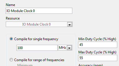
- I noticed that, regardless of the value I put in "Compile single frequency", timed loops using this clock works at 120 MHz. Should it?
- I want to gain at 10 MHz, no 120 MHz. is there a way to create a clock derived from the sample clock? (Right click on the clock gives me not the option "New FPGA derived Clock")
- In the example of the FIDL, engine of CQI on 5734 SMU - 7962R.lvproj, 'IO Module 0 clock' is configured to be compiled to "100 MHz" instead of 120 MHz. is there a meaning behind this value? (# 1, I understand that the value is ignored)
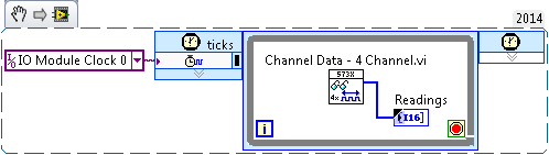
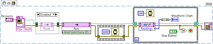
- The code example below, I get "error-61046 occurred to read/write control" unless I have excluded the "Reset" of the VI host node. This problem does not occur if I use on-board 40 MHz clock instead of the clock of Module e/s 0, (although I'd get glitched data). Am I wrong configured something?
- In my current, more complex program, I get the same error even with disabled node, if I stop and restart the host VI - but the next attempt would succeed.
- I have attached the sample file project, the screw and bitfile, where they are useful.
Hi FKSH,
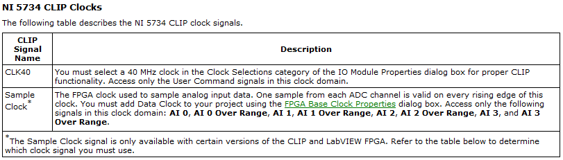
You are right that you must Access your e/s on the 5734 NOR in the area of sample clock:
(this information is by using LabVIEW for the CLIP of 5734 OR)
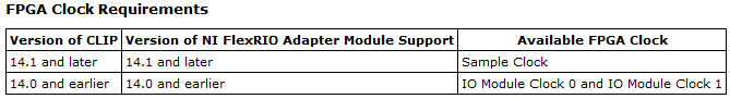
It is a clock Module e/s 0 or sample clock based on your version of the FlexRIO driver you have installed. Based on your statements, looks that you use LabVIEW 2014, so be sure to have FlexRIO 14.0 or FlexRIO installed 14.1. If you have FlexRIO 14.0 or earlier, the sample clock will be IO Module clock 0. If you have FlexRIO 14.1 or later, it will be the sample clock:
(also of the documentation NOR 5734 CLIP in help)
The only support for sampling rate is 120 MHz, unless you use an external clock CLK in and it must be between 50 and 120 MHz (see page 9 of the Manual). If you wish to purchase to 10 MHz, the best thing to do would be to sample the e/s to 120 MHz and then decimate the data by a factor of 12 (keep all 12 data points only and throw out the rest).
Regarding the FIDL, I'm guessing that you're referring to the configuration in the properties of the clock:
This configuration is not actually change the frequency of the clock. The compiler uses this value so that the logic can operate at the specified frequency, but the real clock is provided elsewhere (in this case, the FAM).
Finally, I saw error-61046 occurs more often because of the configuration of the internal clock. Make sure you use the clock on the right as the only cycle timed loop source as I mentioned above. In general, I do not recommend write directly on a 120 MHz indicator, as there are a lot of other logic that needs to be done in order to update the indicator. The data are sent to a domain different clock under the hood, so you can actually update the data and I suspect that there are some conflicts with the clocks. You also lose data as the host won't be able to read all the data before it gets crushed. Instead, I would use DMA FIFOs if you need all the data you acquire or to send the data to a different loop which will be responsible for the update of the indicator in a slower clock domain.
In general, I recommend always that the start-up of the examples in the Finder as a good place to check if the equipment works properly and as a reference for the correct configuration. Once you compile the code, you should be able to run it natively to acquire some data. "" "These examples will be under input and output hardware" FlexRIO "Modules e/s ' NI 573 X ' NI 5734.
Best regards
-
What is the last reading of samples of N in the DAQ assistant
I put samples of N read/output (say N = 10) at certain rate (1 Hz). I wired the output of a number of the indicator. I see not the indicator number change until the operation of 10 data collection stops. What is the final value of my meter number? The last reading or the average of the ten readings?
Thank you
If you did something stupid like data wire dynamic digital indicator, so I have no idea. It is certainly not the average. You need explicitly run the statistical function to get the average. Dynamic data should be avoided if you don't understand what is really done with it. If you buy 10 samples, the data type must be a 1 d table and it would be imposible to wire a pointer to it.
-
determination of the sampling rate and the frequency waveform data record
Hello
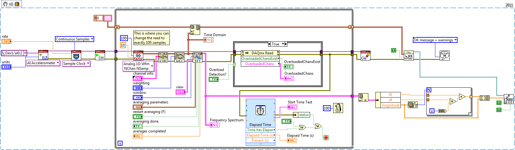
I write a simple program that collect data from a triaxial accelerometer input, convert it to a frequency spectrum, and then save the time domain and the frequency of the waveforms in an external file separated. I don't understand how to set the sampling frequency, however. On the DAQ Assistant, I updated the acquisition mode "Samples continues" and read samples is 2 k, which corresponds to the total number of data points that are collected. How can I program sampling for awhile, it 30 seconds, for example? Wouldn't be better to set up a trigger, as it will continue to collect data up to what I told it to stop?
I also want to save waveform data in a separate file that can be easily seen by other computers that have not installed Labview. I have currently the program put in place to convert a text string of the waveform of the time domain and then save it in a text file or a spreadsheet. It works fine, but I would also like to record the frequency wave, which is a different type of data. How can I do this or is there a better way?
My program is attached. Thanks for your help!
Here's how you can use the shift register to build the table, and also where you can choose to play exactly 100 samples per while the loop iteration.
Brian
-
Create a data streaming from C++ stream and read it in LabView
Hi all.
I'm working on a project that is to connect to a tracker of movement and reading data of position and orientation of this in real time. The code to get the data is in c ++, so I decided that the best way to do it would be to create a c++ DLL that contains all the functions necessary to first connect to the device and it reads the data and use the node to call a library function to power the Labview data.
I have a problem, because, ideally, I would like a continuous flow of data from the code c ++ in Labview, and I don't know how to do this. Put the node function of library call for a while loop seems like an obvious solution, but if I do it this way I'd have to reconnect to the device whenever I get the data, which is quite a bit too slow.
So my question is, if I created c ++ function that creates a data stream, could I read that in Labview without continually having to call a function? I would rather have only to call a function once, and then read the data stream until a stop command is given.
I'm using Labview 2010, version 10.0.
Apologies if the question is badly worded, thank you very much for your help.
Dave
dr8086 wrote:
This method resembles an excellent suggestion, but I have a few questions where I don't think I understood fully.
I understand the basic principle is to use a call library function node to access a DLL that creates an instance of the device object and passes a pointer too in labview. Then a separate call library function node would pass this pointer to another DLL that could access the device object, update and read the data. This part could be in a while loop, then continue on reading the data until a stop command is given.
That's all. I'm including some skeleton for example code. I am also including the code because I don't know how you experience multi threading so I show how you can use critical sections to avoid interactions between threads so that they do not lead to questions.
// exported function to access the devices
extern "C"  __declspec(dllexport) int __stdcall init(uintptr_t *ptrOut)
{
    *ptrOut= (uintptr_t)new CDevice();
    return 0;
}

extern "C"  __declspec(dllexport) int __stdcall get_data(uintptr_t ptr, double vals[], int size)
{
    return ((CDevice*)ptr)->get_data(vals, size);
}

extern "C"  __declspec(dllexport) int __stdcall close(uintptr_t ptr, double last_vals[], int size)
{
    int r= ((CDevice*)ptr)->close();
    ((CDevice*)ptr)->get_data(last_vals, size);
    delete (CDevice*)ptr;
    return r;
}

// h file
// Represents a device
class CDevice
{
public:
    virtual ~CDevice();
    int init();
    int get_data(double vals[], int size);
    int close();

    // only called by new thread
    int ThreadProc();

private:
    CRITICAL_SECTION    rBufferSafe;    // Needed for thread saftey
    vhtTrackerEmulator *tracker;
    HANDLE              hThread;
    double              buffer[500];
    int                 buffer_used;
    bool                done;       // this HAS to be protected by critical section since 2 threads access it. Use a get/set method with critical sections inside
}

//cpp file

DWORD WINAPI DeviceProc(LPVOID lpParam)
{
    ((CDevice*)lpParam)->ThreadProc();      // Call the function to do the work
    return 0;
}

CDevice::~CDevice()
{
    DeleteCriticalSection(&rBufferSafe);
}

int CDevice::init()
{
    tracker = new vhtTrackerEmulator();
    InitializeCriticalSection(&rBufferSafe);
    buffer_used= 0;
    done= false;
    hThread = CreateThread(NULL, 0, DeviceProc, this, 0, NULL); // this thread will now be saving data to an internal buffer
    return 0;
}

int CDevice::get_data(double vals[], int size)
{
    EnterCriticalSection(&rBufferSafe);
    if (vals)   // provides a way to get the current used buffer size
    {
        memcpy(vals, buffer, min(size, buffer_used));
        int len= min(size, buffer_used);
        buffer_used= 0;                 // Whatever wasn't read is erased
    } else  // just return the buffer size
        int len= buffer_used;
    LeaveCriticalSection(&rBufferSafe);
    return len;
}

int CDevice::close()
{
    done= true;
    WaitForSingleObject(hThread, INFINITE); // handle timeouts etc.
    delete tracker;
    tracker= NULL;
    return 0;
}

int CDevice::ThreadProc()
{
    while (!bdone)
    {
        tracker->update();
        EnterCriticalSection(&rBufferSafe);
        if (buffer_used<500)
            buffer[buffer_used++]= tracker->getRawData(0);
        LeaveCriticalSection(&rBufferSafe);
        Sleep(100);
    }
    return 0;
}
dr8086 wrote:
My main concern is that the object can get out of memory or be deallocated since it would not take place to any namespace or whatever it is.
As you create the object with the new, the object expire not until the dll is unloaded or the process (LabVIEW) closes. If the object will remain valid between condition LabVIEW dll calls not a not unload the dll (who does if the screws are closed). When that happens, I don't know exactly what happens to the active objects (that is, if you forgot to call close), I guess the system recovers the memory, but the device could still be opened.
What to do to make sure that everything is closed when the dll before I could call unloads close and remove the object is whenever I create a new object in the dll that I add to a list when the dll is unloaded, if the object is still on the list, that I'm deleting it.
dr8086 wrote:
I also have a more general question of programming on the purpose of the buffer. The buffer would essentially be a large table of position values, which are stored until they can be read in the rest of the VI?
Yes, see the code example.
However, according to the frequency with which you need to collect data from the device you have this buffer at all. That is, if take you a sample on every 100ms, then you can remove all threads and buffer related functions and instead to read data from the read feature itself like this:
double CDevice::get_data()
{
    tracker->update();
    return tracker->getRawData(0);
}
Because you need only a buffer and a separate if thread you collect data at a high frequency and you can not lose any data.
Matt
-
How can I set up a digital input task to read continuous samples?
I am trying to create an exclusively digital task that will make digital readings at a rate timed by the material using a PCIe-6509. However, when I try to put the task timing as follows (which works on a PCIe-6509), I get the following error:
Requested value is not supported for this property value. The value of the property may be invalid because it is in conflict with another property.
Property: NationalInstruments.DAQmx.Timing.SampleTimingType
Required value: NationalInstruments.DAQmx.SampleTimingType.SampleClock
Possible values: NationalInstruments.DAQmx.SampleTimingType.OnDemand, NationalInstruments.DAQmx.SampleTimingType.ChangeDetection
Task name: DigitalInputTask
State code:-200077
The relevant parts of my code are:
public class DigitalInputReader: IDisposable
{
public DigitalInputReader()
{
dataReadyHandler = new System.AsyncCallback (DataReadyEventHandler);daqmxTask = new DigitalInputTask();
daqmxTask.Configure (Globals.NI);daqmxTask.Control (TaskAction.Verify);
daqmxTask.Control (TaskAction.Commit);daqmxReader = new DigitalMultiChannelReader (daqmxTask.Stream);
}public class DigitalInputTask: task
{public DigitalInputTask(): {base ("DigitalInputTask")}
public virtual void Configure (NiConfiguration niConfig)
{
<= niconfig.digitalinputs.count="" -="" 1;="">
{
String physicalChannelName = niConfig.Device + "/ port" + niConfig.DigitalInputs [i]. Port.ToString () + "/ line" + niConfig.DigitalInputs [i]. Channel.ToString ();
String nameToAssignToChannel = niConfig.DigitalInputs [i]. Name;DIChannel ch is this. DIChannels.CreateChannel (physicalChannelName, nameToAssignToChannel, ChannelLineGrouping.OneChannelForEachLine);
c. InvertLines = niConfig.DigitalInputs [i]. InvertLines;
}
var signalSource = "";
This. Timing.ConfigureSampleClock (signalSource, Globals.MachineSettings.SampleRate, SampleClockActiveEdge.Rising, SampleQuantityMode.ContinuousSamples);// Globals.MachineSettings.SamplesPerChannel);
}
}The last call to Task.Timing.ConfigureSampleClock, it's which throw errors.
Of the options available, or SampleTimingType.OnDemand or NationalInstruments.DAQmx.SampleTimingType.ChangeDetection provide the same precisely timed calls that I am familiar with the analog input interruptions.
How is it possible in a digital task? I mean, it seems that I could set up another task to do call by material for the production of a clock signal and use the ChangeDetection synchronization mode, but this seems a bit complicated for what should be easy to do. What Miss me?
Update: I thought about it. You cannot call ConfigureSampleClock when the digital input card is a device of 650 x, because these devices have any automated examples of clock. They are configured to run in mode default finite samples. You must make all sample synchronizing with these devices in the software.
Be cautious, however, because the .NET timers ensure they put any faster than their scheduled interval. In practice, they are usually 5 to 10 ms slow by tick. This means that if you want to read samples every 100 ms by sample clock, you'd end up reading all 108 ms samples. All counters based on the elapsed time and number of samples would be away after a few seconds of it.
Instead, you must do one of four things: write a doggone driver that runs in ring 0 and interfaces with the PCIe card in the required interval (i.e. on NC, not you, in practice), tolerate the inclination of the clock, use a multimedia timer as an interruption audio or video that is more likely to respond to the correct interval, or , my solution, an accurate clock allows you to set the interval of the timer. I wrote the following code to the timer:
var CorrectiveStopwatch = new System.Diagnostics.Stopwatch();

var CorrectedTimer = new System.Timers.Timer()

{
Interval = targetInterval,
AutoReset = true,
};
CorrectedTimer.Elapsed += (o, e) =>
{
var actualMilliseconds =;Adjust the next tick so that it's accurate
EG: Stopwatch says we're at 2015 ms, we should be at 2000 ms
2000 + 100 - 2015 = 85 and should trigger at the right time
var StopwatchCorrectedElapsedMilliseconds = newInterval +.
targetInterval-
CorrectiveStopwatch.ElapsedMilliseconds;If we're over 1 target interval too slow, trigger ASAP!
<=>
{
NvelIntervalle = 1;
}CorrectedTimer.Interval = NvelIntervalle;
StopwatchCorrectedElapsedMilliseconds += targetInterval;
};I hope this helps someone.
-
Config problem and reading of AI
Hello
I have a problem when I use have config and read the structure.
I use Labview new v12.0 and chassis PXI-1042 NI6120 daq card.
If I use NI MAX, I can measure approximately 1 V (which is the minimum value for the sensor) or I can measure 1 V using the voltmeter.
(@ OR MAX, I have set up for voltage analog - NI 6120 - ai0 - 0/5V DC - 20 kHz sampling frequency and number of samples of 4 kHz)
When I use have config and read the structure, I can't measure 1V! Channel ai0 value is 0 a little.
Config and read the ai0 channel structure is attached.
You have an idea what the problem is when I use config and read the structure.
Best regards
Serdar
Two thoughts:
1 looks like to your acquisition is set to finished samples, then you're exciting the sensor before running the code? Or have you tried to change continuously, so you can change the voltage of the sensor the code runs?
2. you mention DC in your configuration of MAX, but your coupling in your "10045" code means coupling AC. Do you intend to use the current alternative or continuous? If you want DC, your value of coupling must be 10050 (or you need to create a constant off the coast of the entrance so that you get the enum rather than use a digital).
Hope that helps!
-Ryan_S
-
complete the loop and get data
I need to acquire the acquisition values of data every x seconds. Waiting in the loop of data acquisition is defined so that the next N samples are acquired after x seconds. Pressing stop the loop of consumer DAQ stops after the sec x which is connected to the wait function.
1. how to stop the inner loop immediately when you press a stop?
I also write acquired samples after doing some calculations on the samples.
1. plan of sample of the queue to file consumer loop. Is there any other recommendations such as drop loop is not without samples? How many data can an expectation of the queue?
Thank you.
sonotk,
You've missed the point. Rather than having a 5000 milliseconds of wait, use an expectation of 100 ms and count the number of times that you have been waiting for 100 ms. When the count reaches 50, sample and start the count again.
The counter is just in the shift register containing an integer. Inside the while loop you have a box structure. Test the shift count register to see if it is 50. If set to True, use the real case of the structure of the case. Inside, it's all in your loop except waiting and the logic of the judgment. In the case of false, you add 1 to the shift register and wait 100 ms.
Looking at your picture code once again, it seems that the shift with TempData and VoltData regsiters are not necessary because you never use the data previous iteration on the left side.
Ranjeet,
Make a simple VI with two loops and some expectations. Run with execution highlighting market to see what is happening. It is a good learning tool.
Lynn
-
. VI filtering IIR and response: response of Butterworth filter size depends on sampling rate - why?
Hi people,
I'm not an expert in the design of the filter, only a person in applying them, so please can someone help me with an explanation?
I need to filter signals very infrequent using a buttherwoth filter 2. or 3. order of the bandpass 0.1 to 10 Hz.
Very relevant amplitudes are BELOW 1 Hz, often less than 0.5 Hz, but there is as well the amplitudes beyond 5 Hz to observe.
It's fixed and prescribed for the application.
However, the sampling rate of the measuring system is not prescribed. It may be between say between 30 and 2000 Hz. Depends on the question of whether the same set of data is used for analysis of the higher up to 1000 Hz frequencies on the same measure or this is not done by the user and he chooses a lower sampling rate to reduce the size of files, especially when measuring for longer periods of several weeks.
To compare the response amplitude of 2nd and 3rd order filter, I used the example of IIR filtering .vi and response:
I was very surprised when I found that the response of greatness is considerably influenced by the SAMPLING RATE I say the signal generator in this example vi.
Can you please tell me why - and especially why the filter of order 3 will be worse for the parts of low frequency below 1 Hz signal. Told me of people experienced with filters that the 3rd oder will less distort the amplitudes which does nothing for my the frequencies below 1 Hz.
In the attached png you see 4 screenshots for 2 or 3 command and sampling rate of 300 or 1000 Hz to show you the answers of variable magnitude without opening labview.
THANK YOU very much for your ANSWERS!
Chris
Hello Cameron and thanks for my lenses of compensation.
I can now proudly present the solution of my problem.
It seems to be purely a problem of the visualistion information filters through the cluster of the scale.
After looking in the front panel of the IIR, I suddenly noticed that the "df" of the pole size is changing with the Fs of the input signal.
For a Fs to 30 Hz, the "df" is 0.03 Hz so you see the curve of the filter with more points, see png.
For a Fs 300 Hz "df" is 0.3 Hz, so the curve is larger with only 3 points between 0 and 1 Hz.
For a 1 kHz Fs the df is 0,976 Hz, so there is no point in the graph between 0 and 1 Hz.
It's strange that for constant Fs, df of this cluster NOT reduced with the increase in the number of samples, as it does in an FFT.
However, I hope now the filter used now for the curves obtained with the proposed Lynn way and the response of greatness from the filter information fit together.
Thank you for your support.
Merry Christmas and a happy new year to all.
Chris
-
What is the relationship with the sampling frequency and number of samples per channel?
In my world, if I wanted to taste 10 seconds 10 Hz (100 s/ch), specify a rate of 10 and a number of samples of 100. This would take 10 seconds to return data. The task does not appear to behave this way. No matter what rate and the number of samples, I chose, I spammed with data at 1 Hz or more.
What I am doing wrong?
This problem is resolved by making a request for telephone assistance. It turns out that the minimum sampling frequency of the NI 9239 is 14xx s/s. I don't know why there is a minimum sampling frequency, but now I have to go to the next question discussed at this link:
-
channel and sampling rate is not updated until the next cycle
Hi all
I'm new to LabVIEW and I wrote the code for the measurement of temperature using the cDAQ-9178 or NI 9214. Could someone please look at my code and help me understand why... my names channel to sample and rate update, until the next time I run my program.
For example: if I enter the name of the channel "ONE" and "10" sampling frequency... and draw my program will be executed using previous information entered by the user. If I press the race a second time, then it will use the '10' sample rate and channel "ONE". Everyone can't see what I did wrong? I know that my code is absent, but she does everything that I need, except for the update.
I really want to use a structure of the event, but failed miserably in my attempts. Thank you
Stream. Updates the values in your Subvi are run in parallel to the Structures of your event. The simple solution is to simply put your update of the values inside the event. In this way the controls are not read until you actually press the next button.
Maybe you are looking for
-
31 Firefox on Linux Mint 13 suddenly stopped to save tabs or warning on close
Have used this system for about a year. Update Firefox once or two. Always worked very well. In the last months I kept several tabs open that I wanted to keep but are not currently working with. FF has always presented the 'Save and exit' box, and al
-
my laptop turns off after 5 or 10 minutes, it's hot and I can't hear the fan, the fan still work? If the fan is not working properly, how to fix?
-
my pc had a new hard drive and came back without windows vista. I have no backup discs. Help
the hard drive on my computer packed. I sent it for repairs under warranty and it was returned under Windows Vista. How can I get it back? THX
-
After the installation of Windows 8, I lost my photos
After the installation of Windows 8, I lost my pictures and can not find them
-
We are a non-profit 501 c 3 that is the subscription price for us?
We are a non-profit 501 c 3 that is the subscription price for us?