Modbus master
Hello
I have a question about MODBUS/TCP.
I have to write BITS of a register of exploitation. Unfortunally, operating records accept unsigned values (numbers).
That's why I need to convert my binary value (for example 101000 > 5).
But now I want to write a single bit value, without touching the other bit values. I think I need some sort of MASK for this LabVIEW say the individual bits, I want to write.
Example as an attachment.
Does anyone have experience with a MASK in MODBUS/TCP in LabVIEW?
I found on the internet of things on "Holding Register Bit mask written" and that 22 function Code must be used, but I don't know how this can be used in LabVIEW.
Info on a mask in MODBUS (top 3)
http://www.Micronor.com/products/files/AN112/AN112_NIModbusTutorial.PDF
How a mask must be used in the writing of a registry (section 4.3.4 mask write register (CF 22))
http://www.rtaautomation.com/ModbusTCP/
Thank you
Arjen
Read first to keep record and then together your forest write it later. Its same only
Tags: NI Software
Similar Questions
-
Interface MODBUS master/slave... need DSC & OPC?
I read up on top of the DSC & OPC modules looking at reasons why I would or would not need these modules for my particular application.
I have a custom designed PLC I need to communicate with. We look at the advantages/disadvantages with regard to the use of MODBUS ethernet communication to send control commands & reception around a number of 100 channels input data (1 to 2 times per second). LabVIEW on Windows system is the master device and the seat PLC as the slave device. Will we have the DSC or OPC modules? We seek to create our custom MODBUS code. Is here, that make the DSC & OPC modules really do? More of a plug-and-play option for customers do not have to develop a custom code? Develop a code custom this broad? It seems that I could with just the drivers MODBUS provided through LV... but would like to hear your comments on that.
Also, the MODBUS ethernet is quite easy to configure on the deployed applications (desktop / laptop)? Currently, we use an IO CAN for connection & this works pretty well and is easy to install and deploy... but is a bit expensive.
Thank you
Hello
The main advantage of the DSC module is that it allows you to use variables shared in the form of tags to connect on multiple protocols (such as MODBUS or OPC) industry, which eliminates a lot of hassle with the side of things communication. In addition, it allows the log all your variables to a relational database, as well as alarms and events with a minimum of difficulty. I won't get in the list of full features here, but if you're interested, you can learn more about DSC Module information page.
For your application, it seems that your PLC will make communication MODBUS Ethernet, OR OPC servers shouldn't be necessary unless you really want to publish data PLC to OPC for some reason any (without programming). In addition, if you want to use OR OPC servers, you probably want to make sure that proper operation with your PLC. There is a hardware compatibility page that lists compatible devices.
The main advantage of using DSC on the MODBUS library is ease of use and deployment. Since all your i/o MODBUS is on your shared variables, your application data sources are all managed by the LabVIEW project and can be changed centrally.
For a quick - and dirty preview, there is a demo on the latest features DSC and demos (link to the demo) page. This particular demonstration shows how to read and write specific addresses on MODBUS Ethenet without wiring from a single piece of LabVIEW code.
If you are looking for a cheaper alternative, the MODBUS library is definitely worth looking into. My recommendation is to try the DSC Module and the MODBUS library and see which suits you best.
Good luck!
-
Hello Forums or
This is my first post on this forum and I've been using labview for about 8 months now
I have a problem about writing data in the modbus registers through a server of e/s defined as a slave modbus for my hardware 9074. Once I finished the project of construction and deployment of the variables and by following the instructions here , he reports no results but a row of zeros. I have the DSM nor opened and configuration modbus master to see whether the data is actually read or written on the respective sides that give the same line of zeros so. What I am actually trying to write is a single-precision floating data table. The registers are structured F40000-F46534 runs from 10 items or have them for range AF40001L1-AF46534L1 of the AF40001L10 point where it's an array of length 10. (Referenced beaches here)
I know 1 thing for you, the modbus connection works and is ready for data requests, I tested cela NI DSM and set manually the data for and received my master.
System and project specifications
Windows 7 operating system
LabVIEW edition development system complete 2011
No module Labview DSC, but I use the real time such referenced by one of the documents
This project is an application in real time with fpga mode (and not scan interface)
The master and the slave are the same network and subnet
Connection Modbus type: TCP
9074 compact slots rio 8
9234 module x 3
module 9221 x 1
9472 module x 1
Engine service Variable shared running on windows os and rtos system
Used this guide to learn more about the Protocol modbus, as I have searched all over the internet to learn more about modbus
I already have software Modbus IO Server installed on the crio thanks to max or 1.8 for NI RIO 4.0 version
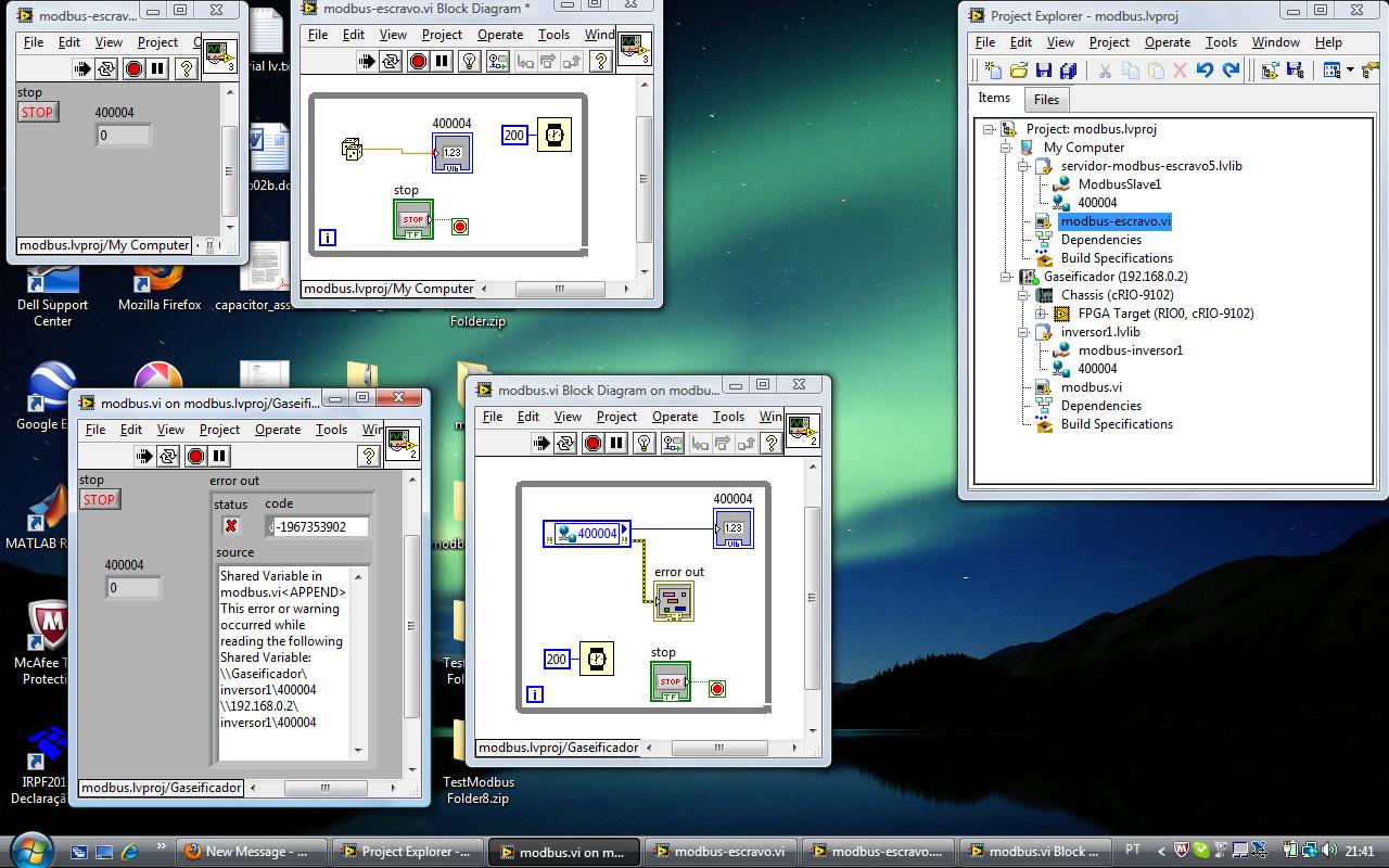
file attachment (s)
Image of software specifications Crio
Image of data written in scheme-block rt variable
Short version of the problem: why is the e/s no variable writes in with the converted correctly data?
Okay, Yes, it's that I was the one proposed. Regarding the news of the error, if you look at the bottom of your image to DSM, you see a little commfail and an error code, but it seems that those are OK.
The only thing I can think is that DSM (or another function) is written for a range of values that includes 400004. I suggest you to put into service 4-going to a range of 3. 3 s are entered only (perspective control), then you can be sure that the master is not trampling on the data. Once you have checked that, look at DSM and any other code running to make sure q EU not accidentally write 0s to the same reg.
-
Analog value read with DSC Module Modbus
Hi, I have a Delta PLC with an AD converter module. I use the four analog channels and in one of them, I have a thermocouple which displays temperature data on a microprocessor thermocouple meter. However, I want to display the data in Labview. The controller communicates with labview through the DSC Module of labview with success, but I am not able to read the data. Looking forward to your help.
Found the solution. addressing to the modbus master was different for this model of plc, so I looked up the address for delta plc Modbus and the analog read list has been a success on labview.
-
Cannot write negative values on server modbus on cRIO 9068
Hello everyone,
I'm moving a project from a platform of 9114 cRIO a cRIO9068, the reason for a difference of heavy in terms of power CPU, memory, performance FPGA etc...
Real time I deploy a modbus TCP server, and I publish just I16 data.
The problem comes when the program tries to write a negative value to a binded on modbus variable. This variable is in the same format (I16), the program could write negative values, between 0 and -32768, but whenever the modbus force set to zero.
I tested the modbus also with the 'system of distributed OR 2014 Manager' but always impossible to write negative values on I16, but I can if I consider the data as I32!
(see files)
Furthermore, I deployed a modbus server on my PC and in this case, everything is fine.
More information:
I work with labView 14.0f1.
The cRIO are installed 'Labview RealTIme 14.0.0' and 'server Modbus I/O 14.0.0.
I tested the feature on three different cRIO 9068 with the same result.
I think it's something wrong with cRIO 9068, can anyone help me?
Thank you
MZ
Hi, Marcello,.
I was able to reproduce the problem cRIO 9068 and it look like a CAR (corrective action request). I've opened a request for Corrective Action (AUTO ID 511039) to report the issue OR R & D.
Have you tried to implement MODBUS slave on ana MODBUS master PC on cRIO? I tried and it works even with I16 data types.
I hope this will help you.
Kind regards.
Claudio Cupini
OR ITALY
Technical support
-
writing multiple modbus registers
Hello
I am communicating to my labview program controller using modbus RTU and the controller has 16 bits in modbus registers.
To send the float as '1.23' values, I write two registers to store the hex value that number in comma floating 32 bits.
I use the modbus driver provided to this end by labview and use labview 8.2.1
I have the following doubts in this regard.
- The "Modbus master series query. VI"has the command Modbus that records an entry which I use to set the registry values in the controller unit modbus. To send the above, mentioned in floating-point registers 501 and 502 (contains the full value of the PID parameters), use the same vi, whose value should be registered first... is the high or low, to be written to 501 and 502.
- The function code to write to multiple records in the modbus driver is 16. But my document that is specific to the Controller explained in the section "writing to multiple records" with the code of function like 10. And I see that feature codes 'writing in the single register' as well as the driver for modbus producing the same type of message frame as discussed in the document. But I see no similarity in the function "write multiple registers" in the document and the modbus labview driver.
- "Even if I write records 501 and 502 one after another will use"write in the single register"function code when these registries implement floating-point single using 2 registers ' 16 - bit '. If this method is possible, then I will come and do it the same way I did it for the entry in the single register. While writing data in records one after the other with a gap between the two as small as 4 ms scriptures do good?
I suspect a confusion between 16 decimal and hexadecimal 10

Two successive registry entries are not equivalent to a double entry: during the period between the two scripts your controller will be loaded with a false parameter. It is perhaps not necessarily a source of problems. It depends on your application. Writing the MSB should first reduce the problem.
The order of Hi-Lo is dependent on the machine control. Some use the Big Endian, other Little Endian. But this choice should assign unique register values (U16) as well.
If it is not documented, you should read the records and see if the result is logical. If this is not the case, invert the byte order and verify that the problem is resolved. Good luck

Also, I assume that you know how to use the conversion feature to convert a single (32-bit float) 2 U16?
-
cRIO, modbus, DECS and Micom relay
Hello
I am keen to talk to the DECS 200 and 300 DECS and also devices Micom relay. I need Modbus to communicate with them. I understand that I can use a cRIO as a slave, but is it possible to use a cRIO as a modbus master so I can request data from devices?
Thanks in advance for answers
Hi JChec,
In fact, you can configure the server of Modubus of e/s on a cRIO as a master Modbus or Modbus slave. I enclose a window here where you can see how these options are selected.
-
Debugging of Modbus slave on tatger in real time
Hello!
I have problems when you debug an application that contains a slave modbus on a real-time target.
The connection is lost when I run the program.
Change the port from 502 (default value) to other values seems to solve the problem.
LabVIEW uses the same port to connect to the target RT?
THA same problem notified here, but I received no response:
http://forums.NI.com/T5/LabVIEW/NI-Modbus-TCP-slave-on-LabVIEW-RT/m-p/1565842#M575497
Kind regards
Marco
p.s., We use the libray modbus labview (http://zone.ni.com/devzone/cda/epd/p/id/4756)
Hi Marco,.
as far as I know the port 502 is used only by the Modbus Slave Servers (Ethernet) i/o to connect with e/s Modbus master servers so you should not see any conflict using this port.
(no other LabVIEW service is using this port).
You can check if you have deployed Modbus Slave (Ethernet) i/o duplicate servers. Modbus Slave (Ethernet) i/o duplicate servers cause errors when these I/O servers listen on port 502.
Hope this helps
Clara
-
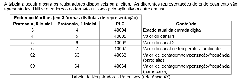
MODBUS RTU - problem reading Holding - myPCLab Novus records
Hello
I've tried for a few days to read the logs at Novus myPCLab (it uses the Modbus RTU Protocol). I used the DSC module both Modbus Library without success (it seems to connect properly but cannot read).
I need to read the given current.
Does anyone have an idea on what am I hurt?
Here's my vi and modbus address.
Through the DSC
I used the address PLC to 'HR Inicial' and 1 'St number.
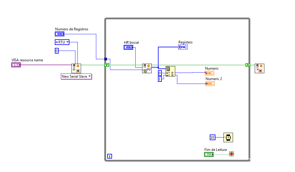
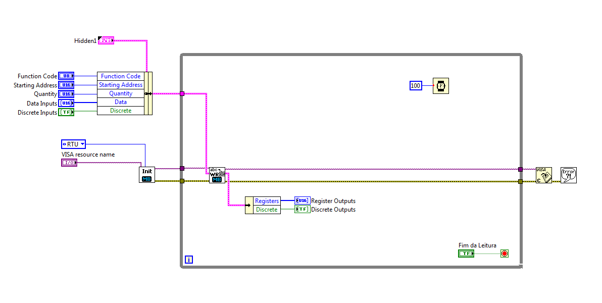
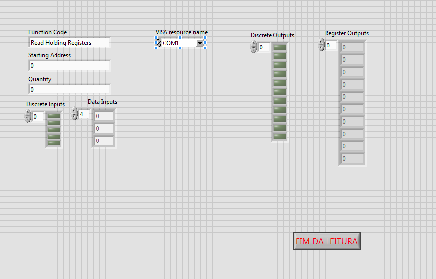
Through the library
I used the PLC address in "start address".
You have created a connection that is configured to use a "unit ID" 0. Slave never devices typically use a device number 0 which is considered to be a broadcast address.
Check the address of the slave of your device. So make sure that you use this number.
I guess that you communicate with a device that behaves like a slave. If so, you must create a Modbus master in your code. With the new modbus communication protocol Subvi, you created a slave. A slave cannot talk to another slave.
Similarly, in your second picture when you use the older Modbus Library, you not connected any constant to the top of the SubVI WriteRead that defines the parameters of series of devices such as RTU and address of the slave, so she takes by default to 0. Once again, a broadcast address.
-
Test serial modbus communication
Hello
I would like to test server-serial communication modbus master running on the CRIO (9012) and the serial modbus slave server communication.
Issues related to the:
Is this possible? Two VI run simultaneously? If so, what am I doing wrong
The CRIO is connected by ethernet and series with PC.
Best regards
-
Modbus/TCP connection to the controller of power Eurotherm EPack
There are examples of how to connect to a power controller Eurotherm EPack a modbus/TCP connection?
I downloaded the Modbus LabVIEW ni_lib_modbus_library library - 1.1.3.32.vip and installed using VIPM.
However, I am not familiar with the Protocol modbus and terminology such as coils, keeping records.
I can't even properly run examples for Modbus master and slave to this library :-(
Most important for me now is just to read the value of the artwork process.
"ITools" Eurotherm controller software provides information about something I think are an address of memory the value of process I want to read.
However, I have no idea how to set the various parameters to get successfully connect and read the value of the process.
Trying to solve my problem, I managed to have basic communication and engineering data conversion.
Now I can read values of process as the power line frequency, voltage and others.
Once you know, it's very simple (once you have the modbus library)

Some things that remain unclear:
-What values are 32-bit and 16-bit?
-is the method of addressing identical for all parameters?
-is it the same for reading and writing?
I would like to be able to write the target value, for example.
I'll contact the seller for these outstanding issues. The manual is not really clear (at least not for me). He mentions that some values may be treated differenly (they 16bits, but globally, so 5001 with a scale factor of 100 means actually 50.01 for example).
See the attachment for reading cover base.
-
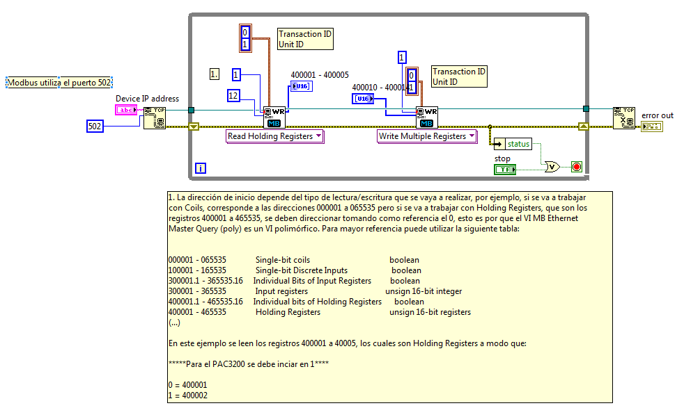
Modbus - Labview no me detecta mi componente Québec uso ip
The mando a cordial greeting. The problem that I have, that're estoy utilizando UN pac3200 of siemens that're fr if a voltimetro el cual por medio del porotocolo modbus me mando los datos has the ethernet medio por computadora. the situation that're cuando el Server en labview genero y creo el modbus master genero el vi y me marca cual un error en el me as soon as no ha first una respuesta por parte del helped modbus, which in this case is el pac3200 viene. Check that the property is intellectual led device fuese correcta por medio compando 'ping' in windows ' CMD' el communication between the computadora y y el pac3200 TR're correcta, el problema are corpos el programa labview don't me lo reconoce. Another situation that no he could confirm if're los datos Québec me mando son validos. Los datos that manda me el pac3200 son of tipo life (32 bit), abia read that this type of data packages don't hay as descomponerlos en 16-bit packages, convertirlo a binario y posteriormente, pero concatenarlos no to esto sea cierto cuan. If alguien sabe o ha tenido este porblema, is the agradeceria mucho knew ayuda. Saludos
Saludos
Los datos than recibes para el caso del CAP deben ser los procedures in los St Holding y estan in U16 esos los you must convert a reales este VI use the libreria NIMODBUS121
-
Send data and receive commands by VBAI of VB or c#
Hi, anyone has examples on how to send VBAI data and receive commands by VBAI of VB or c#.
I intend to hand over command to the VBAI on and outside, get the image and stop start.
For the data to be send are the result of the calculation of the calculator function. The data send each time to do the math.
I have search the forum and I know that this can be done by using labVIEW. However, due to the requirement of the question, I can't do it using labVIEW.
Thank you.
Yen
Hi Yen,
"" "You're almost there. '" Here are the steps for this example works.
Once you open the inspection in Vision Builder, go to tools > Communication Device Manager...
You must create a Modbus master device, which corresponds to your communication of VB with Vision Builder application.
Click on the new device. Give it a name, say "VB program".
Select Modbus TCP for the Protocol.
Click OK.
On the Modbus server line, click Start Server. This starts the background task which is listening on port 502 for incoming Modbus messages.
Click OK to exit the dialog box.
Now, a couple of things to understand about Modbus: the Protocol specifies how a device Modbus master can read and write registers located on a slave device. Vision Builder has 4 64 k save tables:
-Coils (read/write binary, by the master).
-Tor inputs (binary, not read by the master).
-Entrance to the registers (16 bits, not read by the master).
-Holding Registers (16-bit, read/write by the master).
The tolerances of the inspection reading read minimum and maximum intensity in Modbus 0 x 0 and 0 x 1 operating records.
If you want your VB application to write these values.
Here's the Modbus function codes. You can get the full list by downloading the specification to Modbus.org Modbus.
0 x 01 reading reels
0x02 read discrete inputs
0 x 03 playback record keeping
0x04 read input registers
0x05 write single coil
0 x 06 write single register
0x0F write multiple coils
0x10 write multiple registers
To use your example Modbus program to read and write registers Vision Builder, first enter the IP where Vision Builder is running:
127.0.0.1 (localhost)
For this example, use the function Code 6 to write a single business registration.
The Modbus data must be formatted as follows: the first 2 bytes are the starting address, the following 2 bytes are the value (U16) you want to write to the registry. So to write the value 1 at 0 (corresponding to the intensity of the min), the data value Modbus 00000001. Click on send.
Now, to set the maximum intensity at 50. Set the data to 00010050. Click on send.
Step write data written minimum intensity of step to check the presence of CAP in the Modbus 0 x 0 registry entry and the status of the step in discreet entrance 0 x 0.
To read the intensity Minimum written by VBAI, the value of the function 4 Code (enter reading registry). For the Modbus data, the first 2 bytes represent the address, 2 bytes, the number of registers to read. The value of data Modbus 00000001 to read a single registry entry to address 0. Click on send. The response data can be for example 0x1E, which corresponds to 30 decimal places.
To read the status of the step, set the function Code 2 to read discrete inputs. The value data 00000001, to read the first register of the discreet entry table located at address 0. The response data is 0 or 1 (success or failure).
I hope this helps. Let me know if you need other information. But this should help you get started.
Best regards
-Christophe
-
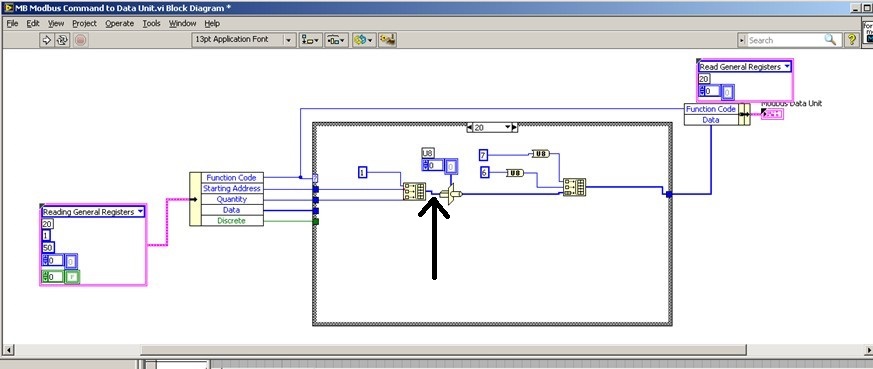
Hi all
We try to add 20 saving file read function code in order to read the brief in bulk from PLC. We used the modbus for Labview library to communicate with the PLC with Modbus TCP/IP, but when I addes the code function 20 to the cluster of the MB Ethernet Master query entry reading registry Palette entry, the program displays an error. I'll be really appreciated if someone could help with this problem!
We hope all have a good weekend.
Best regards
Sophie
Actually... that is a constraint on the second entry to "build the table? ' It is difficult to tell from the image. If so, what is the data type of this cable?
That must be an array of U16s, because the "quantity" and "home address" are U16. However if the value '1' is a larger data type as U32, labview perhaps at upconversion of the whole table that would result in a larger data set than expected and could cause error 2. You can check on this?
-
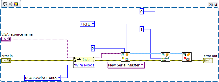
Power Meter Modbus rs485 via 9871
Hello
I'm under Labview 2015
I'm currently trying to connect has the place D Pm820 (meter) NI 9871 module in a crio 9076. The project is supposed to read the performance data in the registers of the meter (current, voltage, etc.) using the port rs485 on the back of the meter.
The pm820 has a pinout for rs485 2-wire with 1 (-) 2 (+) and a 3rd Armor/ground wire. The pm820 meter is a slave device that has several different protocols that it can run on (Modbus RTU/ACII8/7 and JBUS).
The setting of the counter are:
Protocol: Modbus RTU
Address: 1
Baud rate: 9600
Parity: None
I use the module 9871 for device communication for the cRio
I use the power cord that came with the module 9871 RJ50 to db9 and have the pins 4 and 8 rider (TXD + TXD +), and then connected to the (+) 5 and 9 meter jumper pins (-RXD, TXD) - and then wired to the (-) meter and ground on pin 1. I have read, it's how wire you the db9 connection rs485 2-wire.
My first goal is just to get the communication with the power meter so that the value that I see in the registry, it is what I should see.
I started using an example VI for holding registers (master modbus on target RT) reading as labview was pre-constructed and changed it so that its contribution would be to port 1 on the 9871 as created controls for my run configuration. Other I left the rest of the VI that it has been opened.
When I run the VI I see numbers appear in the registry list, but they have nothing to do with the power meter. I unplugged the power meter and still got the same result however if you unplug the cable connection the 9871 1 VI will be a mistake (as expected). I have the feeling that the labview speaks to itself through the 9871, but I'm not sure. I looked at other posts, trying to find a solution and came across a mention of having to set the thread mode, but I can't find a way to do it using the modbus library. However I could not find an example reading VISA registers the using visa I see there is a way to do it.
I enclose a picture of my VI and the front panel to show what I mean.
If I could help either make my VI work or at least get pointed in the right direction that would be great. I'm not against the use of the Visa library either. Also if you have examples or resources that would allow that they would be greatly appreciated
It's just a part of my project but just get work communication is my main priority at the moment.
Thanks in advance,
Mike
Maybe you are looking for
-
Upgrade satellite 1900-102, hard drive
Hello... My laptop is a toshiba satellite 1900-102 with a 20 GB hard drive. I would like to ask if I can upgrade the hard drive with another model and not the classic toshiba MK * 18GAP. Is it OK to use a hard drive from another provider? I want to u
-
Windows XP installation without success
Hello, I am trying to install Windows XP Home Edition on a Compaq Presario V2670CA. The old hard drive broke down and there is no way to recover the data. Slipstreamer tried according to the guide on the top of the page and I've tried all the sata dr
-
HP Pavilion dv6 Notebook: abnormal noise out of the body of the laptop
HP Pavilion dv6 Notebook (bought year 2009 I was working in Qingdao in China as corporate PC) has started making a noise when using, it started about a month there is early December. I tried restarting several times but its abnormal continues and I a
-
How to detect Ctrl + u and open a new window of vi
How to make event, thank you.
-
I forgot the password of the user profile in the Windows XP computer.
Original title: Please HELP me. My roommates decided to change my profile password and not I need my computer and they do not remember the passwor... Can someone halp please? !!!