More and more common digital output on USB-6001 with ULN2003A
I am ordering an engine step by step and the current required on the digital inputs of the stepper driver is close to 11mA (at 5V). My USB-6001 is not capable of producing this high current. I've seen people using the ULN2003A to control relay and it looks like it should work for my application. It will work and then I use the 5V output to go to the ULN2003A because it can produce for a 150mA. To associate the ULN2003A I use the 5V output and put the positive on the COM?
As you drew it should be fine. Do not connect data acquisition + 5 V because the controller inputs are opto-isolated. That circuit is also compatible with the 11 current requirement my mentioned in your first post.
USB-6001 digital lines are software timed so your maximum stage rates will be very high.
Lynn
Tags: NI Hardware
Similar Questions
-
Is it possible to plug a USB to my new iPad Pro, to transfer PDF files and some Jpeg files from the USB key with an adapter of lightning? If there is NO adapter, how can I get these files on the USB key and my iPad pro? I need these PDF files transferred my I touch pro. Any suggestions? Please
Thank you
Mike Tingey
The iPad does not support USB keys. There are some wireless flash drives that can be used, but not the classical records. I suggest you transfer files to a computer and their synchronization then back to the iPad via iTunes.
-
CV 1457RT and VBAI: Double digital output
I have a problem with the CVS 1457RT and the VBAI.
I configured two steps with the VBAI for the CVS.
The first step: I've read about the digital input which should trigger my second step.
the second step: I acquire an image (with an ACE of the Basler) and then I measured 8 distances and count 2 edges. After this, I generate a pulse on the digital output once.
After that I did a VI in LabVIEW that measures the time between the IO.
In this VI and on the module which is connected to the digital output, I see that the putput pulses twice but only a few times.
I guess you get noise on your digital input and trigger twice, so that it works the inspection twice, giving you two pulse output.
You can implement a digital filter, where the value that comes out of the filter does not change until entry remained at the same value for the N samples.
Bruce
-
How to generate a square wave of continuous digital output using USB 6343?
I need to generate a square of 600 kHz from my 6343 wave. The specifications indicate I could use PINS P2.0, but I get an error saying that it is not supported.
Thanks in advance for your help.
Jodi
Dan,
Thank you very much. Counter method worked very well.
Jodi
-
USB 6008 digital output signal
I am VERY new to LabView and have been racking my brain trying to get digital output of my USB-6008. All I want is to be able to get a signal of + 5 V of my digital output when I click on a button. This signal opens a valve on a system I see so when it is pressed, it must stay open until I press the new button. It seems simple enough to me, but I'm not too familiar with LabView. Help, please!
Stripling07
You must first take the LabVIEW tutorials and then look at the links to get started with DAQmx .
The simplest program would be with the DAQ Assistant. Drop it on your schema, and then select digital output > digital line. Select the line when the wizard has completed, click OK. Wire a Boolean value in a table to build and the output of which is connected to the data entry. That's all. You can test the output of MAX (Measurement & Automation Explorer) with the test Panel. Do NOT test with your connected tap. Your valve may require more current that can provide the 6008.

-
Pull-up external USB-6009. digital output (open collector) allows onboard external + 2.5 V output?
Pull-up external USB-6009. digital output (open collector) allows onboard external + 2.5 V output?
Hello
I want to config output digital USB-6009 to + 2.5 V above and 0 V digital output low. I know I can config USB-6009 digital output open collector with resistance to pull-up external, that can be applied with + 2.5 V power source.
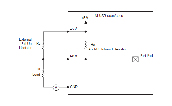
My question is: can I use USB-6009 Board + 2.5 V output as the current source of resistance to pull-up? What resistance is a good number for the resistance to pull-up, if I can use this configuration?
Thank you much for the help.
Cathy
Hi Cathy,.
The digital USB 6008 front-end server looks like this:
So, there is actually an internal pullup to 5V 4.7 kOhm resistance when the device is configured to open collector.
If you want to display 0 to 2.5 V, I would look in a resistance of polarization of 4.7 kOhm between c and ground (according to the rest of your tour).
Best regards
-
Hello
I use the digital output to USB-6343.
Sometimes when I stop writing (clear the task) the rest at high output pin (I see it in the oscilloscope).
Is it possible to set that after earasing task output pin will always be low?
Thank you
Leonid
Thank you
-
Control the Boolean commands and generate a corresponding digital output
Hi all
I'm working on a project of activation of the electrode, here, I thought that how could I order an electrode in a time and generate a digital output of it accordingly. I want to replace it with each electrode with a LED on the front panel and generate a numerical value to each LED on the block diagram.
If it can be divided into two parts
1 control the Boolean outputs
Here, my goal is that if I have 5 leds that are used as a Boolean control, must be ordered so that only one of them lights up at the same time and the rest goes off.
I mean for example if #3 was turned on and that the user pressed the #3 #2 should be turned off and only #2 lights.
2. generate the corresponding numerical value
Depending on the position of the LEDs I want to generate a corresponding numerical value, as previously released 3 coming and exit 2 then comes when the second LED illuminates.I ask all participants to this group to help me with this.
Concerning
Why don't you use the radio button control? You can replace the boxes if you want the buttons.
-
digital output ARM nodes shipped
I MCB2300 and something more nodes digital output provided (LED 0-7). I have consulted for additional i/o elementary to the instructions here:
http://digital.NI.com/public.nsf/allkb/85DDB6218E7CEEBD8625756D007967CE
However, it only provides additional digital input nodes (even if the pins for these nodes are general-purpose digital input or output).
Is there a method to change these digital ouptut nodes?
Thank you
Hello
The generic MCB2300 target requires the following to access the outputs digital EIO:
- Add EIO of digital input of your project (as in your photo)
- Drop the EIO of digital input on your block diagram
- Click with the right button on the EIO node, and then select 'change to write '.
-
Trouble with USB-6501 with Labview 8.6 Pro for Mac OS
Hello
I have a unit USB-6501 I try to use with Labview 8.6 for Mac Pro to processor intel.
I have the driver NOR-DAQmx base 3.2 for Mac installed and when I ran "Isdaq", it detects the device and also warned that the firmware needs to be updated. So, I ran the "FWUpdate" for updating the firmware. I double check the Isdaq and it detects the device as "NI USB-6501:"Dev1"(USB0::0x3923:0x718A:014386 B 0: RAW).
Now, when I run Labview 8.6 and DAQmx Base create channel VI and the port of 'physical' wire to the control, nothing appears in the available device.
Also, when I run the mxbaseconfig program, not the existing basic tasks detect the device.
Could someone please help me get this to work? Basically, I need to read and write slow digital data through USB-6501. But, the Labview does not detect the device.
Thank you
Keong,
I do not know what causes this, but place a task create VI before your code and the wire of the output task to the task of entering the chain and try to run that. Please let me know if it works for you.
-
Initial (and probably more common) question of Dr on SRM and private networks
Hello
Can anyone share best practices on the ground with regard to my question archiecture of network:
According to the guide of the SRM administrator: Mrs. in protected sites and recovery must have access to the same private network (logic).
We will have protected sites and located on the same ground but both recovery are far from each other on separate parts of the campus and there is network connectivity between sites.
What are the different ways we can get two separate sites to share a private network? What is the best practice?
(1) fiber optic cables directly between sites using Layer 2 switches? Any potential problem with switching over a distance?
(2) with Layer 2 VPN MPLS? Enough to handle the traffic scenarios and failover/failback mature?
(3) should work around SRM to allow a routed 3-layer solution?
I'm from VMware
As I said more simple solution is scalable layer 2 making available of VLANS / subnets in two sites in order to avoid the re-ip address of the recovered virtual machine. MPLS and direct DC of interconnection on fiber/xWDM were popular alternatives for the extension of the L2. As with anything there are advantages/disadvantages for things like network and mobile IP service (for example, routing, load balancing, etc.) of persistence or rigidity. The Cisco & VMware following white paper might be of interest that it focuses on a new DCI solution that introduces new options for VM environments. The paper is mainly centered around the Cisco Nexus product range and the ability to now support active/active balancing on various, redundant DC links:
http://www.Cisco.com/en/us/solutions/collateral/ns340/ns517/ns224/ns836/white_paper_c11-557822.PDF
You will notice the support of max distance of 200KM that is referenced in the document comes from the limits of support for the underlying storage replication (200KM for most synchronous suites), but there is also the effect of the reactivity of latency and VMotion application considerations. Site Selector Global (Cisco GSS) can be used for the traffic of a smart-balancing the load on the front-end server application as well as for unloading DNS service, DHCP and other common services - it would be more of a supplement to the core DC interconnect solutions mentioned above and not necessarily an exclusive alternative.
Not sure what you mean by a workaround for Layer 3. SRM has the ability to re - ip of the VM during recovery, allowing you to change all THE info from the network stack inside the VM (network/gateway/dns servers ip/mask) and even generate scripts of ddns, but according to my post previous changing network info is in almost all cases, I worked with a customer "2nd choice".
-
How can I more easily generate a pulse of digital output of finite length?
Hello
I need to open and close the two pneumatic valves using a TTL output (without load current or the output power) using a PCI-6280 or PCI-6601. The valves must open almost simultaneously and closing after different amounts of time elapsed (millisecond level timing, maybe 100 microseconds-level timing at worst). My current plan is as follows:
-Create a task with two digital outputs (type of waveform) and another task with a counter that generates a frequency set by the user (I know I can use the generator frequencies on one of these cards, but I would have preferred a counter - the best selection of frequencies).
-Wire the output of the counter at the entrance to clock two digital outputs.
-Output of the meter is digitally triggered by another digital channel which I use to control if the pulse goes out. Through its counter node, it is programmed to be redeclenchables.
-Two digital waveforms are drafted who have both consist of unique active high pulse (i.e. signals go ' down (for the amount of time user-defined) - low ".")
-These signals is written to their respective ports and their tasks have started, as is the task of the meter.
-Whenever the user wants to open taps, digital triggering is sent up and then back to low (this can be done with synchronization software, because it is not exactly when the fire valves). Whenever the user wants the valves open for a different period, different digital waveforms are generated and written in the buffers of the digital output channels.
My problem is that it looks like a lot of effort for me to go and I wonder if there is a much simpler solution, that I don't know everything. You can program a computer to produce a pulse of finite length? Is there a faster way to program a digital output for that channel?
Thanks to anyone who responds to their help.
It is certainly instructive. Thank you.
The thing is, I have only six total counters to work with and I have a lot of time to do things. To use these solutions, I would need to use 4 or 6 account counters required to my needs.also that I would need to synchronize their departures.
Overall, I stick to my method for now - less system resources and synchronization can be don by using the same meter of finished output clock and not to use a trigger to all.
Once again, thank you for your help so far.
-
take the digital output USB-6001 always high or low in c
Hi all
I am new to the NI DAQ interface. I have a USB-6001 and I am trying to use this device to control some flowchart in C. What I want to do is:
* set digital output lines with high and low intensity and change their status as needed (in C).
I tested the device NEITHER Max--> Test panels and found that the device is capable to do that. Then I try to do in C. I have checked hace examples and function I use is one called "DAQmxWriteDigitalU32". I have problem in the understanding of its input parameters. I tried something with my own knowledge, but it does not work as I expected. Here is a test I did:
data uInt32 = 1;
Int32 wrote;
TaskHandle taskHandle = 0;
DAQmxErrChk (DAQmxCreateTask("",&taskHandle));
DAQmxErrChk (DAQmxCreateDOChan (taskHandle, "Dev1/port0/line7", "", DAQmx_Val_ChanForAllLines));
DAQmxErrChk (DAQmxStartTask (taskHandle));
DAQmxErrChk (DAQmxWriteDigitalU32(taskHandle,1,1,10.0,DAQmx_Val_GroupByChannel,&data,&written,));taskHandle = 0;
DAQmxErrChk (DAQmxCreateTask("",&taskHandle));
DAQmxErrChk (DAQmxCreateDOChan (taskHandle, "Dev1/port0/$line0", "", DAQmx_Val_ChanForAllLines));
DAQmxErrChk (DAQmxStartTask (taskHandle));
DAQmxErrChk (DAQmxWriteDigitalU32(taskHandle,1,1,10.0,DAQmx_Val_GroupByChannel,&data,&written,));I just want to set ' Dev1/port0/line7' and ' Dev1/port0/$line0"at a high level, but only ' Dev1/port0/$line0' answer me. The second parameter of the DAQmxWriteDigitalU32 function is numSampsPerChan. If I replace (currently 1) with a higher value, such as 100, I see that "Dev1/port0/line7" sends a number of 1 output, then back to 0. So I guess that the problem is just that I understand not all parameters for the DAQmxWriteDigitalU32 function. Is someone can you please tell me how I can set up a line of digital output 1 or 0?
Thank you!
Hongkun
Hello
I finally find a way to do it! The feature works very well, and my problem was not set the data value to write correctly. It seems that if I want to write a 1 to the port0/line1, I put "data = 2 ^ 1" rather than "data = 1", because by default it is the second bit of the port.» Similarly, "data = 2 ^ 7 ' high level to port0/line7. I find that this setting is surprising when you want to control an individual line. It seems more reasonable when you control the whole port. In any case, is to solve the problem!
Thanks anyway!
Hongkun
-
Synchronization of analog and digital output with the external sample clock
Hello
First of all sorry for my English, I will try to explain what I want to do.
I want my PCIe-6321 to send two custom signals (modification sawtooths) on a mirror controller. I would also like to generate output with my card at the beginning of each tooth of saw. Everything must be synchronized with an external k-clock signal of 100 kHz. The idea is that whenever the PCI receives a trigger to external clock, it sends two analog output voltages and when he received 1024 clock ticks it will also send a pic of triggering TTL. What I do is first prepare the map and after that in a loop sending and modifing the output values of the two signals and at the same time send a digital signal Boolean in each arch, so when's done it 1024 iterations of the loop I send an event to the digital port. Attached you can see.
The problem is that I don't know how to synchronize both. Can I use the sample clock just to the analog output? I can use sample for the two outputs clock, or do I need to use the output of the meter? If don't know how to use it here.
If I do nothing else bad/wrong, I would be grateful for feedback.
Thanks in advance,
PabloI don't know how but I find the solution. I'm generating more than a positive value (as I was triggered maybe very fast the oscilloscope has been absent there). If I put the sample clock of digital output to use the sampling/ao/Dev1 clock that it doesn't, but if I put to use the same source as the OD (terminal where my external clock is connected), but the trigger to start the DO to be Dev1/ao/StartTrigger this works. I don't really know why, but it does.
Thank you for your patience and your help. I put here the final code.
-
How to quit smoking all the void s vi before resetting digital outputs and then closing
I have a project that contains a main VI called home screen that calls many different sub vi. I am monitoring for a press of physical button by a digital input with a DAQ Assistant on the main VI and in this case I want my program to abandon all of its VI running and reset all the digital outputs before the closure of Labview. No idea how I would go all this?
I have attatched the basic model of what I do.
Joelspider33 wrote:
The problem is more to do with some of my money that VI running a DAQ Assistant using the same digital lines like the ones I'm wanting to reset and causing it to throw up an error message.
This is why you must set the DIO AFTER all subVIs are arrested. And to do this, you must send messages to these subVIs telling them to stop. If done correctly, it is a very quick process.
Maybe you are looking for
-
I have two concerns with my Toshiba NB200 netbook / 00 Q. 1. the battery I always on the use of all the power connected to the AC. When I finished I turn off my computer and when I'm sure it's out I have unplug the AC plug and put away the computer.
-
Hi everyone how are you today? my Mac pro keep restarting and give the code: Sam 5 15:12:09 dec 2015 Panic report *. Machine-check capabilities: 0x0000000000001c09 family: 6, model: 26 stepping: Firmware 5:17 signature: 0x106a5 Intel Xeon W3520 CPU @
-
Cannot open a session even in safe mode. Does not allow me to type in PW, synaptic pad does not...
CANNOT CONNECT TO COMPUTER, EVEN IN SAFE MODE. IT WON'T ALLOW ME TO TYPE PASSWORD. SYNAPTIC PAD DOES NOT WORK. IT IS TURNED ON. ANY HELP WOULD BE APPRECIATED. I DO NOT USE THE SYSTEM RECOVERY AND REMOVE HARD DRIVE Thank you JOHN
-
I need to know if the Z5 will be available in U.S. stores.
Before I spend $700 on a premium warranty Z5 on Amazon, I need to know if Sony ever plans when the Z5 series is released in stores over the next two months. By the looks of it, he doesn't look like that but maybe someone has more information on that
-
WiFi connectivity - Windows 8.1 Ralink RT3290 limited 802.11bgn
Hello I have problems with my Wifi my HP Pavilion 17 - e055nr Notebook PC (ENERGY STAR) (product number: E8B74UA) Initially on starting laptop, Wifi connect automatically... But after 5-10 minutes, it shows LIMITED connectivity.When I turn ON Flight