Multi-multifunction-Synch rate HAVE AO
Hi all
I'm new to Labview and these tips.
I work through the AI Multi-multifunction-Synch-AO example as found for example NI Finder and I was wondering what difference between it the "rate of generation of update" output "Sample clock" and the sampling rate is on in the "sample information" of the "core generator.
My first thought was that first of all, a control material and a second control of the software, but I find that when the two are adjusted against each other, my changes of sinusoidal frequency, even when the frequency parameter is left unchanged.
Thanks in advance.
Hi currentenglish,
Generation of update rate attached to the "sample clock" indicates the rate at which the jury will clock samples.
The "sample information" is used by the software to generate a waveform appropriate considering the rate of the material. If there is an incompatibility between these two values, you will have a different frequency than you expected. For example, if you generate the waveform into thinking that the sample clock is 1 kHz, but it's really only 500 Hz, the generated waveform will be half the frequency you specify.
You should connect the rate of generation of update in the sampling information to ensure that they are always the same. I'm actually a little surprised that this example of shipping is already this.
Best regards
Tags: NI Hardware
Similar Questions
-
I have the Photoshop and first 10 combo with DVD multi pack and I have Windows 7 Ultimate 6
I have the pack 10 Photoshop and first 10 comb with multi DVD labeled throu 1 5 5 5. I have Windows 7 Ultimate and I'm just confused I start with 1 of 5 then go to 2 of 5 and the fallow with 4 of the 5 and 5 on 5? I think I lost a screw, do not know why he made me baffeled.
Roy Barnes says:
do I start with 1 of 5, then go to 2 of 5 and the fallow with 4 of the 5 and 5 on 5?
Yes, sounds about right.
You can see that only disk 1 is the application disc (to install the software) and the rest are extra content/models/goodies.
-
Multi device Synch AO series via RTSI
I have two analog output AO Series devices connected via the RTSI.
I've defined the RTSI cable in MAX and added the two planks.
I have trouble getting the slave to use the sample clock master.
According to "Timing and synchronization features of NOR-DAQmx" synchronization will be smooth.
My sample VI is attached. Device 1 ends, but never does Dev2.
Any ideas?
I am on Windows 7, Labview 12
Thank you
If you still get 999 samples while this isn't a problem of bandwidth (so ignore half of my previous post).
There are some bug or feature not documented the 6723 that gives you this behavior. The unit is old enough and I'm not too familiar with its workings, but I'll take a wild guess and think that your last sample is sitting in the lock and requires additional sample clock edge to push through (if this is true, that would mean that synchronization was actually off by a whole sample clock period!) :
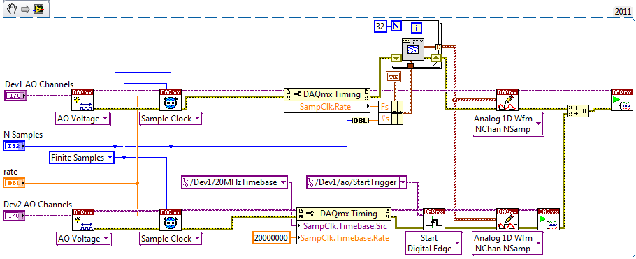
Instead of sharing a sample clock, I must configure your task like this:
In this way each device generates its own clock and do what he needs out of all samples. Tasks will begin due to the relaxation of beginning shared synchronously and will not drift over time because of the shared time basis.
Best regards
-
recovery rates have been deleted - help!
My father inlaw was recently scammed by someone claiming to be from microsoft, out to deprive him of £300, they also with remote access to his computer and seriously messed. I was about to restore it to factory settings only to discover that the D drive, where the recovery disc was stored has been removed. Please can someone help me get this computer working again, I bought the recovery software which did absolutely nothing, it is not possible to restore the system and I am at a loss.
Help, please
Monday, December 17, 2012 07:42:43 + 0000, GillieWallace wrote:
My father inlaw was recently scammed by someone claiming to be from microsoft, out to deprive him of £300, they also with remote access to his computer and seriously messed. I was about to restore it to factory settings only to discover that the D drive, where the recovery disc was stored has been removed. Please can someone help me get this computer working again, I bought the recovery software which did absolutely nothing, it is not possible to restore the system and I am at a loss.
Contact the computer manufacturer and ask them for help. They should
being able to provide a DVD at a low cost.Ken Blake, Microsoft MVP
-
Multifunction analog input/output
I use USB X series 6356 to my experience. I send out a pulse of tone by analog output channel to an actuator.
And receive the signal of response of a sensor to an analog input channel. I've included a screenshot of VI.
The question is, I get the output of the signal response signal as well.
If I send (via the output channel), a burst of your 10 KHz which begins at t = 0.
I see that the tone burst into my plot of input channel as well (at t = 0).
Please, let me know if I use the good VI (I build it according to multi-multifunction-synch I AO VI of examples).
I use the loop to remove 60 Hz noise (by an average of more than 100 times) signal.
Hi Vishnu7,
From what you describe, it seems that you can meet with some ghosting or crosstalk on your analog input channel. Take a look at this knowledge base article and see if it matches with what you see.
http://digital.NI.com/public.nsf/allkb/73CB0FB296814E2286256FFD00028DDF
-
PCI, I / AO at a different frequency
Hello
As a newbie, I met a problem when I tried at the entrance and the analog output signal at a different frequency.
I followed PID-control - Multichannel .vi to build a control program, so input/output can be synchronized. However, the project requires that the frequency of I be tenfold of the AO. I could re-write the while loop to make the output value constant for 9 of 10 cycles. However, in my view, it is simplest way to do.
Anyone provide an example?
Thank you in advance.
Sincerely yours
Ming
lmuri wrote:
Hello
As a newbie, I met a problem when I tried at the entrance and the analog output signal at a different frequency.
I followed PID-control - Multichannel .vi to build a control program, so input/output can be synchronized. However, the project requires that the frequency of I be tenfold of the AO. I could re-write the while loop to make the output value constant for 9 of 10 cycles. However, in my view, it is simplest way to do.
Anyone provide an example?
Thank you in advance.
Sincerely yours
Ming
Hello Ming!
Please use the Forums of NOR. You'll be happy to know DAQmx allows what I/O tasks such as these to be not run not only at the same time, but at different rates.
The problem with the solution that you have imagined is that this implementation will remove the delegation of tasks to the hardware level, and your program would become software-driven; This becomes a problem when you perform tasks of acquiring data at very high speeds as it becomes limited to the speed of your operating system (OS).
You can coordinate your tasks to operate synchronously and perform the output and the acquisition at different rates by creating a maintask. This means generally that you configure a task by DAQmx that keeps a clock frequency and you create tasks that use this clock frequency, or a division thereof, to exploit to their own individual frequency. This facilitated not only the execution of DAQmx tasks synchronous but also provide a material entirely focused on the solution of performance maximimse.
Thanks to LabVIEW, if you go to help > examples find to open the Finder of example of OR. If you are browsing material input and output > DAQmx > synchronization > multifunction > Multi - multifunction - Synch Dig read write with Counter.vi, you will find an example of how to set up a counter as a master of the task to control the operation of operation both a reading and writing . (This example shows a digital but implementation may be easily replaced by analog).
By setting the meter to the maximum frequency rate that you will require for your task (in this case, the speed at which you want to copy values) and apply it to the output of the SampleClocktask, you will drive the clock output task with the counter as the clock source. You can then use the meter as the source of the SampleClock for the task of entry, however to set the rate at any division of the driving frequency. In the case of your example, you can set the bit rate to 0.1 times the frequency counter to acquire a 10th of the rate.
If you want to acquire at the same rate, but only to retrieve values on the 10th of the speed, this same solution can be configured to produce instead a trigger to return an acquisition in the buffer. With a master synchronizing the task, the possibilities are endless!
I hope you find it useful, and if you need a precision more do not hesitate to let me know. Have fun with your DAQ!
-
analog and digital data synchronization
Hi all
I would like to help with what I seek to accomplish, if you don't mind much.
I'm trying to synchronize the acquisition of analog and digital modes using a common trigger that launches both types of data collection at the same time. What I've done so far, is wasting his time trying different combinations to gather examples of LabVIEW 2011 on the synchronization of data - namely the 'Multi-multifunction-Synch AI lu Dig Chan.vi' and 'Multi-Device Synch-Analog Input-Finite Acq-Analog Start.vi.
I tried to combine the two, because one contains digital and analog, the other contains the trigger for multiple tasks.
I guess I should place the trigger (either digital or analog-eventually I will want to choose) then call the "Get Terminal name with device Prefix.vi. But from there I'm not sure wheter to connect the name of the terminal of the sample clock digital channel or a digital leading edge of the digital chain trigger.
Also, the way it is wired now I get errors at the local terminal name, so I don't know exactly where this terminal must come from.
I try my best, I could use a little help, I have attached my attempt with the examples that I speak to you.
Thank you.
Hi beefcake.
The CtrInternalOutput internal output line is used as sample for your digital output sample clock source clock. If you change the settings for your CO Pulse Time is Dev1 and your digital output is Dev2, you will notice that the name of the product terminal would give Dev2/CtrInternalOutput. So what you get here, it's as well as the digital output device sees his sample clock, instead of the clock itself.
If you just want to use a digital/analog input as your trigger, you should do something more as in the example above. Do you use multiple devices, or are all your lines on the same device? This example is more complicated because it is synchronization of signals on several devices.
Looking at how this VI is wired, you can see that the digital signal triggers the analog signal. You want the analogue signal must be started first, so that when the digital signal triggers the analog task is already running and can trigger immediately. If the digital task started first, it can trigger until the similar task had started, and they do not exactly trigger at the same time.
I hope that clarifies things. Kind regards
-
How to sync 3-way with USB-6251
Hi all
I have a NI USB 6251, Labview8.5.
My system includes: + a waveform output stimulating (I use Dev1/AO1 or Dev1 / AO0)
+ Two channels for (I use Dev1/ai0 and Dev1/ai1) acquisition of input signals.
I modified example "Multi-multifunction-Synch I-AO" Find example\Hardware entry and Output\DAQmx\Synchronization\Multi multi-function.
I added a single channel for this example and I want to 3 channels at the same time working, but during process occurs "error-50103 occurred at Task.vi:1 DAQmx Start" or the possible reasons: the specified resource is reserved. The operation could not be performed as indicated.
I have taken a long time, but can not solve this problem.
Can you give me any advice.
Thanks in advance for any help!
MC
As the specifications clearly indicate, your Board does not support simultaneous sampling. There is a simple element A/D and all channels are multiplexed for her. When you select several channels, the first string in the list will be sampled, then the second, etc. There will be a time that you can determine and it is very small, but it will always be there. If you need simultaneous sampling of the value true , you can buy a DAQ card that supports.
-
train of generation of alternative pulse with USB-6251
Hi all
My goal is to generation on the USB6251 signal as output:
http://S232.Photobucket.com/albums/ee262/rusian24h/?action=view¤t=formofsignal.jpg"target ="_blank"" >
http://i232.photobucket.com/albums/ee262/rusian24h/formofsignal.jpg "border ="0"alt ="Photobucket">"


First, I marked VI "generation signal ' (attached fllowing), after that, I replaced under VI"Basic fuction generator"in VI"Multi-Fuction-Synch I-AO"(in the library of examples of Laview) with VI"generating the signal.
http://S232.Photobucket.com/albums/ee262/rusian24h/?action=view¤t=Outputanalogsignal.jpg"target ="_blank"" >
When the program runs, the output signal is last 6 periods of the signal.
How can I output the entire signal?
Please help me
Thank you very much!
Rostov,
Please use the Forums of NOR. I have seen the same behavior that you experience when you place your custom in the AI Multi-multifunction-Synch-AO VI. This behavior is because your personalized VI wasn't out the data you expect. When you wrote your data on you placed him in a graphic waveform and graphics have memory. So he was combining all data in a single chart, even though she was only being written in pieces. That's why when you place your VI in the other program that you saw only the last couple periods. I enclose a VI that I did which will display the step that you are missing, and I used one 'Add waveforms' VI to ensure that all data is saved correctly. If you place this VI in the code you should see everything correctly. Let me know if you have any questions.
I have attached the VI in version 8.6 and 8.0, if you need a later version of 8.0, let me know.
-
My program involves several DAQ tasks that run in unison, as in the example of "Multi-multifunction-Synch I-AO. Works very good in general, but if anything it either never interrupts the flow of the program, I'm stuck permanently with the error 200279. Here is the precise relationship:
Error 200279 occurred at DAQmx Read (analog 1-d Wfm NChan NSamp) .vi:1
Possible reasons:
Attempted to read samples that are no longer available. The requested sample was already available, but has since been replaced.
Increase in the size of buffer, most frequently the reading of data or by specifying a fixed number of samples to read instead of reading all available samples would correct the problem.
Property: RelativeTo
The requested value: current playback Position
Property: Offset
Required value: 0Task name: input analog
And once I am in that State, the only way I can find out is to kill and restart all my tasks. There must be a better way? How to resync the computer firm asking former samples and welcomes those who are there NOW?
Here are a couple of reliable means to bring about this problem: 1. reach a breakpoint during debugging. It's very frustrating when you can't use a breakpoint without destroying the same operation you are trying to debug. 2. the user presses a button that opens a file dialog box. Even though my main program consists of several parallel loops, and the dialog file is called from a DIFFERENT LOOP that makes the acquisition of data. It's a problem anyway. How can I make a file dialog box without stopping my stream of data acquisition along the way?
Help much appreciated. This problem stop my program to be the work of industrial power that needs my scientific users.
Thank you
KenKen,
You can specify DAQmx what samples in the buffer to read. By default, DAQmx will read the 'current reading position. What you see is that the data not read from "current playback position" got too written with new data. Basically the data that was in the 'current reading position"no longer exist, and try to read from that location you causes the error you see. DAQmx does not specify where it reads data since. You can use the property Read DAQmx node to specify what DAQmx reads Relative to, but also a shift here in the buffer. It is possible that if you detect this error, you can read from 'most recent sample' for a reading. This would throw essentially all of the data in the buffer between the "current playback position" and the most recent sample in the buffer, but would allow your application to continue, as it is equipped to address the shortcomings in the data.
Hope that helps,
Dan
-
I just reinstall the operating system on my computer. I downloaded the latest version of Firefox and tried to connect to synch - I have no other devices connected outside of the computer, I just cleaned so I was unable to pair. I tried using the recovery key, but it would not allow me to continue. I tried to log in again, and then he said that my email didn't have an account. I created a new account with the same email that I used before and now none of my info (bookmarks / prefs / plugins) are here! Please help me to recover my previous Info!
Sorry, but the action to create a new synchronization with the same account caused e-mail address your data from the server. In addition, 'coupling' and the 'Sync' button has not been used in over a year, with 28 Firefox being the last version to use the old version of Sync. Then it uses Sync on a device as a backup, something that Sync was not intended to do service
Any chance that you have an old Time Machine backup?
-
I have a project with clips of multi-cames and that they do not play
By pressing space or play on the window of the program button will act as if it is being read (turns into a stop button) but will not. I am using first Pro CC.
I have 17 different time limits all multi-cam. Anyone have a resolution?
Ok.
Update 9.0.2. There was some difficulty big on this issue.
-
detection with high speed HAVE changes at high speed
I'm working on a helmet testrig. We use the card M PCI-6251. An accelerometer 3 axes is set inside the helmet and its fall of variable height up to 3 m. During his fall, I need to gain entrance to the analog accelerometer (sampling > = 100 kHz) and also to find the speed with which he hits the bottom.
How I find the speed is two sensors spaced apart at the bottom of 4cm. When the helmet Assembly passes through the sensors, they become high momentarily and my DI me should get the corresponding time.
It's my problem and also very important part of the program. The data are acquired, for approx. 2 seconds. One entered analog from 3-channel sample rate > = 100 kHz, the second is a digital entry of these digital sensors (two proximity sensors) within 10msec helmet Assembly passes one sensor to another. I can't detect the moment when the sensors go high.
My first test was (fig Acq1) just a spot of digital input to the application. (flags should make sure I have time only once for each sensor). It always gives me the time 16msec difference, 32msec, or 0 for any speed.
My second try was the method of change detection (follow-up of the programs posted on the forum). This also seems to sense only, 0msec, 15msec or 31msec only. This is not true since heights higher than the helmet fell, it is faster, and for these the time difference between two sensors that it gives is zero.
The way I implemented change detection is, I just get of an hour for the first detection of change and second change detection only, where the structure case inside the structure of the event.
is there else a better way to do it?
Thank you very much.
Patricia
I see no reason why you would need external clock. The PCI-6251 card has an internal clock.
I look through the viewfinder of the example for DAQmx examples using analog and digital inputs. I think that might work for you is Multi-multifunction-read AI Synch Dig Chan.vi
-
Trigger digital beginning for simultaneous tasks of HAVE and AO
I am trying to create a Subvi to simultaneously measure 5 signals of HAVE and an AO output signal. The AO signal feeds a diet that feeds in turn my sample. It HAVE the applied voltage, current temperature measurement (via a shunt resistance), via a V 1-5 of a pyrometer optical signal and two other sensor input voltages. During the test, I would also like to vary the applied voltage, so I set up a ripple of tension values. To make things pretty simple I execute the tasks of HAVE it and AO at the same pace, and I want the two tasks to start at the same time. To reach the start of the trigger, I wired an additional set of contacts on the power relay to line 0 on a DIO 9401 resident module in slot 5 9172 chassis (access to the PFIO signal).
Attachment is the base Subvi, I came with to do so. I think it is the task of the AI seems to trigger correctly, but the AO seems to start as much as 100 msec before the start of the task to HAVE it (sometimes it is dead on, but other times not).
Will I put in place these tasks to start at the same time, or is my approach to programming off?
Here's my hardware configuration
1. If you want to start both tasks at the same time and run synchronously, you don't need two digital triggers start. Take a look at the example of Multi-Func-Synch AI - AO.vi in the Finder of the example.
2. Design your architecture using the State machinery rather than using the Structures of the sequence. Take a look at a model of State machine in the file-> New...
-
Hello
I use HP Professional LaserJet M1132 multifunction. I have already installed the driver and I can print document with that now. But I can't using the scan function. When I click on Preferences system-> printers and Scanners-> choose the printer-> click Open scanner, nothing happened.
As you can see in the photo, the "Scan" button is disabled.
What should I do now? Are there additional software or I need to install driver?
Any help is appreciated. Thanks in advance!
Hey @phuonglm94,
Welcome to the Forums of HP Support!
I understand that you have some problems with scanning your computer Mac OS x Laserjet M1132 10.11 for the printer. I can help you with that.
To start, make sure that the printer is plugged directly into a wall outlet, not a surge protector. Once done:
- If your printer is connected by USB cable to your Mac, delete it.
- Close any programs you have open.
- Click on your Apple icon, system preferences and printers and Scanners.
- Hold down the CTRL key and click the icon of your printer on the left.
- Click on reset printing system.
- Restart your Mac.
At this point, you should be able to scan. If you are unable to scan, your operating system is having a problem with its TWAIN drivers. The next step would be to contact the Apple support by clicking this link.
Please let me know the results after following the above. If you are able to scan, click on accept solution. If you appreciate my help, please click on the thumbs up icon. The two icons are below this post.

Maybe you are looking for
-
I want to know.
-
proplems with the new synchronization
HelloI have been using the synchronization of the former and I have my key but all of a sudden, I have to format my pc before upgrading to the new syncnow, I installed the new version and made a new account but I need to restore my settings from my o
-
Cannot find the BIOS for Satellite 1900-803
Hello I have a Toshiba satalite s1900-303 (model number-ps192e-00g1n-en) and I'm not.I have somehow locked myself out of the laptop. I used to haver a password to use the laptop. This password is not only for the bios, it is also necessary for the op
-
How can I convert a LabWindows/CVI 2010 project to a Visual Studio 2011 project?
I have a good size project, 12 source files, headers 14, 1 uir, I want to be able to edit and compile in MS Visual Studio 2011, MSVC ++. I remember that we tell him that LabWindows dropped support for C++ in 2008 and is more had a wizard to convert p
-
Windows cannot repair this computer automatically
Original title "Help? Laptop used to start.My laptop was working fine and then I went to turn it on and it keeps trying to windows startup repair and then says "windows cannot repair this computer automatically" if I click on problem it details reads