Multiple Ukraine power measurement
Hello
I use the card Ni SMU 4143. I have a VI that propels a certain voltage level card. Now, I'm trying to create a separate VI which will only measure the voltage and current on the power supply without a reset provision. I understand that I must "log on" to the device before I use the "power measurement multiple.vi Ukraine", but whenever I use the session initiate, it will my device and set my level of back tension reset. Can you please explain how I can create a VI that measures only the voltage and current without changing their level?
After the opening, why don't call you the VI that determines the level? Not this separate VI also call the lance function? Think that the flow of data.
Tags: NI Software
Similar Questions
-
cDAQ-9174 with modules 9225 and 9239 for issue of power measurements...
Hello to one and all.
I do turn a cDAQ-9174 with modules 9225 and 9239 to measure the voltage (120, 208-240, 277 VAC) and current (via the clamp amp i400, Fluke - 10mA/exit A) respectively.
I have the set scale scale Differential No. (1:1 I guess) for 100: 1 for current and voltage. With the acquisition mode set to "N samples", 10 samples to read, at the rate of 500 m. This feeds into 'EPM_Power.vi' (polymorphic VI of the palette of EMP... can be downloaded here, http://sine.ni.com/nips/cds/view/p/lang/en/nid/209826)
I try to check my numbers with an Analyzer of power quality of 435 Fluke and supporting that upward is a Fluke 179 True RMS DMM with clamp amp i200 (for current playback)
Now, I'm running is my numbers I take data look like they're following a curve of fishing... the averages are on the right, but when my blood pressure is expected to be relatively stable, it's over the map... same story with my current readings. I tried several different filters without success. I would like to have relatively stable values for voltage and current so my other values are correct. Is there a signal conditioner or filter that will help with this?
As always, a point in the right direction would be greatly appreciated!
Thank you!
Chad
Hi, Will,
Your request for a screenshot actuall lead me to the solution. Not enough samples! I took little data too slowly and only seeing part of the wave of fishing AC each iteration. .. that became glaring when I tried to this graph. So I increased my sampling of 100 to 5 Hz and things seem to have settled things down a bit. Thank you for the good question!
SH?
C
-
Can we average channel error using multiple channels to measure the same voltage?
I don't know how correlated error terms are between measuring channels max, but it occurred to me that, if they were relatively independent, I might be able to sample the signal even with several channels and increase accuracy.
For example, rather than measure a voltage with an AI only at 100 kHz, I could connect up to 10 different lines to HAVE the signal, sample to 10 kHz on each line. This should allow to reach me on average some of the error associated with each channel (, or so I think).
Can someone speak definitively to this?
Thank you
Sean
Well, if you are using a MULTIPLEXED Board (everything is not specced for simultaneous sampling) then each channel is connected to the ADC even one after the other, best that you would be able to do is extremely, extremely small variations into the paths of each channel of the multiplexer. This would still be massively overshadowed by the inherent noise from the system and the accuracy of the device.
Your best bets to reduce the measurement error is to oversample in one way to reduce the effects of noise and to calibrate the unit before starting each test to keep variations of temperature. In addition, make sure you keep your calibrated Board (most of the boards have a calibration 1 year of the cycle).
For some applications, you should also consult wiring field and considerations of noise for analog signals, How to eliminate ghosting of my measurements? and Troubleshooting unexpected tensions, floating or crosstalk on Analog Input Channels to better account for ghosting and the issues of the hour.
-
-
I downloaded the new photovoltaic analysis tools and when I open it it fails to find something to do with «the niDCpower...» VI.
Points that are for any file beginning with the phrase, it starts with "property close.vi" and moves.
Any help would be great, I'm very new lab mode have just begun my PhD and never used before.
Thank you
Simon
Hi Simon,.
Hope you are doing well today!
I understand you are trying to run the Toolbox found no of screws OR-DCPower required even if you have already installed the drivers. To allow me to help you further, you give me the following information please:
- Without trying to run on the screws of the Toolbox, you are able to find the screw of NOR-DCPower in the Palette of functions - Instrument of e/s - Instr pilots - OR-DCPower Palette? See attachment below for the screenshot. Have you also tried the search to locate?
- What operating system did you use and what version of NOR-DCPower drivers you download and install? The latest version is 1.2.2 and can be found here.
Please let me know how it goes,
Thank you
-
Measurement time 4132 SMU is too high
Hello
I use PXI - 4132 DC EMS to perform some DC measurements at high speed. I just took a 1 K Ohms resistance, forced 1mA and measure 1V. I have this done configuration and code completed. I get the correct measurements. But my problem is with the measurement time. The total duration is about 45ms to complete installation and measurement, with the exception of the 'initialize and close '.
I checked the time at every step and I noticed that the maximum duration is taken during the "voltage reading. Out of the total 45ms, it takes about 34ms just for a measure. It's just a VI "Ukraine power measure" takes about 34ms, which is ridiculous compared to the Kiethleys. I tried to vary the time of "openness" and turn off the 'Auto Zero'. But the measurement time is still high. Can someone help me and let me know what is the best time of the measurement obtained with 413 x series SME?
Thank you!
Hey Phx_tech,
The amount you reduce your delay source depends very much your HAD and how regular you have to your level of tension until you start taking your measurements. If your Instrument is reactive, you can see discount gas and unintentional ringing during the transition from your output level and therefore would allow enough break-in before taking your measurement. The best thing to do is to experiment with different delays of source and see how much delay need you to get a consistent and reproducible measure. If you have a scope that is available, it will also show you the step response of the SMU with your Instrument. If your first reading is higher than your other readings, that this could very well be a problem with not enough time settling. What kind of DUT Testez_ you?
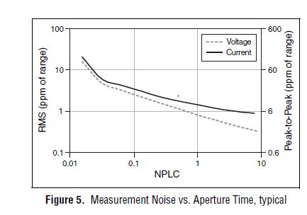
From page 4 of the specification, you can see that 1 PLC, we can expect about 1 ppm RMS noise of the range to 1 PLC. This means in the range 10 au our measurement noise would be 10 pA RMS or 60 pA pk - pk. However, your DUT + cables will pick up the extra noise and you should consider using wires of twisted shield pair to reduce noise picked up in your system. The shield can be terminated at the mass of the chassis on the side EMS of the cable to help reduce noise appearing in your measurement.
Let us know what you find after experimenting with you HAD.
Thank you!
Brandon G
-
Measure the power takes too long
Hi all
I use Agilent 8163 b with 2 slots: 81619A (2 heads) and 81618 a. (1 head) for power measurements. I have set up my measurement with driver Setup for the time of Agilent vi to the average duration of 5 seconds. However, it took total more than 20 seconds to complete the measure of 3 channels using Agilent 816 x reading PMW Value.vi (this VI calls a DLL hp816x_32).
My question is that can I get this measure nearly 5 s with a parallel read 3 channels at the same time? I.e. the reentrant hp816x_32 DLL?
I tried to have a wiring in parallel of 816 x reading PMW Value.vi to test this, but still get a time of 21 seconds measures. Anyone have a suggestion to improve this?
Thank you
Bryan
I'm not familiar with this specific material. But how much time does it take if you only measure a single channel? If it also takes 20 seconds I guess that the vi is to configure the device whenever it works (it is a painful overload). You can go down to the Basic by using the READ and FETCH commands? for an optimal speed on similar devices (I don't remember too much syntax).
Felix
-
NI9225 waveform measurement of network 230VAC
Hi all
I measure the waveform complete (time of the voltage signal) the local power grid with a voltage of 230V L1 - N with a NI9225 module.
Peak values (RMS) 230VAC * 1 414 = 325V pic.I can't to scale greater than + 300V M.A.X parameters entered.
In the statement indicates that the module can measure 240V electric networks.
Can directly measure the shape of wave or shoul, I use a 01:10 for measures voltage divider?
Thanks in advance
Regards Christof
Text of the Manual:
The NI 9225 300 module input analog Vrms C Series has been designed for the waveform of signals measures high voltage. The Vrms 300 range allows line-neutral as a line of measures of electrical of 110 V and grids of the 240 line-neutral networks V. Three NI 9225 channels make the ideal module for a three-phase system. Measures voltage waveform are required to follow events like sag, swell, transient power quality and harmonics. Combine the 9225 OR with the NI 9239 (10 V) and a current transducer to create customizable power quality monitor or a power measurement system.
Die Skalierung as AC measurement wenn ich die richtig Spec understand habe ist.
BIS + / 425VDC ist der range sogar in der Spec angegeben.
Also im bereich messen und deine Wfrms bekommst 300V 240VAC mit schönen Sinus...
No vote was now a screw also as Poweranalyse Schön mitkommt, aber your über etwa 15 Perioden so sicher detection...
10:1 Tastkopf kann nicht schaden, if abgeglichen.
Offenbach... VDE?
-
Hello
I want to meausre voltage, current and power of a vacuum cleaner 220kW AC for Lab View. Can anyone help in the material side that all the components I need. I have little knowledge about it.
Cecile
Do power measurment the current and voltage must be sampled at the same time, in the same clock cycle. Most of the DAQ hardware NOR has a single ADC and they workpieces between channels quickly with a MUX. It will not work for you, and you actually use a simultaneous sampling equipment. Here's an article that talks a little about it.
http://www.NI.com/white-paper/8198/en/
Basically, for this example we measure voltage of phase 3 with a 300 Vrms 9225, 3 put in current with a 92275ARMS phase, then a unique, the cheapest cDAQ chassis is a 4 connector 9174. If you need more power or voltage, then you need sometimes a kind of buffer that can convert your high voltage or current in a - 10 v to 10 v and use a 9239, then scale it up upward with the software.
Oh and if you want to get real fancy you can buy the power suite software too.
-
HP pavilion p6 2310: upgrade of the power supply
I was wondering if this diet will enter my pc hp pavilion p6 2310
http://www.NCIX.com/detail/EVGA-500W-80-plus-certified-5F-92643-1563.htm
Power supply I want
Hello
The standard ATX HP power measured 5.9 by 3.4 by 5.5. As posted by your link shows a good fit.
An examination revealed a problem of quality control
 but the other customers looked good.
 -
Greeting,
My PTD partly work stoppage. I do not want to test the power
so vmmark2.cfg, I have a PTD = 1 line try to stop him, but the work has been stop here, how can I just passed the test of power?
# -------------------------------------------------------------------
# Configuration power settings
# PTD = 0/1: valid [0/1] toggle values
PTD = 1
# PTD_Clients: STAF compatible systems connected to power measurers
# Note: The number of PTD_Clients determines the total number of PTD
#: active process. 2 clients would require 2 ports, etc..
# PTD_Target: Classification of the measured elements (SERVER or EXT_STOR [storage])
# PTD_Ports: Port used for each meter.
# PTD_MeterTypes: counter for each meter Type.
# PTD_COMs: COM Port for each power meter on its client PTD.
# PTD_Ranges: allows to define the ampere per meter ranges.
# Ex: PTD_Client:PTDclient1-> target: SERVER-> Port: 8888-> MeterType:8 (Yokogawa)-> COM:COM1-> range: 4.0
# Ex: PTD_Client:PTDclient2-> target: SERVER-> Port: 8890-> MeterType:8 (Yokogawa)-> COM:COM1-> range: 4.0
# -------------------------------------------------------------------
# PTD = 0
# PTD_Clients = "PTDclient1 PTDclient2 PTDclient2 localhost.
# PTD_Target = "SERVER SERVER EXT_STOR EXT_STOR.
# PTD_Ports = "8888 8890 8892 8894."
# PTD_MeterTypes = "8 8 8 0.
# PTD_COMs = 'COM1, COM1 COM2, COM4.
# PTD_Ranges = "" 4.0 4.0 4.0 4.0 ""
# - Optional parameters - indicated default parameters
# - WARNING: changing values can do resulting runs non-compliant
# PTD_RampTime = 1800
the result of the test
20130730-23: 54:57 No. PTD Clients past:
20130730-23: 54:57 UserSpecified: PTD customers = "
20130730-23: 54:57 PTD Ports spent less in number of PTD_Clients:
20130730-23: 54:57 UserSpecified: PTD Ports = "
20130730-23: 54:57 PTD MeterTypes spent less in number of PTD_Clients:
20130730-23: 54:57 UserSpecified: PTD = MeterTypes "
20130730-23: 54:57 PTD COMs spent less in number of PTD_Clients:
20130730-23: 54:57 UserSpecified: PTD COMs = "
20130730-23: 54:57 ranges PTD spent less in number of PTD_Clients:
20130730-23: 54:57 UserSpecified: ranges PTD = "
20130730-23: 54:57 PTD target spent less in number of PTD_Clients:
20130730-23: 54:57 UserSpecified: PTD target = "
20130730-23: 54:57 ends job due ptd configuration errors: PTD target spent less in number of PTD_Clients:
20130730-23: 54:57 call VMmark2.5 Growler
20130730-23: 54:58 VMmark2Msg closing job due ptd configuration errors: PTD target spent less in number of PTD_Clients:
20130730-23: 54:58 VMmark2Msg: timeout of 300 seconds automatic Message
Thank you
Newbie
PTD = 1 allows power measurements, you want to set it to 0: Ex PTD = 0
-
How can I remove the split screen?
I changed I OS 9.2 and it has a split screen, I have to delete. It's awful. It is difficult to see the right side of my screen. There is not enough room.
Try the settings > General > multitasking > allow multiple applications > power off.
-
Is it possible to read the voltage/current SMU after the closure of the original session?
What is the method, or is it still possible reading the voltage and current of an SMU SMU-4138 measurements after the original configuration session has been closed? I have a (relatively) long Teststand sequence that sets up the EMS to provide power to the ESA, then conducts tests and along the way I have to take the readings of SMU. I was always under the impression, it is advisable to open and close the EMS quickly set up, but the 3-State programming model does not allow a way to jump into the running state of Init with channels VI, except through committed and engaged States and thus any stop in the process. The power measurement VI only works if you are in the Running State. Seems like a no-brainer, so what Miss me?
bholsinger wrote:
I was always under the impression, that it is recommended to open and close the EMS quickly set up
It's BAD advice. You open at the beginning of your program, you do whatever it takes with it inside your test (configure, read, etc.) program and you don't log off not until you stop your program.
-
HP 70950 osa and 8163a multimeter
Hi, I'm new to this forum, I'm looking for help to create a Labview basic program to communicate with an old HP70950A optical spectrum analyzer, connected via GPIB to a Win98 computer where Labview 6 is installed. There is no pilot available, but just the BASIC HP Manuel. I would get through the usual PLAYBACK controls / WRITING, the amplitude of crest of slider and, ultimately, the wavelength. Any additional command to control the instrument is welcome.
I'll get these data according to the power measured Agilent 8163 a multimeter, for which it has the drivers already.
Thank you
Antony
antony_sc wrote:
which function to use to succeed in the Labview program? RECEPTION following the SENDING does not work. I tried to play with time, to see if it is a problem of communication, but it is not.
My view is bad enough already, so if you could be kind to us old people, could you use a normal font in the future?

Well, the receive function would be the equivalent of the function in LabVIEW. What do you mean by "it doesn't work"? You get an error? If so, what is this error? Still, I would agree with Dennis, you must use the VISA.
-
Scenario:
We have a deterministic loop on a target RT (OR PXI)-. The need for speed at 1 Hz only with as less as possible jitter. This deterministic loop will execute measures picoAmp with many units of Keithley6487 (using low-level SCPI works, so all control configuration of measurement devices, then "INIT" (takes about 2 msec per unit) and approximately 300 msec later "fetch" data from the Keithleys (requires approximately 10 msec per device).) This deterministic loop will be a state machine and accept orders from lower priority loops (as zero check, reset, etc. a Keithley or multiple). The measured data will be in the form of double table, so it's OK for the communication between the RT FIFO loops.
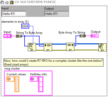
However I am wondering how to extend the functionality: measurments a warning might be created by Keithley screw as a string. In addition, an acknowledgement of receipt/feedback some actions performed on the Keithley should be reported to low priority loops again in original form they are strings. The chains are not supported by RT FIFOs, but I found this tip below how convert it (see below).
In order to disseminate all the information correctly, I think that I should send it measure in the form of a double array data, and an array of strings size even that would hold all related SCPI in guard/acknowledgements of Keithley units. Since I can't use cluster either to RT FIFO, y at - it something to 'compress' or convert the type of cluster complex into something RT FIFO compatible?
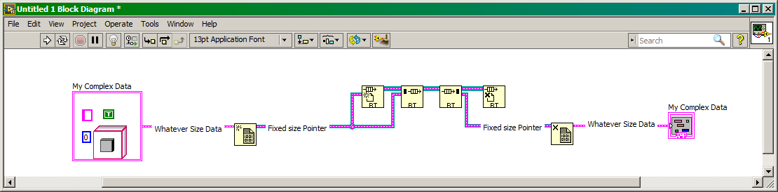
Right now I think just a workaround solution: I could create two RT-FIFO, double for the data table, and the other using the trick below to convert string (all two fixed sizes). I could convert the array of strings of information Keithley in a single string delimited by commas, I can use the function 'String into byte array'.
All tips and suggestions are very welcomed!

WARNING: I am a beginner in the field of the RT...
During the initialization of the RT-FIFO instead of using an array of fixed size, use any format you need for your data, but before you pass it to the function "Create FIFO", use the "Create new DVR" and what reading use the "Destroy DVR" feature to pick up your package of data of arbitrary length.
Maybe you are looking for
-
Impossible to install the module
I try to install ixquick or homepage of the Firefox Add-ons page, but I get the following text: «Sorry, you need a browser based on Mozilla (like Firefox) to install a search plugin.» OK ". even if I use Firefox on Ubuntu LTS 14.04 38.0 Any help woul
-
I have a recently HP Compaq CQ58-201SA with whom I made the stupid mistake of letting windows store to go ahead and install the 8.1 update. Everything seems very well went with two obvious questions. (1) edge LAN 'Realtek PCIe FE Family Controller' (
-
HP mini 110 reset bios password
my serial number cnu9410728 ı need your help pls
-
Windows mail Inbox messages began diappearing
I have windows vista comes with windows mail... My Inbox messages began to disappear and do not appear in the deleted items, or any where.where they go and how do I get this to stop. Also, someone said that windows mail updated to windows live mail
-
Sailing with the Injection of the event guests
I try to use the event at some point injection back a prompt for the user. Now, however, just trying to get so that when the user clicks on my application of simple test on the home screen, the cursor goes up a line. I use the injector of the event