Multisim: Parameter Sweep of piecewise linear voltage source
Hello
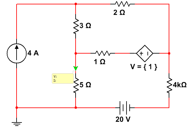
I did a transient analysis of a 4-stage-amplifier with a certain input pulse generated with a piecewise linear voltage source (screenshot 1).
Now, I want to do a sweep of parameter analysis by varying the amplitude of my generated pulse.
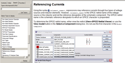
What is the right for this parameter? (screenshot 2)
Thanks in advance,
Johannes
Hello
You will not be able to do sweeping device/model parameters because the Amplitude of a pulse source is not actually a device/model parameter.
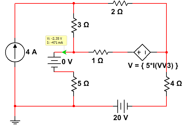
For this, use the parameter of Circuit of Mutlisim feature. See the circuit attached for reference.
I defined a new Circuit parameter (view-> parameters of the Circuit) called "Level" with a default value of 1.
I assigned this setting to the "Pulsed value" parameter of the element of impulse voltage source.
In the dialog parameter Sweep, I chose the Circuit parameter as the type of the parameter I want to scan, and then I selected the parameter 'level '.
I would like to how it works for you.
Tags: NI Software
Similar Questions
-
PIECEWISE LINEAR VOLTAGE Source BUG
I want to source PWL allows to analyze signals from my digital oscilloscope.
File MEANDR.txt contains 5000 points of voltage (mV) in the time domain.
(1) if I'm going to use this file with the option 'Use data directly from files' there will be no signals at the output of the source.
(2) if I go use the option "enter data points in the table---> Initialize the file" and press the button "Run the Simulation" Multisim breaks down... but it starts working properly if I'll burn the original file of 5000 points to 2000-300 points. (File MEANDR_MODIFIED.txt)
You can fix this bugs?
Thank you!
Hi, ZG,.
Your data will give Multisim a problem because of the format, Multisim expects the tension and the time of two columns. On the column of time data range from 1 to 5000 so Multisim will have to simulate for more than an hour and in the world of simulation that is an eternity. I changed the data so that Multisim simulates only up to 5 sec. Your column of tension is supposed to be in mV on each line, you will need to place a mili at the end otherwise Multisim going out KV. Using Word and Excel, I changed your data to something that Multisim may include and the file is associated.
-
Calibration with the voltage source - float connections
Hello
I want to calibrate a PXI-6133 DAQ with a floating voltage source. It says in the manual of the calibration connect the positive output of the Stallion to the AI + pine. Since my source of tension is floating I connect the negative output to GND. HAVE I - HAVE GND short or leave - not connected?
Thank you
Jens
Sorry, I just answered this question for my part it is logical to short-circuit the entries HAVE - and GND.
-
Agilent U2722A linear voltage ramp
I am currently writing a LABVIEW VI to interface with an Agilent U2722A. I want to measure current constantly while maximum increase of voltage of 0V to a defined use specifying the step size and no time (a linear scan of tension).
I downloaded the driver for this device which also includes an example used for output and then take action. My first problem is that when I run this unit VI is to expire. I think that this issue MAY have something to do with the entry "triggered the level". Happened to configure voltage channel VI. I have included the example and the voltage setting channel Sub VI.
My lack of understanding for the other SubVIs (which are based on being passed SCPI commands by VISA as strings) also prevents me from making progress. Especially the scan configures and configure trigger screws
Scanner Confgiure takes the values for the number of points and the timestep. I don't know how I'm supposed to make use of this VI. Should I put the values you want, and then use a loop to pass different values to the chain tension set up with each iteration. Also, how is the measured timestep? I need to set up a trigger to measure the time between the points or the scan function takes care of that? I've included the sweep set up VI as the Timestep VI as well.
Looks like that you've got another error in connection with the IO instrument. Here are some references for this error,
-420, "request not COMPLETED;
This error occurs when you addess the instrument to talk and he has nothing to say.
The most likely causes are:
1. do not send a query. You must send a valid request to the instrument before talking to talk to him. This is true even of the instruments of measurement, such as the 2001 model. You can not get a reading from 2001 until you send him a request.
2 send an invalid request. If you sent a request and still get this error, make sure that the instrument treats the query without error. For example, send a bad request that generates an error - 113, "Undefined header" and then treat the instrument to speak will generate an error-420, "Request not COMPLETED" as well.
3 query invalid due to an invalid command.
Currently I do not have an instrumetn in hand so I can't understand what is exactly what's wrong, but would you mind to paste your code so that we can look into it together?
The most accurate method is absolutely one provided by the material itself. Here is "Interval" in configure Sweep.vi.
-
Branch voltage source currents abm
Hello
How to access the current through resistance in the voltage ABM source?
I finally managed to access the current through the resistance. Others may see "Common SEO" in the Multisim help.
-
Sorry - hopefully an admin can move this to the correct forum. I could find no community forum labeled converter so no idea where to post this message.
My first time trying to use the converter. Use the latest version of the Converter 4.3.0 to try a P2V by using the source computer. This is a laptop Dell D820 running Windows 7 Ultimate x 64 business. I chose the source machine and all the default settings. Destination product is VMware Workstation 7.x and target files are either local or to a port USB drive (tried both). In the last step, I get a yellow bar with the error "the specified parameter was not correct" "but the following quotes are empty and presume it suppose to say the name of the setting.» The only thing I see that is suspect is that if I click on change in section 'Data copy', the list of volumes and empty and assume that shouldn't be. The sample video to get advice on the use of converter on VMware support sites show a volume listed here. I tried the same approach on a completely different system under Vista SP2 and still no volumes appear so maybe it normal?
No idea what I am doing wrong? I did export logs and watch and it appears no volume information has been captured (a lot of & lt; destroyed & gt ;) but even once, just guessing.) Any advice would be appreciated greadly.
Thank you
Don
I had the same problem on a Win7 x 64 machine... There was no listed disk to convert.
I managed to solve the problem by running the converter as an administrator. Right-click on the Desktop Converter icon and select run as administrator.
The disks appears and you can select which can be the converter.
-
Piecewise linear function fitting
I have data which approximates the following function:
f (x) = A; x<>
f (x) = Bx + C; E<><>
f (x) = D; x > F
I am using the non-linear adjustment function and problems with a singular matrix error. According to me, I approached my settings quite well and the best track of the fitted curve seems fairly well aligned, but it seems that's not iterate through my approximations E and F and just using what I give him. Could someone take a look at my code and give me some additional tips? The points that I particularly need are the value 'A' and when f (x) = 0 of the second function. If there is an easier way to find these values, I'm all ears.
Thank you
Yes, you have only four parameters.
- Beginning level
- End level
- first x
- second x
(interpolating linearly between the first and second x from the first to the second level).
See attachment for a quick project.
-
Hello guys,.
My question is provided in the topic, you have an idea about that? your help is appreciated.
ELA
Hi Ela,
For almost all devices supported by DAQmx, you can't. When all AO channels have the same motive, connecting them in series would be short the output channel on the ground, which is bad.
However, there is one exception: the SCXI-1124 module has channel-to-channel isolation, which allows channels to be cascaded to output voltages: I can cascading the output voltage of an SCXI-1124 module?
With channel-to-Earth isolated peripheral (such as NI 926 x or NI 623 x), you can cascade multiple devices together, but not multiple channels on the same device.
Brad
-
Non-linear voltage with current variance
[10/07/2014 edited by moderator as requested]
I'm trying to measure the design resistance of the voltage across my test using NI9205 sample. I have a power supply current constant and 30 cm of wire across copper as connectors to my example. I'm exploring various levels from 20 to 500 my.
However, the resistance or voltage/current ratio do not seem to be constant on current values. Current increase seem to increase the resistance of .01ohms.
I change the lines in my daq between 200-1-5 a 10 V.(+-) of heat due to the current, and changes in the sample of it are not a factor. Is that an offset voltage when changin ranges that affects it? I use the daq with no custom scale Wizard. I do, however, collect samples from 1000 to 1000 Hz and their average.
Tried to use 4 wire measures?
0.01 ohm in 30cm copper wire... seems reasonable...
so: two sons for the current and two sons for the measurement of voltage (differential). Guess the image below that is screwed is current and voltage

-
HP and/or Techtronix Multisim and GRAPHER
Is there anyway to have the results of the Tecktronix and the HP o-scopes in Multisim appear in the Grapher? Not sure why they don't, but they do not.
Hello
Impossible to Multisim to connect directly with third-party tools and import signals from the scopes in Multisim. If you are able to get information on the scope and create a file .csv with this information, you can import this file in Multisim.
I got this from another forum.
"The Piecewise linear (PWL) source accepts data as the voltage or current time. You can find this part by selecting site > component, go to the group 'Sources' then select 'Sources of voltage Signal '. Place this part on the working area, double-click it and there should be an option to open a .txt file.
-
Hi all
I am currently using Agilent E3646A dual output DC power supply.
I'm sweeping the 2 output voltages by using 2 loops, 1 inside the other.
The attachment shows the connection that I have.
However, only the inside of the loop works. The outer loop, seems to work on the Panel before labview, but it does not change the nominal voltage of E3646A.
Any help? Or is there a connection error? I'm new to labview.
Thank you very much!
Dear Daniel,
Thanks for your suggestion.
I moved drivers in loops, leaving the initialization and the error/close to the outside, and it works.
Thank you much for the help

See you soon
-
Source of voltage controlled blow - once
Hello
How can I set the width of the pulses produced by the one-shots-controlled voltage source? Place IWant to 0.4 sec
Thanks in advance,
10CHAR.
-
1V - 5v linear output using power supply 5v, voltage divider, and variable resistance
How can I get 1v - 5v output linear using power supply 5v, voltage divider, and variable resistance?
Have the you wired as an attachment? Using my schema, you can calculate the current flowing through the pot based on the fall of the tension in the pot
4V / 10Kohm = 0.0004
Kirchhoff's current law, we know that the same current flows through the circuit so now we can calculate the leg below the wall, based on the current and the fall of desired voltage across the resistance
1V / 0.0004 A = 2.5 K Ohm
My scheme maintains the current flowing through the circuit of constant, so the voltage divider must never change. Assuming a linear pot, you will get a swing of such linear voltage as measured at the wiper. If you wired the pot, a different way, then more then likely, you change the total resistance of 5V ground that would have the common effect that would effect the tensions.
-
How to model generic spices work in multisim?
I have a model external Spice, I need to use occasionally. I alsways have trouble with that. It doesn't seem to be because I don't understand the models or how operation spices, but more than the conventions to set and get properly hanging nodes and other aspects of MS are ambiguous to me.
This is a model of NTC thermistor and a multisim schematic, I'm working on. I tried many things but you do not have the errors go away. I put back the way I started here.
This model is:
http://www.ecircuitcenter.com/circuits/therm_model1/therm_model1.htm
Can someone explain how to get this model of thermistor NTC to work in MS?
The ramp from 100V to 1V/s source matches the entry of temperature to the model. (0-100 C, 1 ° c/sec on the grapher, if I ever get there)
Thank you
David B
Hi David,
I think that you pasted the netlist any data on the Web page in the Multisim Components Wizard. I think that it is the root of the problem. You just enter in the wizard components are really, the following lines:
. SUBCKT NTC_10K_1   1  2  4  5
ETHERM	1-3	 VALUE = {I (VSENSE) * 10 K * EXP (3548 / (V (4,5) + 273) - 3548 /(25+273))}
VSENSE	3	2	DC	0
. ENDS
The remaining lines that are given to you generate the stimulus, as the voltage source that you placed in your schema.
I have corrected it and attached the circuit has been fixed. Open this in Multisim and simulate a click > analysis > DC Sweep and click on simulation. You should see the curve IV of resistance NTC operating at different temperatures.
Hope that helps.
-
Activating/Deactivating IEPE power switch for voltage 9234
I use this material: NI USB9162 or cDAQ9172 with the NI 9234 module. I want to be able to select weather to use regular accelerometers or IEPE accelerometers with the 9234. I built a LabVIEW Vi where I want to be able to configure the channel of the accelerometer as a voltage channel and input sensitivity data later. Here are my experiences:
- If I use "Voltage Custom with excitation" I get the message "no device supported found. What happens in MAX 'task to create', labview DAQassistant or 'DAQmx create a channel' + 'personalized with excitation voltage.
- If I use 'DAQmx create channel' (with or without excitation) and define the source of excitation and value as a property I still have the same problem
- If I do as well as in 1, but with the acceleration I don't have no problem Iex source parameter and value. But this isn't what I want.
- If I use "IEPE the enable" inside the MAX test panels I have no problem using the IEPE accelerometer and get the tension
The problem is that you are using HAVE. Excit.DCorAC. This isn't the right to property. AI. Excit.DCorAC must be set to DC for the 9234, by default.
If you want to configure channel matching, you must use I. Mating. You can get this in analog input-> General Properties-> entry Setup-> coupling
If you want to configure each channel separately, use Active Channel in the node of your property to select a channel. All the properties that you configure in this node is not available for the specified channel.
Maybe you are looking for
-
Hi I buy chips 4900 rupees today. For the game teen patti app unlimited The cut on my account but not received money chips game please help me as soon as POSSIBLE. Thanks and greetingsAshu Khatri
-
Output USB amps and the voltage on the Satellite A100
Help, please. I have a device that recharges its battery via the usb port. It only came with a car charger which has an output of 5 v 1. 0a - what is the output voltage and amps for my Satellite A100 usb port?
-
Cannot install anti-virus, Windows Installer corrupted software
How can I fix the windows installer? * original title - my windows installer is damaged. I can not install a version of my anti-virus software. Can I get the disc to reinstall Vista? My computer has been preloaded from Best Buy and I do not have a di
-
My internal WD10EADS 65M2BX failed. How can I get my original HP software to put on my new HD?
My HPE-120f came with a WDC WD10EADS-65M2BX installed with Windows 7. It just crashed and I can't get it back. So I installed another HD with Windows Vista, hoping that I can at least see the other HD and get my software off of it, but NO, it does
-
I can not turn windows Defender, error 0x800106ba
original title: so many problems with my PC, help? Please... Remember - this is a public forum so never post private information such as numbers of mail or telephone! Programs: thank you very much for any input. You have problems with programs Error