my project is to measure the voltage and current by using the view of laboratory.
Dear Sirs,
I have a project to measure parameters electric ac current, voltage, power factor etc through aquisitioin of data with labview. Can I do this? If yes then kindly help me with some opinions and ideas. I'll be very grateful to you.
Muhammad Azam Hanan.
Student of the University of engineering and Technolgy, Lahore, Pakistan.
Tags: NI Software
Similar Questions
-
How to display the voltage and current of synchronously
Recently, doing a project on the acquizeing voltage and current synchronouly, then display. the design is welding a resistor(1%) 0.5 ohm in NI 6251 entered analog of her HAVE differential, then acquired the differential voltage at the input to convert current. At the same time, I hope to recover the path of analog input voltage. My problem is that the current profile data. Please help me .the program screenshot is show below. ---1. Perhaps you ask why not use no. - a way to get voltage at all port of AI, then in the use of the software less to get a voltage inputs HAVE. in this way, my problem is solved. I try, but the current accuracy is failure. because my current range expect is 1uA ~ 100mA. precision current samll won't be promised if you use simple ways for granted NOR 6251 voltage. NEITHER 6251 device spec (HAVE an absolute precision) (v) nominal range sensitivity absolute Accuracy (uV) 10 1920 112 5 1010 56 2 410 22.8 74 0.2 6.4 0.1 52 6.0 (I want to use this range to measure current samll) - cordially Shawnh.Chen
shawn1 wrote:
1. how show the waveform by accumulating 1 d data table, rather than showing all 100 acquisitionUse a waveform graph. Graphics keep history, you do not have to accumulate the data. He does it for you on the screen.
shawn1 wrote:
2. What is the minimum unit of identification of the TSC103IPT amplifier? I doubt that the 0.5uA can be identified? (0.5uV = 0.5 ohm * 1uA) Because I can't find anything on the auccary in TSC101IPT datasheet.The amplifier is analog. Thus, he can win anything. But you should really think about a higher resistance if you really want to measure this small of a current.
-
calculate the symmetrical components of voltage and current
Hi all. I work on the calculation of symmetrical components of voltage and current in Labview. I have included the relationship between the symmetrical components and sequence as photo 1 voltage. I'm going to use this calculation for several times, so I wonder if anyone has some ideas far better bc I wired just so much together to realize the expression. It seems aweful. Any suggestion? as built-in function to achieve this function? Thank you
Let's take a look on your form (you don't say what is complex, etc, so modify as needed)

For example, here is how you create the matrix A to an alpha given.

Similarly, you can create A ^(-1) matrix (your definition of A and A ^(-1) seem incompatible, otherwise you could just pick matrix inverse of A). After that, you can multiply with you V123 vector using AxB.
-
Chroma DC power supply RS232 communication (read problem of over-voltage and current)
Dear all.
I chroma programmable DC power. Based on the programming of the Instrument manual I develop using RS232 communication. Based on the program I can set the voltage, current, over-current protection, protection against overvoltages and make IT / OFF out put supply perfectly.
But I have to read the measured values of the output power as current and voltage. Measured applications are the voltage and current of the output of the power supply. My problem is two of them read at the same time. Currently, the reading is only voaltge or current (if the first request is v? it is voltage read out but no reading for the current) and if the first request is CURR? the reading for the current, but not for VOLT? The status message is OK, even if it is to read values.
Thanks in advance
What I see in your program, it's that you do not use the stop for reading character. For your writing, you do the hard with all these concantanate string functions. You can set the stop character for all entries with a node unique propert - "ASRL end Out.
-
scanning voltage and current measurement for Keithley 2400
Dear all
Hello
can someone help me?
Despite days nearlly10 I am option to find any program LabVIEW 2010 for sweeping the voltage and measure current who works with RS-232, I have a end not have nothing exept examples read single and multiple data. I tried to SmartData labview and changed a few prorgram gpib to RS - 232, but I couldn't.
In another attempt to find a good VI "votltage scanning and current measurement" that work with RS-232 in labview 5.1.1. I have converted in 2008, but it takes old driver (ke24xx.dll) and do not work in my labview 2010 and I could ' t find older driver.
My thesis project was halted in those 10 days, and I couldn't do anything for our keithley.
Please helpe...
in the following, I have attached these files:
1.-first, what voltage scan that works with GPIB
2 - Vi that I change the gpib for visa (rs232) port that I don't know why it doesn't work.
3. it is Vi related to the "sweeping and current measurement votltage" that works with the RS-232, but it takes old dirver so I can't use it.
4-slot-VI necessary for the implementation of program 3 (but there is no driver for these subVIs) was attached to the reply message of this post
If any body has this program ("scan votltage and current measurement" running rs - 232) please send to me
Thanks in advance.
None of you attached the screws are the driver OR you spoke. There is no conversion required for this driver.
-
Variables for voltage and current on each component (for use in graphically the diagram)
Hello
I have a very simple circuit containing only a source of AC voltage and resistance of two series.
I want to draw the voltage of the source and each resistance. I can't find any variable involves pre right now, I know I und came to the value of the resistance.
for example
UR1 = I * r1
USource = I *(r1+r2)
It's pretty boring... especially because that put in square brackets does not work.
probably the cause variables containing itselfes media.
hope you have an idea
THX
Hello
The way that you have set in place now of things is correct. Multisim, as well as most of other circuit simulators, monitors the node voltages, no voltage drops. When you draw your diagram, Multisim assigns numeric node names to each node. That's why you see v(1) and v(2) and not something like V (R2). To find the voltage drop in R2, you will need to calculate V (2) v (1). To know the name of each of your nodes (also called threads), simply do the following:
- Click Options > properties sheet
- For option Net names, select Show all
- Click OK
To make it easier for you, you can name a few nets to something that is easier to read. You can do this:
- Double-click on the net you want to rename (the net is the wire you drew connecting elements)
- Enter your name, preferred net in the space provided
- Click OK
Hope that answered some of your questions.
-
data acquisition in line voltage and current signals
What is the name and model of the instrument OR measure the 220V 3-phase, 5 signals? Also, what will be the approximate cost of this equipment (s)?
Hello Yasink,
Looks like you could do reference the entry Module current 5A with insulation of 250Vrms, NI 9227.
Can you provide more information on the app you want? From there I was able to provide a better recommendation.
-
Measurement of voltage and the voltage with CompactDAQ display?
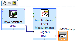
OK, I just got my CompactDAQ hooked up with two modules (9225, 9239) and am able to simple single-phase voltage (120 VAC)... I connected an indicator, and it gives me shooting random sine wave values and what I'm looking for a simple voltage reading. MAX and the DAQ assistant both work very well to the configuration task and I can see the signal in there.
I dug through the DAQmx, watched functions in the knowledge base and have searched here without any real results. I also downloaded the EPM resource kit, but it's tools for further on the road... It seems to me that this should be simple crazy, but maybe I go too hard or just looking is not in the right place? I would greatly appreciate a point in the right direction!
Thank you!
Chad
With the help of... Windows XP (SP3), LabVIEW 2009, cDAQ-9174, 9225, 9239.
Chad,
When you say "simple voltage readout" are you referring to the effective voltage of the AC signal? If Yes, you can use the Express VI 'Amplitude and level measures' to calculate the desired value.
Hope this helps, otherwise if specify you what you are looking for a little I will try again.
~ SimonH
-
Venue Pro 8: use the charger with a little more voltage and current?
I just bought a Dell came Pro 8 tablet used running Windows 8.1. The seller didn't have the original charger, so he gave me a 12W of Apple loader that had taken out nominal 5.2V and 2. 4A
Is it okay to use this charger for my Tablet? Any potential problems in the long term?
Thank you!
I'm sure that the voltage is OK to 99.9%. The extent of the current note goes, which is often misunderstood. The rated current for a charger power or power is the maximum that the charger/power is able to provide. It could be evaluated to a zillion amps, but the equipment to which it will draw only what it requires.
-
6009OEM output voltage and current
Hi all
Just try to make sense:
http://www.NI.com/PDF/products/us/20043762301101dlr.PDF
Page 3 says: high output voltage (push - pull, I = - 8.5 my) = minimum voltage 2.0 v maximum voltage = 3.5V but where can I find out what current can it provide and continue to produce an output voltage more than 4.2V? (4, 2V is the worst case for the high threshold of logic of a chip, I want to control).
Thank you!
J
Hello J,
As you mentioned is the maximum voltage of 3.5V when you have a high output voltage (push - pull, I = - 8.5 my). If you need more than 3.5V then you might need to change to an open-drain output. As you can see from the link you provided that you would receive a maximum voltage of 5V.
If you do not use an open-drain output you have to combine with a pull up resistor.
I hope this helps.
-
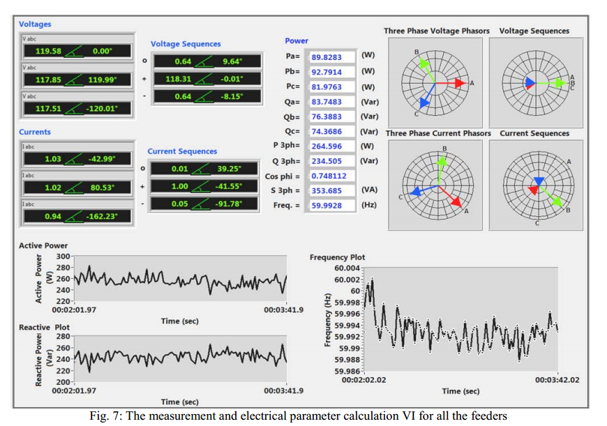
Phaser in LabVIEW for voltage and current indicator
When I read a research paper on the power system, I've seen has a reasearcher program LabVIEW (its block diagram is not shared just GUI). My question is: is-LabVIEW has a built-in function that allows to display the amount of complex in | Mag |
Greetings muahang1234
There is a suite for LabVIEW called Suite of electrical power OR LabVIEW that might interest you. Visit ni.com and evaluate the software, it may be the tool you're looking for!
Let us know how it goes. Nice day.
-
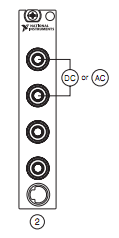
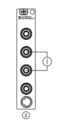
Measure the current and voltage using DMM sharing a port
I want to measure pressure several times on a pcb, where I connect the ports of digital multimeters to the card using simple cards. Switching between the different voltages is done using simple. If the black port of DMM (the second from the top photo) is connected to the Earth to give the measure correct volt.
And then I want to measure current through different lines. The problem is here. Given that two measurement types share a port, how do I get the correct voltage and current measurement? The second port of top would be grounded, so I can't use the method of measuring the voltage across the line through a resistance with a known value, since then the second port must not be connected to the ground. How can I use the current state of the DMM measurement? How measure current? Are there examples of this? Tried looking through manuals, but could not find the good starting points.
so I can't use the method of measuring the voltage across the line through a resistance with a known value, since then the second port must not be connected to the ground.
On all of my games to test I have to mux my land of the signal along with the salvation of my signals.
All my mux test sets are set up for the topology 2-wire because there is no other way to do it without the weak side of switch also.
-
How to measure high voltage (60-70 v) and current (75-80 a) using a DAQ PCI or USB DAQ
Hello
I work with a system that works on about 5kW. The output of the system voltage can go maximum up to 60-70 v and thus the corresponding current around 75-80 a. I have 10 these systems that I want to read one by one continuously for long periods.
I am designing the automated system best suited for this and looking for the best material that would be appropriate for this purpose. Looking for options, I found that an SCC - A10 attenuator may be used to get the tension down by a factor of 10. But I'm confused, if the high current will pose a problem and also how to measure this high current.
I need to measure the voltage and current at the same time. Please suggest what would be the most appropriate fitting for the same (preferably PCI or USB)
The hope of a quick response. Thanks and greetings
Reena Sharma
Facilitated learning
Reena says:
Hi all
There is good news that the idea of using a compact data acquisition has been accepted by the authorities of the society. I'll be very grateful, if you could suggest me with some hardware modules suitable for my application and how I can use them best.
Thank you very much
Reena
I was able to make a few suggestions, but do not have the time to understand your needs and the forums are not the best solution.
Your Local OR representitive actully gets paid to do this kind of thing. a google search suggests THAT LME is in Pasadena. Zack Collins would be the contact rep
-
Bug with all numbered, measures the percentages and units. Help!
Hello! Im having some struggles with '00' behind each individual measure, percentage, unity and point I use. This allso mess up to the size of things.

Does anyone know how to fix this?
Hello
We have released an WINDOWS ONLY fix today that solves this problem of corrupted preferences. Go to the creative cloud application and download the patch CC 20151.1 (19.1.1)
If you see not the patch in the creative Cloud application wait on or refresh cycle you can disconnect and connect to force refresh the list of available patches.
Kind regards
Ashutosh
On behalf of the Illustrator engineering team
-
Define independent for rpm and current control
Hello
I need assistance with labview. I am able the current, voltage and rpm of a pump connected to a control box. The control box is also connected to my DAQ. My requirement is that I would like to monitor the blood and fluctuations in current on an in labview waveform chart, once I run the file vi and monitor the number of laps when I start the pump. When I try to run the file vi before the pump starts, I get an error code "200284. I understand that the RPM in my vi counter does not receive signals and ends the program. How to set a control sparate for the display of the voltage and current regardless of whether if the pump is started or not? or how to set a control to monitor RPM display only when the pump is started and does not affect the voltage and current display part of the VI.
This may seem a bit complicated! Please give me your suggestions on how to do this!
Thank you
Rajesh
Looking at your code, the DAQ Assistant on the background is taking in the RPM data you are looking for. You can do a right click on the arrow to the left of the option "timeout (s)" at the bottom of the DAQ Assistant ExpressVI and select Create > Constant. This will create a constant within seconds that represents the DAQ Assistant time-out on entry. You can base the number on how long it will take the number of LAPS to enter to start.
.
It should look like the above, but you can change the time that the ExpressVI will wait for your needs.

Maybe you are looking for
-
How to change the Home Page of mozilla.
My home page changes in searchus.com every time, I start my browser. and when I open a new tab its shows a blank page, which has been showing some of my links that I use for most. Please help me stop the changes in the home page of the browser. and n
-
Satellite A350D - error meassage apear everytime I log and BIOS problem
I have two problems here on bios and any error message please help me... Thank you very much.. Merry Christmas... Now, every time when I ' am turn my lap top before she continue to windows there is an error message always appearing. Intel UNDI, PXE -
-
Try to install on Satellite L500 - Win7 x 64 flash cards
I recently installed Windows 7 64 bit on my mother's laptop (L500 - PSLJ0A-01E013) and download version of flash since the support site cards ([here | http://www.mytoshiba.com.au/support/computers/satellite/l500/pslj0a-01e013/download?os=25]) Transla
-
I can't download drivers for Satellite U500-1f4
Hello!I just bought a toshiba U500-1f4. But I can't download any driver on the official website of Toshiba. By clicking on the download link for any driver, I get "403-Forbidden". Any advice? Thanks in advance.
-
HP 15-g020dx: I got an error message "operating system Boot Mode changed."
I had got an error message on the boot image and I came here, telling me to change the startup parameters to the legacy that I did, but I might be able to register the change because he could do nothing except "esc", which had to cancel the change ty