myDAQ inaccurate reading of the analog signal
Hello
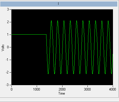
I'm usign the myDAQ in lieu of a USB6341 who is busy on another configuration. The DIF is with the USB6341 I connect two analog inputs without any noise problems, whereas with the myDAQ, I get what you see in the image as an attachment.
Now, (the white line) of a flat line but often I get all these ouliers tips coming clearly through the myDAQ.
Two different voltage on two analog input signals of the my DAQ I can see the same spikes descending in the same moments for both signals, which is another confirmation that the noise is added by the myDAQ.
Also, try different myDAQs (we have many University) does not solve the problem.
Any idea on how to solve this problem?
Thank you very much.
Giacomo
Hello, Giacomo,.
Sorry for the late reply.
Now that you mention the myDAQ DMM.
Please note that the DMM uses a different circuit (Figure 2, page 5):
http://www.NI.com/PDF/manuals/373060e.PDF
How the signal looks like with the myDAQ scope Soft Front Panel?
Although the USB-6341 has different (and better) specifications seems to be rather a noise or signal problem floating.
Can you 100% certainly confirm that you do not see this problem with the USB-6341 when you perform a differential measure?
Have you tried the method explained in Figure 7 on page 13?
Do you see a difference when doing this?
Tags: NI Products
Similar Questions
-
read the analog signal 0-10 volts of NI6123
I'm reading the analog signal of NI 6123. The range of the analog signal is 0 to 10 volts. This works well when the signal voltage is 0 to 5v (0 ~ 32767). But when the signal is 5 to 10 volts, the value read is always 32767. I also tried the different reading function: DAQmxReadBinaryI32, DAQmxReadBinaryU16, DAQmxReadBinaryU32. The value is identical to DAQmxReadBinaryI16. My OS is windows vista. Here's the part of my codes.
**************************************************************************************************************************************************************************
Create analog data tasks.
DAQmxErrChk (DAQmxCreateTask("",&datHandler));
DAQmxErrChk (DAQmxCreateAIVoltageChan(datHandler,"Dev1/ai0:7","",DAQmx_Val_Cfg_Default,-10,10,DAQmx_Val_Volts,NULL));)
DAQmxErrChk (DAQmxCfgSampClkTiming(datHandler,"",RATE,DAQmx_Val_Rising,DAQmx_Val_ContSamps,RATE*MAXLAS));
DAQmxErrChk (GetTerminalNameWithDevPrefix(datHandler,"ai/SampleClock",trigName));
Create counter tasks.
DAQmxErrChk (DAQmxCreateTask("",&ctrHandler));
DAQmxErrChk (DAQmxCreateCICountEdgesChan(ctrHandler,"Dev1/ctr1","",DAQmx_Val_Rising,0,DAQmx_Val_ExtControlled));
DAQmxErrChk (DAQmxCfgSampClkTiming(ctrHandler,trigName,RATE,DAQmx_Val_Rising,DAQmx_Val_ContSamps,RATE));
DAQmxErrChk (DAQmxRegisterEveryNSamplesEvent (datHandler, DAQmx_Val_Acquired_Into_Buffer, SPLEEN, 0, EveryNCallback, NULL));
DAQmxErrChk (DAQmxRegisterDoneEvent(datHandler,0,DoneCallback,));
Start the task.
DAQmxErrChk (DAQmxStartTask (ctrHandler));
DAQmxErrChk (DAQmxStartTask (datHandler));
In the call back function:
DAQmxErrChk (DAQmxReadBinaryI16 (datHandler, SPLEEN, 3.0, DAQmx_Val_GroupByChannel, data.laser, MISS * MAXLAS, & (data.dataRead), NULL));
DAQmxErrChk (DAQmxReadCounterU32 (ctrHandler, SPLEEN, 3.0, data.counter, SPLEEN, & (data.ctrRead), NULL));
write data to the file.
data.cfile.Write (data.counter, sizeof (int32) * RATE);
data.cfile.Write (data.laser, sizeof (int16) * RATE * MAXLAS);
**************************************************************************************************************************************************************************
Thanks in advance
To make sure that your device is working properly, I recommend first to test the entry in measurement and Automation Explorer (MAX) analog. You can test your device by right clicking on it in the configuration tree and selecting test panels. See if you acquired signal 0 - 10V as you expect. The next step would be to try one of the sample programs that perform a task of analog input. These examples can be found in the start menu > programs > National Instruments > NOR-DAQ > text based code supported. Try an example that does an analog input continues and double bed (instead of binary data not adjusted).
Your program looks good at first so I found nothing that stood out. However, one thing to check is if your function generator (or signal source) expects a 50 ohm or high impedance. This could cause reflections of the signal and cause the device to possibly read a voltage of half of the desired value.
-
reading of the analog inputs with RPC
Hello
Because LabVIEW can not handle this (in VI; the value that you have saved the excel file has not been the same, that I saw during the measurement...) This confused me for a long time
 ), I want to write a C++ program (IDE: Dev - C++) which can read & record 2 analog inputs of the NI USB-6009 box. For this, I looked for an example of National Instruments and I found a little. But my problem is that I can't even use any example, because it has always held a mistake, after that I have compiled and started.
The error once the task has been created and has the :-200220 error number with the description "device identifier is invalid. But I do think that its invalid, because it's the xP example
I must say that I am new in programming C++, which means I could have a rookie mistake. And I couldn't find documentation or something for the NOR-DAQmx library.
Someone has similar problems with DAQmx and C++ and know how to fix? I don't really know what I can do now without a working example or documentations...
Hi Mario
It's the same thing. You didn't just save all of the data:
Please take a look at my comments in the attached VI.
Christian
-
Hello
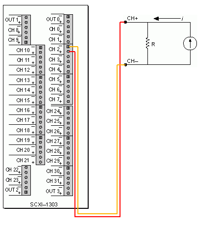
I'm trying to use two sensors of moisture Omega HX85BA and experience two CFI mass flowmeters in current loop. Humidity sensors have three outputs 0 - 10V, while flow meters have two outputs 4-20 Ma. Can I have all four sensors to wire to the same block of connection SCXI-1303 and read all the signals in the same VI? the block is connected to an SCXI 1102 b card and a 6052E DAQ of NI PCI card.
Thanks in advance!
Hello BBalmforth,
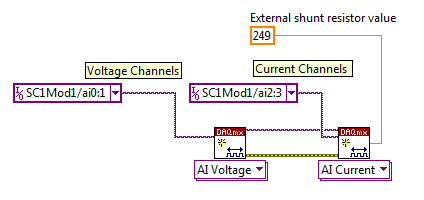
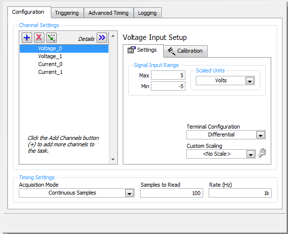
Yes it can. Although you will need external resistances (I recommend resistors precision for better accuracy) for current signals. The SCXI 1102 b is indirectly measuring the current by measuring the voltage drop across the resistance. The table below describes the current diagram and how it will seek in LabVIEW and DAQ assistant.
Wiring diagram
LabVIEW
DAQ Assistant
Kind regards
Izzy O.
Technical sales engineer
National Instruments
NI.com/support
-
Good day to all,
I use NEITHER-7350, LAbview 8.5 and try to measure the voltage from a power source.
Is there a screw that read the analog inputs. I can't open the examples.
Thank you
Have you watched the DAQmx? Create a virtual channel, start the task and read the value.
http://zone.NI.com/DevZone/CDA/tut/p/ID/5370
-
I just installed a diamond ATI TV Wonder HD 750 PCIe on my 64 bit Windows 7 system (it's actually the second tuner card I tried) and still get the same problem. Media Center recognizes the card and both tuners analog and digital, but fails the analogue listening. I get digital very well. I tried to add a channel manually and still no luck. I use cable TV with no cable box and tested the signal on my TV and receive all channels.
I also downloaded the latest Diamond driver and installed all updates more recent windows.
In Media Center, I tried to automaticlly and manually select my signal and each combination, but available with no luck.
Can you please help
Rob
Out of curiosity, what was the 'other tuner"which has been tried before?
Honestly, my recommendation would be to return the tuner (if possible) and get a combo tuner or hybrid that is known to work properly. My first recommendation would be for a Hauppauge HVR-2250 (Council dual combo/hybrid), because it works wonderfully in MC as a tuner NTSC/Clear-QAM of combo/hybrid. MC knows how to treat as what it is, and it works very, very well (I have not one.)
That, or an AverTV Combo G2 (which is not as flexible as the ' 2250, where its slightly lower price.)
HTH,
ChrisMS - MVP (Media Center) [If this post can help solve your problem, please click the 'Mark as answer' or 'Useful' at the top of this message.] [Marking a post as answer, or relatively useful, you help others find the answer more quickly.]
-
reading of the analog inputs of tension about a 5% error PCI 6259 of gain
A possible solution could be to read data not adjusted with the driver of comedi and apply your own scaling in software. You can see my post here showing how to get the coefficients of calibration of your DAQ with DAQmx hardware.
I agree with Andrew that the offset of 5% is very suspect, given that it is the amount above the nominal range DAQmx cards actually given to the.
-John
-
generation of digital, analog signals read snap SMU-6358
I have two SMU-6358 card and I want to send control signals to my camera and read the analog signals from the device with them.
For the digital control signals, I tried to set up a system where I specify the identifiers of the pins, bring them into arrays of strings - the respective waveforms would be collected in the tables too - and I transfer them to a VI of inputs/outputs multiples that puts digital waveforms for the cards output pins.
I developed this code here, but it doesn't seem to work. I can't understand how I can convert the string and form table wave to meet the requirements of the input/output VI or which another VI I could use to do the job. Or is there a smarter way to do it?
Thank you
Kriváň
Dear Kriváň
Please find attached the VI in LV 8.6 format. Also, I HIGHLY recommend to rearrange the front panel and which makes it neater, your code is very hard to read and not structured at all. I hope this helps!
-
Generation of the trigger (or TTL) analog signal
Hello world
Well I look at the droplet, riding on the vibrating bath. In this case I have to synchronize the device with the accelerometers.
Accelerometers are connected to the vibrating plate vibrating sinusoidal with frequency of 80 Hz. I am the acquisition of acceleration using NOR-DAQ USB 6212. A camera (Camera Link Basler, NI PCIe-1433) is used to acquire images of the vibrating plate. The frame rate of the camera is 20 Hz which controlled by external signal (TTL) or camera attributes.
I would like to generate a trigger of data acquisition (signal HAVE) to the camera at the first minimum acceleration in the attachment. I've also attached the file vi. Could if it you please let me know if is there anyway we can generate the trigger of the analog signal.
See you soon
NGO
Hello, NGO,
Can you post the update VI?
-
How to read the analog inputs of one Board of R for (PXI-7851R) series
You can guide me please with the steps for reading of the analog inputs of a series a. card I use as the target fpga PXI-7851R.
Have you looked at the examples provided with LabVIEW? There are examples showing how to read the analog inputs.
-
The data read into the buffer HAVE lack samples at the beginning
I use a box USB-6251. The program implements two channels of AI (read I and Q) on a single task and one channel on another task. The channel uses the ai\SampleClock as its clock, so that both are synchronized. C creates a digital pulse periodic rising edge (a clock basically) which is used as a trigger on an external function generator. The signal from the unit after going through some material, external signal processing is ultimately what is read by the channel of GOT it.
We know from the relevant signals, they seem to be correctly synchronized scope. IE, the analog signal to read arrived on the channel of the AI of the acquisition of data more or less instananeously when the trigger is activated. If there is a delay, it is of the order of microseconds.
However, when I read in the buffer of HAVE (repeated FiniteSamples), waveform, I always come back has a section of samples at the beginning that seem to be returned of the first actually read data-point (see attached image). This delay is of the order of milliseconds (it varies with each series).
I want to totally eliminate this delay. The signal should be a sinusoid which begins to sample 0 and is continuous through until the last sample read.
I put the code below.
Installation program:
Create analog read the task
analogReadTask = new Task ("analogReadTask");Create the virtual channel for the component I
analogReadTask.AIChannels.CreateVoltageChannel (initParams.AddrI.ChannelAddress, 'I', AITerminalConfiguration.Differential,-4, 4, AIVoltageUnits.Volts);Create the virtual channel for the Q component
analogReadTask.AIChannels.CreateVoltageChannel (initParams.AddrQ.ChannelAddress, 'Q', AITerminalConfiguration.Differential,-4, 4, AIVoltageUnits.Volts);To set the clock for the analog readings
analogReadTask.Timing.ConfigureSampleClock (string. Empty, initParams.SamplingRateHz, SampleClockActiveEdge.Rising, SampleQuantityMode.FiniteSamples, Totalechantillons);Create the mult-channel drive
analogReader = new AnalogMultiChannelReader (analogReadTask.Stream);
analogReader.SynchronizeCallbacks = false;pulseWriterTask = new Task ("pulseWriterTask");
Creating a digital output channel that provides the trigger to the U/S system
pulseWriterTask.DOChannels.CreateChannel (initParams.AddrUsTrigger.PortLineAddress, "US trigger", ChannelLineGrouping.OneChannelForEachLine ");
pulseWriterTask.Timing.ConfigureSampleClock ("/ SampleClock/AI/Dev1", initParams.SamplingRateHz, SampleClockActiveEdge.Rising, SampleQuantityMode.ContinuousSamples, samplesPerPulse);
pulseWriterTask.Stream.Buffer.OutputBufferSize = samplesPerPulse;
pulseWriterTask.Stream.WriteRegenerationMode = WriteRegenerationMode.AllowRegeneration;pulseWriter = new DigitalSingleChannelWriter (pulseWriterTask.Stream);
pulseWaveform = new DigitalWaveform (samplesPerPulse, 1, DigitalState.ForceDown);
pulseWaveform.Signals [0]. The States [0] = DigitalState.ForceUp;analogReadTask.Control (TaskAction.Verify);
pulseWriterTask.Control (TaskAction.Verify);
From reading:
analogReadTask.Start ();
Start writing the digital pulse, however it will not start
until the AI/SampleClock begins, so implicitly synchronizing the two tasks
pulseWriter.WriteWaveform (pulseWaveform, true);analogReader.BeginReadWaveform (Totalechantillons, readerCallback, analogReadTask);
Result (should be a sinusoid from end to end)
Always seems to solve these problems, shortly after their validation.
The problem has start the digital task AFTER the analog task. In the small delay between the two lines of code running, read analog had already begun, and so some of the impulses of the AI/SampleClock were missed by the task. The order of departure between the two tasks of switching solves the problem.
-
How can I use my PXI-6115 meter analog signal trigger to generate pulses of frequency
I work on a PXI-6115 DAQ card and want to using the analog signal to trigger the counter it's generating frequency pulses. The manual says the analog trigger is supported, but I can't use an analog signal to trigger the start of work, in the test, I use the counter 0 to generate pulses and use the signal input port analog trigger PFI 0, can someone tell me what it is? My test VI. & error message appears in the attachment.
Best regards
If you read the error you can see digital triggers are the available trigger only when you use the output of the counter.
You can work around this by setting up a dummy analog input task which will trigger an internal digital triggering when he sees the right analog trigger.
See this thread for more details:
-
NEITHER 6052e: can I re - route the analog output of DAQ for PFI?
Hello
Does anyone know if it is possible to route analog output to one of the PFI (e.g. PFI0)? I use NEITHER 6052e and I would do the following: 1) output a signal to DAQ0; 2) then a few hundred milliseconds a signal of DAQ1; and then 3) read out a simple analog pulse on any output connector external to trigger an external device.
Thank you very much for your help!
Hello sometimes.
Could you please provide more information about your hardware configuration:
What devices are DAQ0 and DAQ1?
Are you using a PXI and PCI 6052?
When you say AO reroute to PFI do you mean you're trying to wire AO into a PFI line for release purposes or are you trying to exit and the analog signal of a PFI line?
-
Open a synchronized session of the analog inputs and position
I want to read 8 analog inputs (only three IA in the capture of code) with a PCI-6221 card at a rate of 100 samples/s, reading 10 samples/iteration. At the same time, I want to read the position synchronized with the analog inputs. Is this possible? If I just merge the position with the analog signal I get 10 readings of position for each 100 analog input readings (see chart - Red's position). For the control of the movement, I use the pci-7342 with UMI-7764 interfaces. Could someone help me out here please?
Not necessarily. As said, speeds of up to 200 Hz should work fine with a 7342. If this is not enough, of course a 7350 could be used, but there is also a completely different approach that should work with your current hardware:
7342, you may also route the phases of encoder to the pins of the RTSI. You can use a counter on the 6221 to measure the position of your axis based on the singlas you have routed the RTSI pins. Now you can use "Measure of Position buffered" (see DAQ examples) to measure the position with the same source of synchronization than your analog signals.
I hope this helps,
Jochen
-
Import MATLAB generated the file ascii in the Analog Waveform Editor
Hi all
I tried to create signals by the Analog Waveform Editor. I have some Waveform generated from MATLAB and recorded as ASCII files, following the instructions on this Web page OR, but it did not work properly. For example, if I produce a column to fill with 0.5 and import the file into the analog signal generator, all I get is a huge series of random number. I missed a few steps in the import of the waveform?
Thank you!!
Just for your reference, I could almost in half the size of your file just by saving as .hws. Also to answer your last point, you may have issues opening / importing your .txt file because it may have been opened in another program at the same time. Make sure that you have closed it in Notepad or Excel or other programs which may still be locking on the reference.
Kind regards
Jason L.

Maybe you are looking for
-
Apple TV (9.2.1) removes the internet connection when you try to use Siri
Greetings, I think I saw network related issues with my Apple TV. Everything works fine most of the time. But sometimes, including, but not limited to, when I try to use Siri, Apple TV almost always drops the wireless internet connection. I've includ
-
Why can I not see my character... I don't see a very small part in the upper part of the screen
After, I selected and installed my character... I only see a tiny part of it in the upper part of the screen
-
Camileo x 400-buzz using desktop microphone and AC at the same time
We bought this camera because it gives us the possibility of using a desktop microphone when we record interviews. It works very well if the camera uses its batteries, but when you plug in the AC, the sound recording is affected. A buzz is saved all
-
How to set up excel column width
I use the ExcelRpt_SetCellRangeAttribute function to set the width of a cell in excel. What vale I should switch to set the width for example 50, I tried to transmit values, but his does not work. After passing the values'm specifying the column cont
-
Windows Update blocks the wi - fi connection
So I bought a computer brand new with windows 7, bought a new card network wireless (Netgear WNA1000) downloaded the most recent available windows compatible 7 discs on a friends computer and hey! I can connect. I turned off my computer after the win