MyRIO FPGA read framework signals SENT
Hello community,
I now have a myRIO with Labview 2013. I try to read a digital signal to a sensor on the port DIO0 (C-Port). It works very well. The problem is that I don't know how to find the start (the SYNC nibble) of the frame SENT - and how it works with the ticks of the clock / time clock of the FPGA (40 Mhz) system. I do not understand the meaning of the clock. ticks of the clock.
The next problem is to measure the time between a front down to falling edge. In fact I can detect every falling edge of the signal SENT but I cannot measure the actual time between them. How can I measure the real time based on the system FPGA clock time? The nibble of SYNCHRONIZATION were all 56 time graduations. But how long are 56 ticks?
Best regards
Basti
Hello, Alexander.
Thank you. It works very well.
Now my problems are solved. The main problem was to build something that is capable of converting 56 ticks of the SYNC signal SENT for correct ticks of the sampled signal. The two frequencies, the Signal SENT (333kHz) and the sampled signal (40 Mhz) are different, so I divided the frequency of the signal sampled frequency of the Signal SENT - (factor of about 120). Now I can convert 56 ticks to correct the number of ticks of the sampled signal and I can find the SYNC - Puls in FEEL. The result of 56 times the factor of 120 ticks is 6720 ticks. So, I convert ticks to the correct frequency.
Thank you very much for your help!
Best regards
Sebastian
Tags: NI Products
Similar Questions
-
FPGA read/write does not not in cRIO-9073
Hello.
I'm stuck with a problem in the use of the FPGA Read/Write control please suggest a solution.
I use cRIO 9073 and I'm trying to place an order ON / OFF of GUI-> RT-> FPGA host. I use a shared variable of the network to transmit the control GUI form to host RT and I use read/write control to FPGA. I also put a Boolean flag in the FPGA VI to control if the control is transferred to the FPGA.
When I toggle the button in the GUI, I see the same change in the host of RT (shown as 16 probe in attachment 1). However the FPGA indicator (indicated as probe 19) remains the default false state. The FPGA VI is on attachment 2.
Thank you
Guilhem
Your FPGA only reads the control once before entering the loop. If you want to read control permanently, you must put it inside the loop.
-
How to read a signal of temperature continuous of a pyrometer via RS - 232
I am currently reading and chart of a pyrometer Pyrofiber Lab that arrives via an RS - 232, a continuous signal cable. As much as I know there is no device driver for this instrument (or any other pyrometers).
If I the pyrometer measures alone I can get these in LabView using the Assistant Instrument i/o, but only as a string reading ABC ' 'value emmisivity' "" "corrected for the temperature" "and not as individual numbers or data that I can use/chart. If I have the pyrometer in high mode baud rate (which is the mode in which I need), I can't read the signal at all. How can I get LabView to read continuous (and save or graphic) of the input signal? And is it possible to analyze the signal when it comes as a string with ""time""emissivity""temperature""fixed temperature "?
I am very new to LabView (and programming in general), so that advice on a good place to start would be appreciated.
You should start by reading the manual of programming. Instruments of series such as this one are unique in how the communication interface is implemented it is quite difficult to give any kind of specific help. I suggest that you start to read/control from a program of emulation of terminal as Hypertermina, Procomm, etc before attempting to write code. Then, you can view examples of shipping communication series to see how you could write the program. Personally, I have never used the Instrument i/o Assistant.
p.s. attaching the manual would go a long way to get more help.
-
Frequency of calls to control for the FPGA read/write
Hello
I use a cRIO-9076 with a module NI 9476 DO spend some faucets. It is sometimes necessary for faucets with a pulse time down to a few ms of impulse.
The FPGA VI Gets the power tap queries, executes a logic of security, and routes the numerical results for the exits. It gets applications power of the VI on RT target that uses the function ' Read/write FPGA control' interaction programming of the FPGA VI front. The loop on the RT runs with 1 kHz, no iteration is missed. That means, it should be possible to switch the valves with a resolution of 1 ms.
What I see on an oscilloscope, is that the output digital are high for multiples of 50 ms, the system does not reach the valve for example 80 ms pulse or pulses shorter than Ms. 50 is a kind of limitation for calls of "FPGA read/write control"? I tried both options for arbitration, but it does not help.
The best knowledge of the limiting cRIO/module/features or ideas? Thank you in advance.
Karsten
Hi Karsten
You use any time in your FPGA VI?
It is useful to your code by sending as an attachment so that I can have a look.
Kind regards
-
Unable to read the videos sent to email
original title: videos
Why can't open and read a video sent to my email address?
Why can't open and read a video sent to my email address?
===================================
You know the video format (extension)?You may need to change your file associations for this format
or you might need a codec or even a reader of different media.Also, you may need to convert h into a compatible format.
-
Effective use of the FPGA read/write
I am writing an application for a CompactRIO real-time and I am looking for ways to simplify my code and reduce the CPU usage. I use FPGA to do much CAN e-mail and signal processing, then I have a VI running on the real-time processor that reads values in the FPGA, does some processing and outputs data in the FPGA. My code running on real-time parallel uses several loops running in a master/slave architecture. A single loop reads all necessary information in the FPGA in indicators and writes the values of the controls in the FPGA. The other loops read entries and manipulate the outputs via local variables.
My question if it would be more effective to get rid of the loop which is dedicated to the communication of FPGA and has of each loop to read and write directly on the FPGA. If I use a reference block FPGA open and use the reference of the output in several loops, each read/write operation block others until it's over? Each output is changed only in one place in the code, but there are several entries that are used by multiple loops. It is even more effective for each loop of read/write for the FPGA on request? How will this affect determinism?
Thank you
Jon
Jon,
Read/write controls is not deterministic, but I think that your previous method should work just fine, as long as you have that unique writers. If you have multiple writers, you start affected by race conditions.
I don't think you will see a significant improvement in the performance/CPU in the alternative method. You would see big performance gains if your master loop reads more slowly indeed, but it's always a compromise.
-
the 1900 myRIO FPGA multi channel data acquisition
Hello world
I would ask you for help in my program acquisition and generation of data. The main task of this program is to measure 4-channel adjustable sampling rate (2 kHz and less) and to generate an analogue signal in up to 50 kHz sampling frequency.
I created two loops and everyone is dedicated to different operation. The first loop is to measure data, or in writing to the DMA FIFO and the second loop is dedicated to the generation of signals. I adjust the main parametrs of the two loops in a host of vi.
But what is my problem. I compile the program in the FPGA of myRIO without any problems and I can run too but the problem is that sometimes, especially when I adjust the lower sampling frequency of the loop to measure to the rank of channel changes measured and I see that the signal that is connected to osciloskop AI0 channel on channel AI3. When I stop the program, set the higger sampling frequency and run it again, it works well and the signal is on the right channel. Could someone help me with this problem? I tried to check all the forums that I know, but I did find an article or a discussion of a similar problem.
Thanks a lot... :-)
Andrew,
I just solved the problem. I thought about it again and I got the idea to change the size of the DMA buffer on the side of myRIO. I expanded the buffer of 1023 elements in 2047 and it works well and I can change the sampling without problems.
-
Why visa read reads most bytes sent
Hello
I use visa read and write to communicate with the device via RS232. I sent several string commands.i just use serial communication of basic to read and write the commands.my total length of string is about 6626. I also used the size of buffer of about 7000. When I send the string to write Visa, I'll get a number (byte) output 6626 sometimes and sometimes less than that. I also used the property node for the bytes to port I used the number of bytes to read visa. But as number of output here, I get a lot more like over 6670 and sometimes less than 4000and 6620 and sometimes only some and 5000 and some.it doesnot remains constant. How can I solve this problem? why I get more bytes that I sent as exit visa read? and sometimes less? And sometimes more visa write number of output?
waiting for help.thank you.Tadhika,
-
FPGA: the internal signals in ModelSim display
I have a piece of code written LabVIEW FPGA in that I am trying to simulate in ModelSim. I followed the instructions in this link, but the example is a simple incrementer with no internal signal (only the input and output).
I created a test bench and started the simulation, but the macro provided .do only adds the entries and exits to the wave window. ModelSIM lists pages and pages of processes and signals that can be added to the waveform window; all have names completely opaque. I found something called 'TheWindow', and then a subdirectory called "Thatcher" and added all these signals to the waveform window. The names are things like ResHolder00000000000001 and provide no information on where they came from.
I tried to assign labels to the sons of my LabVIEW diagram, but that did not help at all in creating useful names. I need to check the progress of States in my VI but can't find anything that seems like the appropriate signal. A lot of available under 'Thatcher' waveforms are waveforms static, uninitialized, or both. How can I assign names to internal signals so that the waveforms are actually intelligible?
On a side note, it is also a problem in the synthesizer. I'm used to using the synthesizer output to 'pre-debug"my code, but LabVIEW seems to ignore the process of inference any macro. I tried to put a SCTL with an incrementer and LabVIEW does not infer a counter. I have never seen one of my machines of State recognized in the synthesizer, even if the code works correctly.
Using ModelSim PE 10.3, I understand is not "officially supported", but the fact that the synthesizer and the Simulator have the same denomination made problem wants me eliminate this as a problem. I do not use one of the PE extensions on the version SE.
Hi Nick,
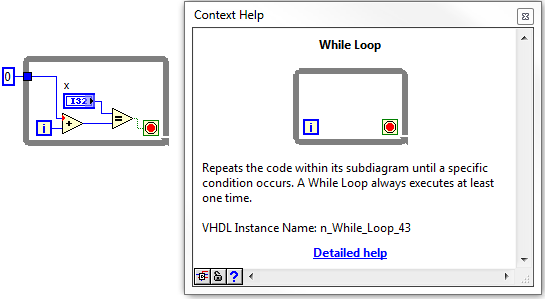
If it is not the most readable, its not too hard to find signals that you are looking for. Your biggest help will be context-sensitive help in LabVIEW. If you hover over the structures, nodes, or son, in your LabVIEW FPGA design, at the bottom of the help context window, you'll see what we call the 'name of the VHDL Instance".
Once you navigate through the hierarchy down through the window, in the VI, you should start to see some of your top-level objects, such as while loops etc. From there, you can navigate down in whatever the level and find the wire you are looking for.
I did not have the ModelSIM on my machine, but it works for the ISIM. I wish they had a search function, so you can just type in the signal you are looking for.
-
Someone at - it an example of LabVIEW for I2C communication to read/write an eeprom?
I use sbRIO-9636 with FPGA.
I already tried with the "Advanced I2C" example, but it works...
Can someone help me?
Another suggestion:
You know about the VI package manager? There, you can install an application open source I2C & SPI API (worms. 3.0.0.22). It is an easy way to implement a system of Bus I2C on an FPGA target.
In this way is a little bit smarter.
Maybe you like it.
-
In the target FPGA read/write control function?
Hi people,
I learn a lot from the sample project FPGA, including how you can easily retrieve and set controls and indicators in an FPGA using the read/write control function running in an RT target.
However, I can't find a way to do something similar in a FPGA target. I've been down this road before - that is, trying to move the data in/out a looping VI FPGA (void) to a (parent) FPGA VI - where my memory points to reach what I needed use.
So I was happy to see the palette FPGA enabled me to drop the control functions to read/write on a FPGA vi target. But alas there where tons of errors (not compatible son for target, etc.) and I guess now it's not possible.
So, just to be sure, I'm not missing something, is there something like control functions to read/write to use in an FPGA for read/write in an another FPGA (looped)?
In addition, why would I be able to read/write on a FPGA vi control functions if they are not supported? (Sorry for the n00b question)
Thank you
Steve
maherhome wrote:
You're right that I don't have this knot in my palette. However, I also do not seem to have a Refnum Occurrence in the palette is in the FPGA (see below), but I need to synchronize several loops of FPGA and added research using the textfield in the VI editor (and if compiles and runs). So 6 months to Labview and I'm fuzzy on how the palette is restricted
I don't know what you're trying to prove here. There is no control of refnum in search in your image. Occurrences are available in FPGA, and for control of refnum for one you just right click on a function of the instance and create a control. If you can create a valid thread of a certain type of data, then you can create a control or the indicator for it, regardless of the question to know if this type of control or indicator appears in the palettes. However, the functions that you can use in the block diagram are limited by what is available in the palettes.
maherhome wrote:
Regarding orders read/write for the FPGA/lights, I'm surprised that the infrastructure developed to allow read/write between RT and FPGA has not mobilized to allow read/write between FPGA and FPGA. The elements of memory function, but they are less convenient.
You may have noticed that you cannot compile the individual parts of an FPGA VI and combine them later; This is because when you compile an FPGA VI, all its subVIs are essentially merged to create a single block diagram (with additional logic if one not reentrant Subvi is used in multiple locations, this is why it is not recommended on FPGA). The subVIs no longer exist in the FPGA compiled; reading and writing a control on them would make no sense. If you want similar behavior, use global variables - but understand that global variables store values in FPGA logic resources. Using the elements of memory (or FIFO, which can also store in memory) leaves more fabric available FPGA logic by storing data in resources specially designed for this purpose.
-
Hello
NEITHER uses the framework of education for almost all their FPGA designs today. I would like to get a deeper understanding of it and start using it in my own creations. However, I have not found all the resources that describes what classes should I create on my own, which classes they must inherit, what methods need to be overridden etc.
Are there guides development of framework of Instruction or tutorials somewhere?
Best regards
Anders
-
How to read digital signals with pre-and post-trigger on a card PCI-6251
I have 22-bit parallel position of data entering TTL lines to 16 kHz with a pulse of marker that says when the data is valid. I also have a fault line which gives an impulse when an error condition is met. I want to read in the 22 lines of position with 500 positions of pre-event and post-event 500 data when the fault line says. How do I pre and post-déclencher lines digital input on a card PCI-6251?
If this is not possible on this map, which maps PCI would be possible?
-
read the signals of pressure using signalExpress
Hi, I have no pressure option under DAQMx Acquire-> Analog Input
menu when I add a step to acquire pressure signals in SignalExpress 4.0.
Everyone knows what additional module I need to do? Thank you. Cong.You may need to upgrade your version of DAQmx. The type of pressure measurement was added in DAQmx 9.1.
Here is a link to our latest DAQmx, 9.3:
-
Here is my sensor
Pressure sensorHere's the DAQ data sheet:
Here are my issues:
First of all I don't know what is LO and HI exactly in the DAQ 9219 material.
Second, I don't know what pin code I should connect the DAQ sensor signal wire. PIN 4 or 5 pin? The sensor has three pins, and I guess I should connect the other two wires to the power supply.
Thirdly how to calibrate the sensor. In labview choose voltage in the wizard?I'm pretty new in this acquisition of data and I need your help.
Thank you
Hi SilasIII,
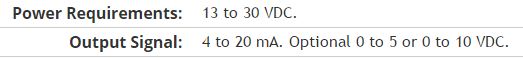
Hmm well 3 sons are probably on the ground, the power and the return signal. The datasheet for the sensor says:
First of all, you need to know which model you have (4-20mA, 0 - 5V or 0-10VDC). HI refers to the return signal, LO essentially means the land of the food that feeds the sensor. Then, you must get the 13-30 VDC supply. I don't think this should be too complicated and can be a simple wall DC power. You can learn how to create a custom in DAQmx scale. I hope that this is a starting point.
Kind regards
Eric
Maybe you are looking for
-
How do I uninstall Awesome screenshots for Firefox
I installed Awesome screenshots for Firefox. How to uninstall it?
-
All the pop popup in new tabs instead of new windows.
All the pop popup in new tabs instead of new windows. I don't know why, but this happens not just a site, but all of them.
-
Update of Windows 8, incompatible usb drivers?
I use a HP Pavilion dv6-7029tx running windows 7 Home premium 64-bit Im trying to upgrade to windows 8 Pro and depending on the upgrade wizard the following programs is not compatible and must be uninstalled. * Intel (R) USB 3.0 eXtensible Host Contr
-
recovery of sistem lost factory for windows vista in the other partition on my drive
well after I have reload the sistem recovery those partttion on the hard drive that have already charged recovery is now missing. How can I reinstall the CD it again?. cause I have the factory CD 4. Thank you
-
My HP C5280 printer only prints part of photo
Original title: Mr My HP C5280 printer only prints part of photo