NEITHER 9234 fifo dma file samples
Hello
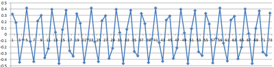
I have a problem when sampling using the cRIO and map AI NI 9234, currently configured to sample a signal of Hz 1 k of the side signal generator FPGA goes directly to the DMA which is (1023 elements in size) on the side of the host (size of the element 1 million). With the help of the producer, architecture of consumption and saving on PDM on the consumer side. The producer has read dma fifo. Please see pictures any help would be great!
If I plot the data, I get this:
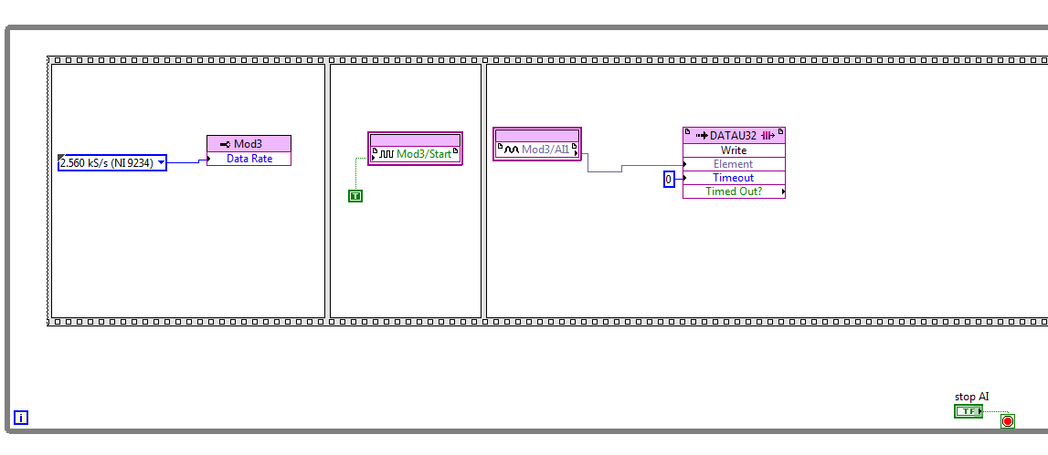
Here is my code FPGA:
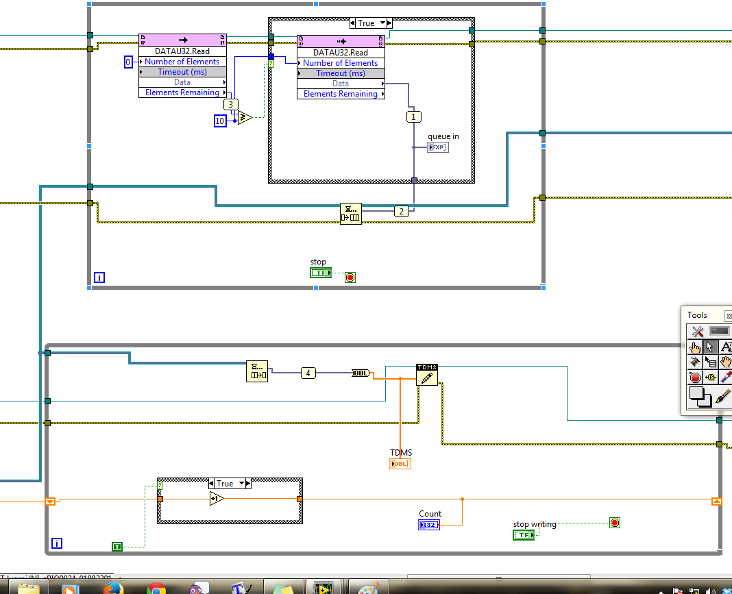
Here is my version of the host:
Hello
The problem has been resolved on this post.
Thank you
Tags: NI Software
Similar Questions
-
Hi all
I'm under LabView 2013 and have updated all drivers and versions on my local computer and also on the Single Board RIO 9636 I use. My goal is to measure 4 similar entries corresponding to four different microphones and then each individual signal as an output wave form. I try this using the FIFO DMA 4.
The problem that I am running is that I am not able to read data from the RT Microprocesssor VI using the FIFO 4. Reading methods. I'm relatively new to using a FPGA and labVIEW programming. I attach two diagrams for information purposes. I thank in advance for any help, you may be able to provide.
mcoe12 wrote:
What happens is that data from the FIFO are just 1 and the real are not the case of the incoming data.
AH! If you said that in the first place, I have identified the problem in the first post. It seems that your data types do not match - fixed point for the FIFO DMA configuration does not match data from the analog input. That's what the small red "points of coercion" you are showing on writing of FIFO. My guess is that's why data is not properly through.
While you edit digital representations, also change the sampling frequency is an integer, to match the input of the timer.
-
Accuracy of size for the FIFO DMA
I started to develop a code of RT for cRIO with DMA FIFO function application. A few questions have very fundemental
fluctuated around in my mind. The FIFO DMA is supposed to be made up of two components FPGA)
side & on the RT side).
1 the total THAT FIFO composed of FPGA side FIFO + RT side FIFO?
2. the FIFO of DMA size that I put inside the FPGA target in the Project Explorer refers to what just FPGA)
FIFO or Total size)? If it's just FPGA side FIFO, how big is the RT side FIFO together (is
It automatically assigned by RTOS free memory function)?
3. in addition, size defined programmatically by using DMA-configure is the equivalent of setting the size
in the Project Explorer?
4. Finally, how can I estimate the maximum size of the FIFO that I am allowed to use?
Thanks in advance for any response.
Hi Shiva419,
1. Yes, at least a DMA FIFO has these two sides
2. I just read in another reply that the size you set for the FIFO in the Project Explorer is the size of the FIFO on the side FPGA. The size of the FPGA on the side of the RT is much larger (default is 10000 items).
http://forums.NI.com/NI/board/message?board.ID=280&message.ID=5108&query.ID=99697#M5108
Mandar-
-
Hi al, it's a long!
I noticed a strange behaviour when I read from a FIFO DMA between FPGA and RT host on my crio (9014 controller and 9104 bottom of basket). The FPGA is writing data to the FIFO 2 points every millisecond and the loop of the RT is the reading of 500 data points each loop of the MS 250 CR period is controlled using the hold until the next ms multiple function.
Wait until the next use means ms that during the first round, the wait will be not so I gave the FIFO DMA read method a timeout of 750ms to allow data points to accumulate on this first iteration.
I then ran the VI and it read the data as planned and it was always 0 in the FIFO. Then using the system monitor, I noticed the CPU usage on the RIO and was surprised to see that it was 30%
 !
!After a lot of puzzle and many other attempts as to set the timeout to zero if delays fair read until here, I've decided are enough data points and then executes a little behind so that there is always a constant number (non-zero) of data points in the FIFO. Now, the VI runs and only use about 3% CPU.
I thought that in the first case as I read exactly the number of points in the FIFO that I was tripping some kind of voting behavior in the playback feature which has been hogging the cpu.
So I ran a business with a zero time-out, where I was reading with 0 points of data to the left in the FIFO as in the first case and waited to see if the delay of read but it never does and the CPU usage is normal.
So what's happening? I'm puzzled!
Thank you
Steve.
Hi Steve,.
I think I can explain the use processor behavior that you are experiencing:
Case 1: Loop with nonzero time-out
-Your code starts with wait a multiple ms: This means that a 0-250 ms timeout occurs (on average 125 ms)
-Then your code tries to read 500 data points in the DMA FIFO (if 500 points come in every 250 ms). All data cannot be presented yet.
-If 500 points are not yet ready, polling occurs until they are. During the time of the poll, the CPU usage is high. Finally, the data is read.
-The next iteration of the loop begins.
-The code is now expected up to 250 ms after the last function call until the next ms Multiple. Roughly the same amount of data should be available by the end of this expectation as in the last iteration. Therefore, the question about the next FIFO DMA read should be roughly the same, and the CPU usage will remain high.
Case 2: Loop with zero time-out
-In your code, immediately after the first call to wait until the next multiple ms, you "synchronize" by reading all the remaining data from the FIFO.
-In the next iteration of the loop, we can expect the call until the next ms Multiple wait the entire 250 m means that the data DMA FIFO (discount jitter) should be ready. If jitter is low enough, this will result in delays very little of the read DMA FIFO and a low CPU usage.
I would recommend either using a timed loop and read the exact number of data points available (if your application can handle variable size data sets), or using a while loop as you are and make sure that the loop priorities are defined such that the CPU usage high does not affect critical functionality.
Thank you for the very good question; I personally really like thinking through these issues! Please let me know if you have any questions that deserve further discussion and have a nice day!
Kind regards
Casey Weltzin
Product Manager, LabVIEW Real-time
National Instruments
-
NEITHER 9234: sampling rate: cRIO, FPGA
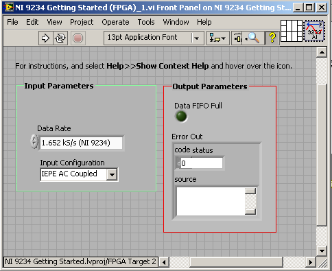
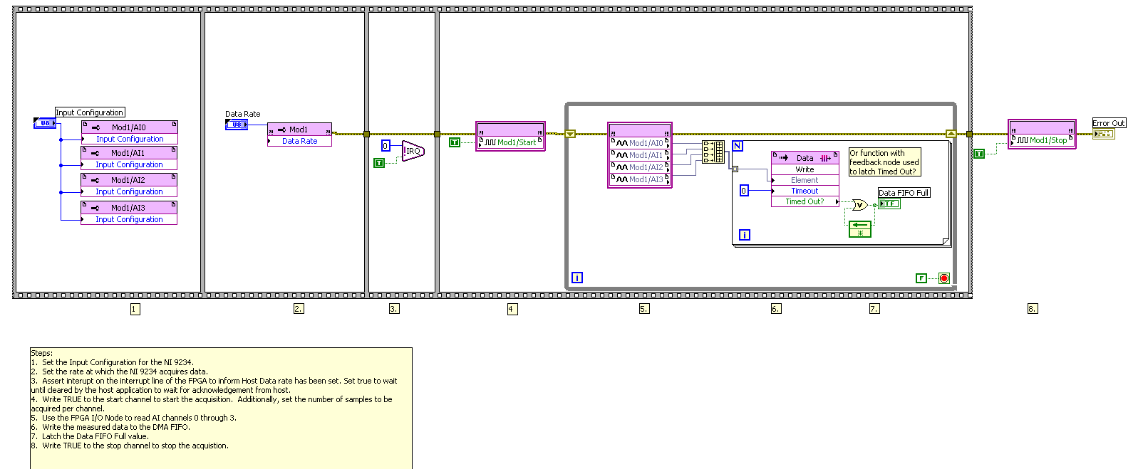
For the NI 9234 module, before Panel block diagram of my my cRIO FPGA code is as below.
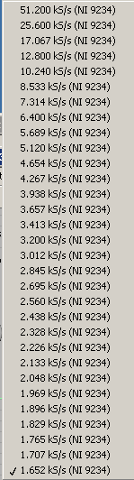
The sampling rate (speed) is selectable between certain values as shown below.
You have an idea how I can do the sample with a lower rate that is smaller than the option of character (1.652 ksps / s)?
Hi Cashany,
Take a look at this link. Page 16 describes the limitation that you run in. The main time base are divided essentially only toward down to some data because of the way the camera rates physically handles analog and digital filitering. So it's not really a way to divide the beyond that point.
-
Maximum sampling frequency for the NI 9234 is given as 51.2 kech. / s in documentation NOR. This means that for a House to measure collection measures of 3 different instruments rate is 51.2 kiloSample/second/3 = 17 kiloSample/second. It's 17 000 samples/second. The number seems very high. Could someone please confirm if this is correct?
As noted by Jeff, a 9234, one ADC per channel. So if you're sampling 3 channel 51.2 kech. / s, then you get 153,6 kech. / s. To 3 bytes per sample, this means you broadcast 460.8 Kbps. It is well within the ethernet or USB, specification according to the frame that you use. I hope this helps.
Thank you
Sean
-
Hello / Hello
I try to pass some trought DMA FIFO data, but I have a timing problem.
I hope to read on rt 0 as 1, 1 as 2nd etc...
Any idea?
I test data paser (0,1,2, 3.6, 7) since an FPGA to a RT but I can't read the data into an orde fixed kind, the then 1 0 en 1 etc...
Any idea what's wrong in my code?
BR/thank you
Found!
I read 100 element and write 8 by 8 element, 100 is not a multiple of 8.
read 80 work item
-
Read and write in two separate FIFOs DMA on RT host
Hello
I have two parallel loops running on a host of RT on a CRio9022. There are two DMA FIFO: one of the FIFO is written for in the upper loop, another FIFO is read from the bottom loop. I've attached a screenshot of my code.
The problem I encounter is that I seem to be only able to run one of these loops - for example if I disable the first loop, I can see data through the second loop. Trying to run them in parallel because I think I've coded it means only one of the tracks-it loops is always the top loop in the code that I have attached the screenshot. Each of the FPGA VIs that run only use a FIFO so I think they should be able to run independently... I was wondering if anyone could shed some light on this?
Thank you
Hello.
You can only have a single call to the FPGA in HOST mode, the algorithm that you post, that is make two calls to the VI 'Reference of VI FPGA open', this is not allowed, this is why the program works only with one of these cycles.
Kind regards.
-
Number of FPGA FIFO DMA channels
Hey there,
to understand some of the problems in my FPGA VI, I wanted to know, as I need to see the count of 3 FIFO of DMA channels available:
(1) the total number of DMA FIFO created in the LabVIEW project
(2) the number of DMA-FIFO-method-nodes of the used in the FPGA VI
In the case of #1, is there a limit using the FIFO-node, or placing them in cases very intertwined Structures?
I've known a few problems in my FPGA VI, while using only two DMA-FIFO and access with the 3-node method on the FPGA VI hole I got the following error message:
There are insufficient DMA channels available on the current target. Too many DMA channels have been requested or some channel requests are conflicting. The current target has 3 DMA channels. Review the list of requested channels and remove one or more to free up resources.So, I looked everywhere, but I have not found the target list of channels requested.
I had only created 2 DMA FIFO in the project, I used only 3 DMA-FIFO-method-nodes in total, and I used only a buffer size of 511 items in each FIFO.
So where can I find the list of channels requested, to see what goes wrong in this VI?
Thank you very much!
In my view, that the limit is the number of DMA channels, referenced in the VI. You can create as many as you want in the project, you just can't use more than three in a FPGA design. You use the scan mode? Who will also use the DMA channels.
-
How to read a .txt file sampling rates
Hello I change a code so that instead of having the sampling frequency that is integrated, I read it a .txt file.
I would like to know if anyone can tell me how to do this?
I use currently reading (I32) key.vi to do. Please take a look at the pictures for a better understanding
-
Missing * .fxp or generated under Adobe Gaming SDK 1.2 files samples
I can't find examples project importing files to be imported into Flash Builder, as described in http://www.adobe.com/devnet/games/getting-started-games.html
There's another way to open project examples: file-> Switch Workspace-> other...
After selecting the samples directory, right click on the white space in the Project Explorer, click Import, select general-> existing projects into workspace, click Next, browse to the directory of the project, click Finish.
-
Hi, I would really like to know if anyone can advise a solution FRO the following...
I would lik eto power place have a file and have the color/colors used in the file I added to my swatched in indesign - is there a way to do it, rather than having to write the CMYK values by opeing the AI file in illustrator, and then add them one by one, by creating new samples?
It would be useful for example when you create a business card, I place the customers logo, then like to match the color of the text logos.
You can use this trick to get the nuances in ID: set them temporarily spot in artificial intelligence. ID will import any spot colors in the file when it is placed, and you can Redefine them as process ID or use the ink Manager to convert them to deal with. Once imported, you can change the Original and redefine the tasks as process if you wish. The swatches don't disappear.
-
Neither the new tab file or by clicking on the + sign on a new tab will allow me to open a new tab.
It works on my XP machine but not on my machine with Vista(64Bit).
Start Firefox in Firefox to solve the issues in Safe Mode to check if one of the Add-ons is the cause of the problem (switch to the DEFAULT theme: Tools > Modules > themes).
- Makes no changes on the start safe mode window.
See:
If this does not work in mode without failure, then disable all extensions and then try to find out who is the cause by allowing both the problem reappears.
- Choose "Disable all add-ons" on issues to troubleshoot Firefox in Safe Mode to set window to disable all extensions.
- Close and restart Firefox after each change through "file > exit ' (Mac: ' Firefox > leave";) Linux: "file > exit ')
-
NEITHER 9234 with quasi static analog voltage
Hello
I have a NI 9234 (4 channels + / IEPE 24-bit 5V) attached to a chassis cRIO module. This module is ideal for accelerometers and microphones where the tension is in constant evolution (ie; measures of variation rates).
I also have a module OR 9237 (4 channels 24-bit full-bridge module analog input) attached to the same cRIO. This module is ideal for measure variable voltages of strain gauges (quasi static and dynamic loads).
The attached graph shows the two channels, collected synchronously, but as you can see the (red trace) cell breaks down (as it should), but then drifts back to zero on its own, when in fact it should remain low just like the extensometer is beam. After all, the two sensors are physically secured.
Q1: Would that have something to do with AC/DC module 9234 internal coupling?
Q2: Is it really possible to collect "quasi static" ongoing tensions by using a NI 9234 module?
No explanation as to why this occurs, or if there is a way to remedy this would be appreciated.
Kind regards
Andreas
Coupling AC/DC must do a lot with your question. In mode AC voltages static will be fitered outside and the 9234 measure indeed only change voltages. In DC mode, the voltage goes directly to the AD converter and you can also detect static tensions.
A minute of Googling gave me the answer, this load cell electric piezo can measure dynamic changes, as any charge will escape the path the lowest resistance and the signal will go to zero after a certain time. I guess the other device you were using higher internal resistance (which is relatively low on the 9234), so it takes more time to what he flees, but he also took on the picture you attached your second try.
Here you can find more example under the title
"WHY ONLY DYNAMIC FORCE CAN BE MEASURED WITH SENSORS OF POWER PIEZOELECTRIC"
http://www.PCB.com/techsupport/tech_force
Andreas Jost
Technical sales engineer
National Instruments
-
I have a NI 9234 inside a cDAQ, and I was wondering:
Can I configure each channel individually, while measuring the two at the same time?
I want to have the excitement of 2mA enabled on a channel, but not the other I read / compares the two signals simultaneously.
So far, I have to choose Toggle both on a property node, and not what I need.
Thank you
Billy Murphy
I thought I'd share this email, I just returned from a very helpful employee at NOR :-)
-Billy
William,
You can of course! Please take a look at this article:
http://digital.NI.com/public.nsf/allkb/3AD6CCE935192B4086256F6B0079CB1F?OpenDocument
The last paragraph is the most relevant: If you want to have different settings on each channel used, the best thing to do is to create a channel DAQmx of different types of measurement for each of your different settings. These different channels DAQmx can always be used within a single task DAQmx. For example, if you have three starters of micro and single voltage, you can create a type of measurement microphone and a type of tension using the DAQmx create channel VI. The channel will be associated with three physical channels while channel voltage will be associated with one. Voltage channel can have different settings, factors, coupling, the fat and IEPE properties compared to the microphone channel.
Concerning
Katie Maddox
Technical sales engineer
National Instruments
Maybe you are looking for
-
Hello, someone knows how to contact the developer of TPFanControl? I want to know how I can activate the verbose mode to debug what is happening... As I change the value of the manual, I don't see any change! Currently, I have the latest version TPFC
-
OfficeJet 6500 all-in-one 709n: printing address labels
I am trying to print Avery 5160 using Ms Excel and merge and mailing address labels in MS Word. Data print incorrectly on the labels. Tops are too low and one on the bottom are too high. Help, please
-
How do you would remove each item 6 (or Nth) in a table?
Thanks to altenbach (see http://forums.ni.com/t5/LabVIEW/How-can-I-restructure-an-unfavourable-2D-array-format-to-1D/m-p/2463... I managed to organize my 2D table data in a column of 1 d. Unfortunately, the format of the data files is delimited by ta
-
How can I remove keyboard on my screen permentaly?
How can I remove the keyboard of my monitor screen?
-
ShoppingBHO.dll error when the windows open
I can't open the windows without making mistakes shoppingBHO.dll