NEITHER 9265 analog load
Hello
I have a 9265 and I would use its 20 analog output my supply 5V to a load of 2kΩ. In the manual it says that 600 ohms is the maximum, but according to my simplistic understanding of electronics, I guess these means at 20 my (12 V the limit). If I cap the output at 2.5 my (or something less than 6 my), it is safe to use on a charge of 2 kOhm. Any help would be appreciated.
Thank you
Jon
Hi Jon,
What you might be trying as possible, I unfortunately can't recommend that you work outside of the specification of the material of 600 Ohms. Because you want to power the load with 5 volts, have you considered or if you are able to use a voltage rather than a source of current source?
Tags: NI Hardware
Similar Questions
-
NEITHER 9265 can supply high impedance
Hi, we use a USB NI 9265 to send a current with a continuous noise superimposed in a load current.
The current is of the order of only 100 microamps.
It works fine for about 2K - 10K Ohm loads as long as we do not exceed compliance 12VDC voltage.
When attempting to conduct the current in a high-impedance device as a unit of isolation for stimulus grass Instruments PSIU6 we have a problem.
The visualization of the blood at the entrance to this unit of isolation on an oscilloscope, indicates that the NI 9265 is show something that causes tension sit at 13 volts and we cannot change that.
I suspect that the very high the segregation unit input impedance is too high for the 9265 to manage.
Someone else has experience with this current USB NI 9265 amplifier?
Thank you
What is the impedance of the PSIU6 entry?
Assumming 100uA and a voltage of 12V compliance, max load can be 120Kohm. Even less if you drive 100 AU.
-AK2DM
-
NEITHER 9265 has an external 24 volt input but only output 7 volts
Hello
I have a cRIO 9076 with two modules NI 9265, NI 9207 module and NI 9482 module. I'm having is with the NI 9265 modules. I use an external power supply to provide 24 volts to the module, but each of the channels output reads either 7 or 13.2 volts. I need the modules to measure 24 volts for each channel so that the system works properly. Anyone know what is the problem or what I need to change to fix this? Thanks for your help.
Hello Leroy_Jenkins
You experience this behavior because the 9265 compliance voltage is 12 VDC maximum (Specifications Page 13).
Sometimes, the term 'Compliance voltage' in the specifications of the NI 9265 is confused. This specification might be explained to something like "voltage admissible Maximum."
There is a forum of discussion here that will clarify this point.
Concerning
Frank R.
-
NEITHER 6229 Analog channel to generate the current
Hello
I use PXI-6229 to generate values of current analog output channel, but I get the following error:
"Physical channel selected does not support the selected property. Select a channel that supports the property, or select a property that is supported by the selected channel"
I tried with all 4 channels of analog output: ao0, ao1, ao2, ao3, but I got the same error with all. Also, when I run the examples OR to
'CVI\Samples\DAQmx\Analog Out\Generate Current\Cont Curr Wfm - Int Clk Gen' location, I get the same error.
Kindly let me know the solution for it.
Thank you
Priya.
Outputs analog 6229 are sources of tension - not a current source constant.
-
NEITHER 6210 Analog Input Drift
Hello
I use a 6210 to measure the output voltage of a SGLux transimpedance amplifier connected to a photodiode Thorlabs FS1010 (Ai0 in differential mode 0V - 4V). The jury of the amplifier is powered 24VDC to a precision of BK 1685 B mode switching power supply.
Transimpedance windsurfing:
http://in.element14.com/sglux/TW-mf2cab/amplifier-Board-photodiode-2-ch/DP/1209955
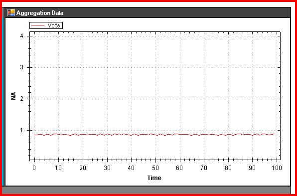
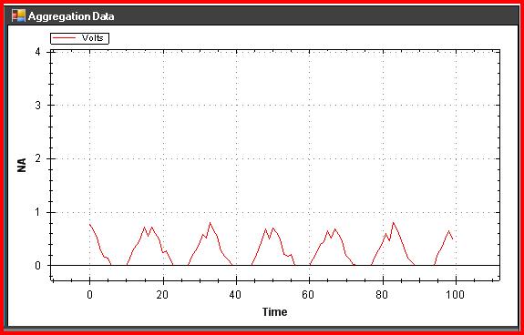
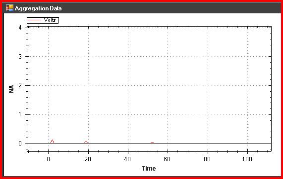
When I start the acquisition first, everything works fine (that is, I get a stable output of the card of all about 700mV). After about an hour, I begin to see spikes down to ~ 0V and it worsens gradually until the entire signal is down around 0V (see images below). Check out with my Fluke 179 voltmeter reveals that the measure is in fact ~ 700mV but DQA reported erroneous information. The Exchange hot of an analogue of different entries and I receive the same signal. If I disconnect the acquisition of data from the USB port and then restore power, (about 20 years ago), the signal is recovered and stable again for 60 min... Then the cycle repeats.
Any ideas?
Original waveform
60 min wave form:
90 min waveform:
Therefore, the interfering signal at 60 Hz. If you are in the United States, then you probably have power line interference and perhaps a ground loop.
You see drifting even if you generate a signal with a resistance voltage divider? Connect 4700 ohm of the V line + the DAQ hardware on pin 5 of HAVE it. Connect form 1000 ohms pin HAVE to HAVE Gnd. This will give you ~0.9 V. watch that for a period of time see if he slips up.
Lynn
-
Calibrate the NI 9265 cRIO module
Hi guys
I have a few output current modules NI 9265, analog and I would like to perform an external calibration using a digital multimeter to 8 1/2 available in the laboratory. I tried to do it using a MAX interface, but I discovered that it is not possbile because the analog module is installed in a cRio-9074 control. I don't have this controller and an EtherCat chassi to install modules. Is there another way to calibrate with DAQmx with the NI 9265 installed in the cRio control? Would it not possible in LabView?
Hey Lane,.
Unfortunately cRIO or EtherCat frame can be used with DAQmx since they do not belong to the data acquisition platform. Some (e.g., NI 9265) cSeries modules are supported by both platforms, but it can only be calibrated by a cDAQ platform.
If you check the manual for calibration for the NI 9265 (if you have not yet verified) you will see that it is recommended to use a cDAQ-9178, including a cDAQ chassis 8.
http://www.NI.com/PDF/manuals/372667b.PDF
If you really need an external calibration, please contact your local office of OR to get more information on calibration Services.
Best regards.
-
Registration of the analog inputs in continuous (Clipping)
Material:
(1) USB NI CDaq-9174 chassis
(2) NEITHER 9234 Analog Input Modules
(1) digital input module 9402 OR
Goal/Requirements:
To read the analog inputs continuous only in digital input is "high".
Problem:
Timestamp in log file prooves that logging is not continuous. It seems that the first seconds of 0.6 of every second is recording, I guess the other 0.4 is used to write custom? I can't use VI SignalExpress for this application because logging must be triggered by a high digital input.
File is attached. Thank you all!
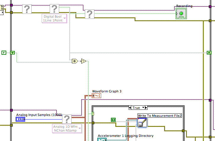
To detect changes in the digital input, you need to compare the current value to the previous. The easiest way to do this is to plug the output of digital playback on a shift register. The Boolean function involves will tell you when a transition has taken place. See the central part of the image below. If you exchange the true and the false case of case structures, you not the inversion function. Look at the help file for more information on what the function actually implies.
You must also change the wiring of the name of input for writing custom file FIle.vi so that the name is automaticlly changed. Depending on what you want the naming system to be, that it can be simple or rather complicated.
Lynn
-
Impossible to get more than 1 channel to read with DAQmx cDAQ-9172 under Windows 7
I have the cell load, voltage, and input thermocouple connected to a cDAQ-9172. My sensors entries have been scaled and verified in MAX, and all of them work. DASYLab 13, the driver is "dcDASY.dll" and the hardware configuration is "NI MAX.
When I add a task NEITHER-DAQmx Analog Input (that is, a set of scales) it appears correctly. If I add a second channel of the task and select it, I get this message:
'Channel of task name saved with the module is not available. DASYLab resets the module parameters for usable first channel name task. »
The name of the task remains the same for each new channel I have Add. If I change the name of the task by using the tab to the drop down menu, it says:
"You have configured several ways out for the module. If you modify the task, you lose the settings. You want to change the task? »
Both display the same data channels, and I can't work simultaneously several channels. It seems I missed something obvious, but I can't.The parameters are:
Measurement and Automation Explorer 4.6.1
NOR-DAQmx 9.0Material:-cDAQ-9172
Slot 1 - NOR 9215 (0-10 Vdc analog voltage)
Slot 2 - NEITHER 9211 (thermocouple)
slot 3 - NI 9481 (relay)
slot 4 - NI 9237 (entry deck w / excitement)
housing 5 - OR 9402 (DIO)
slot 6 - NI 9263 (0-10 Vdc output analog)Thank you
You can't perform different tasks (continuous) HERE on a single chassis. The first tasks that starts will be 'the resource booking '.
Combine the AIs of the various modules in a single task (see photo): start by creating the task of thermocouple. Then add AIs 9237 (e.g. Kraft) and 9215 (volts) using the button with the blue, symbol. Set the mode of synchronization of the task of "continue". Save the task, start DASYLab (second photo).
Change a task (adding channels, etc.) to the MAX while DASYLab works always, will result in unexpected behavior. To synchronize the configuration of MAX with DASYLab, you will need to close/restart DASYLab or use the 'sync' of the function (see photo 3 "syncmax.jpg"). You can set this function as a shortcut by right-clicking on one of the eight green or grey circle things.
You should think about an update of the MAX/DAqmx drivers. 9.x is a little outdated.
Updated at least DAQmx 9.9, better 14.x or 15. 0 (stay far 15 1.x).
-
9625 OR compactDAQ/compactRIO compatibility?
Hello
The question I would ask is if NEITHER 9265 (current analog output module) is compatible with
compactDAQ or not.
Comparison tables shown attached PDFs, ' NOR-card technique-ds - 219.pdf ' , says no compatibility
for compactDAQ.
And in the other pdf ' NOR-card technique-ds - 220.pdf ' says 'Yes' compatibility.
Which is correct?
Waiting for urgent response... Thank you
Hi Waqar123,
I'm sorry for the confusion. According to the documentation below, the NI 9265 is compatible with the CompactDAQ or CompactRIO.
http://www.NI.com/white-paper/8136/en
Also, on the page of the product linked below, according to the specifications that it is listed as CompactDAQ and CompactRIO Form Factor.
http://sine.NI.com/NIPs/CDs/view/p/lang/en/NID/208808
The 9265 is compatible with CompactDAQ and CompactRIO. It seems that the PDF form technique OR ds 219.doc which you logged in your post is incorrect and I will work on having fixed. Thank you for that bring to our attention.
-
Looking to design an application to talk to a peripheral part 3 on DeviceNet. I have a cRIO-9035 and LabVIEW 2015 SP1. The module NI 9882 does support loading EDS files?
Hi JY,.
Sorry to say that neither 9882 cannot load the EDS file. Single card PCI or PXI can load.
Thank you!
-
Accelerometer for several modules in a cRIO
Dear all,
I try to connect my model 805M 1 accelerometer (form is attached) to one of our cRIOs in lab, I think I need some advice because we have two cRIOs and bunch of modules I want to use them instead of buying another module. We have these controllers and modules:
NEITHER cRIO-9073
NEITHER cRIO-9024
NEITHER 9265
NEITHER 9237
NEITHER 9205
NEITHER 9203
I think I can excite (he needs 3 v to 5.5 v) the acceleremoter with for example NI 9237 and read it with NI 9205. Am wrong me or is there another combination that I can use?
I appreciate your help.
Best,
Bardiya
BAK777,
Yes, you can use the NI 9237 module to provide the voltage using a custom voltage customized by excitement and ignore the input data for this task. You can read in the output voltage of your accelerometer on the NI 9205 module.
According to the characteristics of the accelerometer signal, it might be useful to research using an Analyzer of dynamic signals (DSA) module, such as the NI 9234, which is made for the acquisition of accelerometer data applications.
-
NEITHER 9234 with quasi static analog voltage
Hello
I have a NI 9234 (4 channels + / IEPE 24-bit 5V) attached to a chassis cRIO module. This module is ideal for accelerometers and microphones where the tension is in constant evolution (ie; measures of variation rates).
I also have a module OR 9237 (4 channels 24-bit full-bridge module analog input) attached to the same cRIO. This module is ideal for measure variable voltages of strain gauges (quasi static and dynamic loads).
The attached graph shows the two channels, collected synchronously, but as you can see the (red trace) cell breaks down (as it should), but then drifts back to zero on its own, when in fact it should remain low just like the extensometer is beam. After all, the two sensors are physically secured.
Q1: Would that have something to do with AC/DC module 9234 internal coupling?
Q2: Is it really possible to collect "quasi static" ongoing tensions by using a NI 9234 module?
No explanation as to why this occurs, or if there is a way to remedy this would be appreciated.
Kind regards
Andreas
Coupling AC/DC must do a lot with your question. In mode AC voltages static will be fitered outside and the 9234 measure indeed only change voltages. In DC mode, the voltage goes directly to the AD converter and you can also detect static tensions.
A minute of Googling gave me the answer, this load cell electric piezo can measure dynamic changes, as any charge will escape the path the lowest resistance and the signal will go to zero after a certain time. I guess the other device you were using higher internal resistance (which is relatively low on the 9234), so it takes more time to what he flees, but he also took on the picture you attached your second try.
Here you can find more example under the title
"WHY ONLY DYNAMIC FORCE CAN BE MEASURED WITH SENSORS OF POWER PIEZOELECTRIC"
http://www.PCB.com/techsupport/tech_force
Andreas Jost
Technical sales engineer
National Instruments
-
NEITHER 6052e: can I re - route the analog output of DAQ for PFI?
Hello
Does anyone know if it is possible to route analog output to one of the PFI (e.g. PFI0)? I use NEITHER 6052e and I would do the following: 1) output a signal to DAQ0; 2) then a few hundred milliseconds a signal of DAQ1; and then 3) read out a simple analog pulse on any output connector external to trigger an external device.
Thank you very much for your help!
Hello sometimes.
Could you please provide more information about your hardware configuration:
What devices are DAQ0 and DAQ1?
Are you using a PXI and PCI 6052?
When you say AO reroute to PFI do you mean you're trying to wire AO into a PFI line for release purposes or are you trying to exit and the analog signal of a PFI line?
-
I tried to load Flash Player on my XP computer but have of find undesirable equipped engines, namely Binkiland and Bing, neither of which I wanted to and I can't delete them because they do not appear in the list programs. Can you please help.
Hello Maria,.
Thank you very much for the link, which worked well. Some of the other times that I tried to load Flash Player were presented by the site and also the search engine. You will understand that I am not very computer savy!
Once again thank you.
Chris.
-
NEITHER USB-6210 - the analog ground-sharing?
Dear gentlemen/ladies,
I use NI USB-6210 Council and I have four different devices that I need to join in. The problem is that I have to measure all these four analog signals in LabView with the referenced Single-End Mode, which means that I have four different pins to connect in the same slot of analog ground.
So, I would appreciate ideas on how to do it. Is it possible to create more analog grounds by software, for example? Or is there an electric simple component that I can use easily share location on the ground for several pins without causing interference to signals?
I thank very you much for your response, already in advance.
(My apologies if this forum was not one to correct for this post).
Hi Stephanie,.
You can't create more analog designs. On other devices, there are several Earth pins, but they are connected all in-house.
You simply link them all to pin GND AI because it is what it is.
I hope this helps.
Best regards
Maybe you are looking for
-
Compac Presario CQ57: operating system not found
Operating system not found
-
What part number PSA67E-001001EN see - is this a problem or serial number - just bought this laptop on e - bay and won't work - someone can help me. Supposed to be wifi but does not connect via my router broadband
-
I remember I have delete a file which is unknown to me.then when I opened my computer it does not open the way in which it will open itself. There is an error notice appear.
-
Display settings stuck on 4 bit to an absolute minimum resolution
Hello, I have an old Packard Bell iMedia PC running Windows XP Media Center edition. About a year ago I started having display problems, the monitor would go black all of a sudden and then turn it on again. This started happening more frequently unti
-
[20/07] Update Xperia U 6.0B.1.576
Hello! I tried to update my phone with the PC Companion for a while now, but when it comes to * audit stage of phone, my phone turns off by itself (and I guess that's what he should do) and the screen will continue to load for some time before tellin