NEITHER DAQ CARD FORSCANNING PV MODULES WITH 10mA lIGHT SOURCE
WHAT 10mA TYPE OR DAQ USB CARD for SCANNING PV MODULES WITH light SOURCE AND THAT SENSORS CAN BE USED?
Thank you!
Hi ellisemuhire,
If you can provide details on this type of functionality you need (inputs/outputs analog, digital input/output, etc.) and some details about the signals, you will work with I can recommend a USB DAQ product for you. We have a wide range of products, so I'll need some information to make sure that I make the best recommendation for you.
Tags: NI Products
Similar Questions
-
I use the outgoing/incoming analog DDK with the DAQ 6341 SMU map.
The examples, for example aoex5, show a single timer (method outTimerHelper::loadUI), but the example shows the DMA loaded with same size of vector data.
There is a comment in the outTimerHelper:
 call rogramUpdateCount, which implies that memory sizes different pad per channel can be used.
(the comment is: switching between the sizes of the various buffers is not used)
Nobody knows what should be the format the DMA buffer for data from multiple channels with different frequencies?
For example, we want a0 with a sinusoid at 1 kHz and a1 with a sine wave of 1.5 Khz. What looks like the DMA buffer?
With the same frequency for each channel, the data are interleaved, for example (ao0 #0, ao1 #0; ao0 ao1 #1, #1,...), but when the frequencies for each channel is different, what the stamp looks like?
Hello Kenstern,
Data are always intertwined since each card has only a single timing for each subsystem engine.
To AO, you must specify the number of samples that will be released to the AO. You also specify the number of channels. Because he didn't is that a single engine timing for AO, each AO will be channel will be updated at the same time to update clock tick. Data will be interlaced exactly as shown in the example because each channel AO needs output at each tick of the clock to update. The data itself can change depending on the frequency you want to copy.
kenstern wrote:
For example, we want a0 with a sinusoid at 1 kHz and a1 with a sine wave of 1.5 Khz. What looks like the DMA buffer?
With the same frequency for each channel, the data are interleaved, for example (ao0 #0, ao1 #0; ao0 ao1 #1, #1,...), but when the frequencies for each channel is different, what the stamp looks like?
In your example, you must come with an update rate that works for the two waveforms (sine waves of 1 and 1.5 KHz). To get a good representation of a sine wave, you need to update more than 10 x faster than your fastest frequency... I would recommend x 100 if possible.
Update frequency: 150 KHz
Channels: 2
Then create you stamps that include complete cycles of each wave you want to produce based on the frequency of update. These buffers must also be of the same size.
Buffer 1: Contains data for the sine wave of 1 KHz, 300 points 2 cycles of sine wave
Buffer 2: Contains data for the sine wave of 1.5 KHz, 300 points, 3 cycles of sine wave
You can Interleave them as before. When the data are performed through the ADC, they are out different sine waves, even if the AO channels are updated at the same speed.
-
Data acquisition in LabView for other suppliers DAQ cards that NEITHER
Hello
I am a beginner in LabView programming. I have a 32 channels base PCI card DAQ (i.e. PCI-1602 of the manufacturer, ICPDAS) and I want it to interface with Labview 8.5.
So how cards DAQ in Labview 8.5, which are manufactured by other suppliers that NEITHER? Should I DAQmx (or some other driver) for that?
What are the other drivers/components required to access of data PCI-1602 (device) of LabView 8.5 acquisition card?
(1602-PCI card driver are installed in my win XP and dispalyed in Device Manager).
Please provide some tutorial above mentioned the problem to interface.
Please guide me in this regard. Thank you
Waqar123 wrote:
Hello
I am a beginner in LabView programming. I have a 32 channels base PCI card DAQ (i.e. PCI-1602 of the manufacturer, ICPDAS) and I want it to interface with Labview 8.5.
So how cards DAQ in Labview 8.5, which are manufactured by other suppliers that NEITHER? Should I DAQmx (or some other driver) for that? You will need the drivers from the manufacturer, of the Board of Directors. In your case, "ICPDAS.
What are the other drivers/components required to access of data PCI-1602 (device) of LabView 8.5 acquisition card? Same as above.
(1602-PCI card driver are installed in my win XP and dispalyed in Device Manager). Ok. Then take you care of my 2 answers above.

Please provide some tutorial above mentioned the problem to interface. To learn more about LabVIEW, I suggest that you try to watch some of these tutorials.
Please guide me in this regard. Thank you
According to what you do with the DAQ cards, they can do the job however, from experience, there are some functions that I could achieve with the cards NOR that I couldn't with 3rd-party maufacturers. This does not mean that this is your case. However, it is worth noting that it took me a while to understand why the code has worked with a single data acquisition card (NOR) but not another (Non-OR).
The drivers that you have installed may or may not include examples and code in VI. They may be DLL. If this is the case, you can write LabVIEW "Wrappers" around these functions, as it will simplify your life. If the drivers are in the form of DLLs, and there are no examples of LabvIEW or available VI, you must read on node library function call.
R
-
selection of the daq card to get the angular position of 6 motors with encoder
can you suggest me best daq card to use 6 positions of engines as outputs using encoders attached to the engines. I'll use single window for each engine. Or what can I use a single window for all the coders of engines?
Hello Prabhakar7117,
You need a counter for each encoder. Because you are going to use 6 encoders, you should get a DAQ hardware with 6 or more counters. Take a look at the PCI-6624 or PCI-6602. Another option would be a CompactDAQ chassis with modules that are able to access counters. Take a look at them.
KB which cDAQ Modules can be used to access the counters of the shipped?
Best regards
Alina M
-
MAX with replication DAQ cards
Hello
Hope someone could shed some light on this
Its a long time since I've used Labview & MAX and am a little rusty right now.
I'm trying to upgrade an old data acquisition system to a newer version.
This is because originally one full working backup system was necessary, but because the old DAQ cards are obsolete,
a simple update was necessary.
Old system:
LabVIEW 7.1
MAX 3.1.1
Data acquisition card: PCI-6023E
New system:
LabVIEW 7.1
MAX 5.0
Data acquisition card: PCI-6220
There is no change in the Labview application.
In the new 5.0 MAX.
I'm trying migrate/replicate all virtual channels & settings of the old system.
I managed to set up a new configuration using file for the acquisition of data from the old system.
This resulted in the creation of chains of virtual of NOR-DAQ traditional under the District of data, which is what I wanted.
But the problem is, all the channels received a red cross.
Clicking on properties of the individual chain shows that no device is selected in the hardware section. There is none to choose from.
Under devices & Interfaces,.
The new card is correctly installed and running.
Appears as > NI PCI-6220 'Dev 1.
How can I make this device available in virtue Traditional NOR-DAQ virtual channels in the data area?
Is it because the new MAX/data acquisition card requires the method task NOR-DAQmx to create virtual ways?
I want to migrate channels instead of recreating that there are a fair few and each with their own settings.
In the old system.
Under devices & Interfaces,.
That's what it shows:
-Devices of NOR-DAQ traditional
PCI-6023E (1 device)-OR-DAQmx devices
-PCI-6023E: "Dev 1.The device is recognized under the District of data - Trad VC through NOR-DAQmx devices.
I can attach a screenshot for systems if it would help at all.
Thanks in advance!
-Ram of Aust
Bad news... Your most recent 6220 is a M-series it is * not * supported by NOR-traditional DAQ. This is why it does not appear as an option under the traditional OR-DAQ driver. To use the most recent data acq card, you * must * swtich above DAQmx.
Your old 6023E Board should be accompanied by one or the other pilot (but never both at the same time), so it may be be jointly installed a print while you set on the (tedious) company to recreate channels for your new Board in DAQmx.
-Kevin P
-
A module C - DAQ exists which will interface with standard RV - C?
Module C - DAQ exists that if interface with standard RV - C (vehicles recreational CAN)? RV - C seems to be a variant of J1939 according to Wikipedia.
I would use 9861 OR or NI 9862. I'm new on CAN protocol and evaluate some assistance.
I've never used RV - can, but according to Wikipedia, the rate is 250Kbaud, so you'll want high speed CAN peripheral, 9862, you can set baud rate on init of the material. After installing XNet and cDAQ software, you have a max bus monitor and several examples in the example Finder to read and write raw images. After that, you'll want to read on the standard to understand how to format and analyze the data.
Also if you have any questions, you can post on the Sub-forum Auto , they can probably answer more specific questions.
-
Synchronization of several high at different frequencies of sampling DAQ cards.
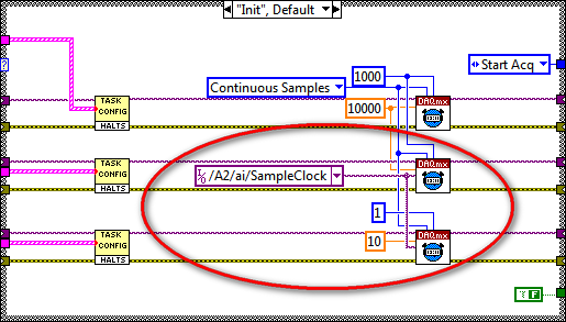
I'm having sync problems 3 high DAQ cards with different sampling frequencies. I use 2 cards PXI-6259 nec 10,000s samples and 1 PXI-6221 Board to interface for my SCXI modules in 10 samples/second. The problem that I discovered is the time related with the waveforms of the NI PXI-6221. When I run the code on a development computer using virtual devices in MAX, it works as expected. When I run the same code on real hardware, the stopwatch turns approximately 25 X faster than normal. I enclose the code and the config that I use.
Any ideas?
Hi NGNN CAD.
First of all, let me say that your code is very nice!
The problem is that you are using the fast sample for the device that is supposed to be slow clock:
Even if you specify the rate as 10 Hz, the clock itself is still at 10 kHz (by specifying the right rate allows the DAQmx driver determine the size of buffer etc and don't actually change your external sample clock speed - however, it changes the rate of the simulated device).
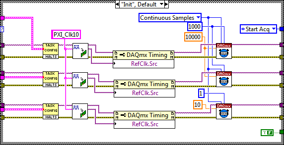
My recommendation to synchronize devices would use the built-in PLL and lock to the reference clock 10 MHz of your PXI chassis. Your devices would always share a trigger to start, but each would generate its own sample clock based on its time base that is locked to 10 MHz reference.
The code should look like this:
I hope this helps, let me know if you have any questions!
Best regards
-
Error-200284 when using two daq cards
I have an application written in Visual C++ that reads data out of a data capture with success card. However, now we want to add a second DAQ card, so we can increase the number of input channels. However, I have trouble getting the second card works fine. He continues to give the 200284 whenever I try to read the input data. I tried playing with the two loops in the same thread and with them in threads separated without result. Any ideas on what could happen?
Thank you!
Hello Kaladin,
I'll take a look at the link below to see the cause of the error, but also some common things suggested to try.
http://digital.NI.com/public.nsf/allkb/FEF778AD990D5BD886256DD700770103
Best wishes!
-
Ghost NI USB DAQ card readings
Hello
I have a question about the behavior of the NI USB-6218 data acquisition card. Right now I use Labview to take several current readings of different channels to HAVE it. I use resistors 250 ohms for each channel just as the instructions say to make the current readings. I had an incident where he has been disconnected one end of a resistance at the entrance to the port. I expected to see the reading go to zero, but instead, he began to piggback off the coast of reading one another channel give me a kind of 'reading ghost' because there was essentially no current crosses. Playback of disconnected channel displayed the current reading of the canal connected even while values went upwards or downwards. Can someone explain why the DAQ card would do that? and anyway to avoid this to happen?
Thank you.
A data acquisition uses a multiplexer to send a signal to the ADC. Due to having only 1 ADC, you will get this effect if the ability has no way to bleed. There is no way to avoid this if you disconnect the side DAQ, leaving the open input channel.
You could try adding in some amplifiers specially designed for the shunts of currents. I have used TSC103IPTwith success. This amplifier gives you a single output is completed. But I don't know what will happen with these if you disconnect one side of the resistance of the amplifier.
-
Acquisition of data using the DAQ card
Hello everyone
I need assistance with the acquisition of data of the generator of signals through DAQ cards. I plugged the signal to the SCB-68 generator where the analog inputs of the generator are connected to AI CH5 and AIGRND of the Terminal Board. Then the output of the block is connected to the DAQ card. The maximum sampling frequency of the card is of 250 kech. / s. The problem is for reason that I am not able to see the waveform on the labview. I looked at other examples to find the problem, I am, but I am not able to understand this. I want to be able to choose the sampling frequency. I attatched my code as an attatchment for you all to help me know what the problem is. Any suggestions will be appreciated.
There is no task! You have not specified any hardware (i.e. your data acquisition card) anywhere.
Here's a suggestion. MAX aperture. Find your DAQ hardware. Open a Test Panel. Implement a continuous sample of N Points to some sampling rate. Press Run and convince yourself that you get the data.
Now, while remaining in MAX, to create a task, using the same settings. Call for example something sensible ("MyFirstDAQTask" is not a good reputation).
Now, go back to your code. Eliminate the first two functions DAQmx. Wire a constant task to the DAQmx Start feature. See the little triangle down? Click it, and it should show you the tasks he 'sees', the only one should be the task that you created in MAX.
Note that 'Samples Visible' is now 'hard coded' in the task. To get its value back out, you need to put a property node Timing DAQmx after the task start and pull on the quantity of the sample, samples per channel (which, for reasons that escape me, is a Dbl, you need to convert to an I32 before importing it into the while loop).
Bob Schor
P.S. Thank you to join your code.
-
DAQ cards not selectable, that listed in MAX
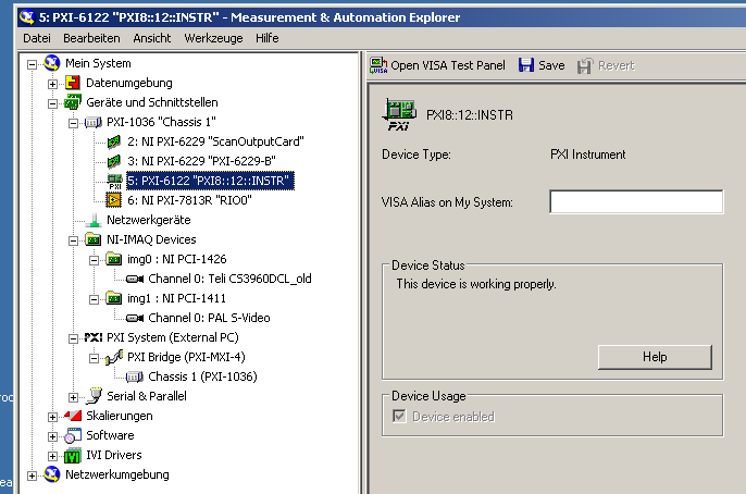
I have (re-) installing a PXI-6122 card on my computer. The device is then entered in the measurement and Automation Explorer, but differently from what I'm used to:
-It's another symbol than two PXI-6259 cards I have (see image below).
-It is not possible to create a task for the device using MAX because there is no such button.
In addition, in LabVIEW 2010 "device" or "physical channel" enumeration control, it is not listed (unlike the two PXI-6229 cards).
First of all, I knew that the card is broken. But it works correctly on another PC (with its own PXI chassis). Also, if I replace the card 6122 by another of the same type, the problem remains.
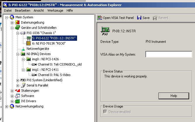
Then, I uninstalled all National Instruments software on my PC, deleted the "c:\Program NIUninstaller Instruments' file and some registry entries NOR related and reinstalled LabVIEW 2010 and device drivers. Now, the problem I had with the PXI-6122 now occurs for all three DAQ cards on the system (i.e., the two 6229 maps AND map of 6122): MAX icon is one that has the 'label PXI', tasks cannot be created in MAX and no device / or physical channels is displayed in the respective controls of LabVIEW.
Anyone have any idea how can I proceed?
-
help on select M Series DAQ card
I have type resistive sensor in response to the impact (special potentiometer). I want to first test its dynamic property (degree of sensitivity to the hose stream) and then to design a simple circuit to trigger an output transistor with threadhold predetermined impact.
I need a DAQ card to save data to a tension between the potentiometer, and my output transistor. I felt a 250 kech. / s, and 16-bit (even 12) entry is good, and no requirement for AO / DO.
I prefer to use a laptop for the data analysis. My questions:
1 should be a type USB DAQ for this application? If this isn't the case, I will return to a PCI card.
2. If the USB is selectable, I fight with the (USB - 621 x) Bus-powered and non-powered bus (such as USB - 622 x); insulated and uninsulated. Note that none of the supplied external DAQ isolated function. Among my preference: USB-6221, USB-6215 or USB-6211, which is more suitable for my data acquisition?
Thank you all.
Sue
Super! This morning, I decided to place the order with the USB-6221 and I am very happy that you assured me. Thank you, Khil.
I acctually overlooked the phrase "single channel and aggregate" x 621. I have no doubt the rate of peripheral bus before but not found where was wrong. I also discovered that 6221 provides both sinking and DI I'll use two types of supply. Now I'm comfortable with the $ 200 more on externally powered one.
Sue
-
Not selectable in LabVIEW DAQ card
I installed a PXI-6122 card. The device is listed as "Device is working properly" Max:
Now, I want to select the device to a constant of the device in LabVIEW 2010, but is not listed there:
I guess it has to do with how MAX recognizes the PXI card, see previous announcement.
Does anyone have an idea how I could make this card works and selectable in LV?
The problem has been resolved by the NI DAQmx developers:
Thank you very much!
-
Many DAQ cards synchronize hardware for PXI
I recently went through the process of getting several PCI DAQ cards in a computer and synchronize them together using a RTSI cable. I just bought two similar cards in PXI. I had to add a RTSI cable DAQmx devices manually in the measurement and automation software, and connect the cable with the PCI cards. I want to just make sure that I don't have to do the same with the PXI cards because there is no necessary RTSI cable for PXI.
Thanks for any help,
Mike
The PXI chassis has backplane triggering and clock lines so that you don't need the RTSI cable.
-
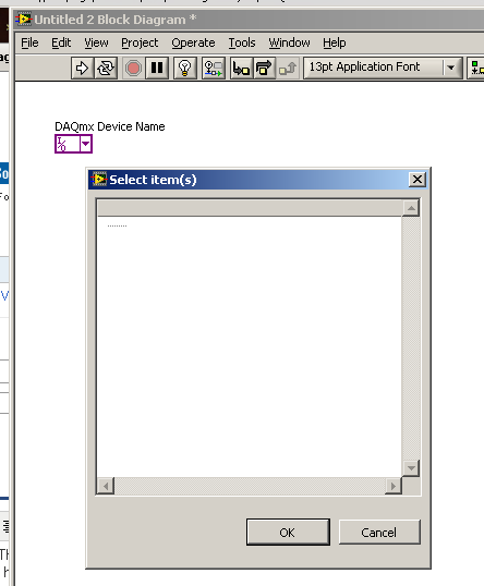
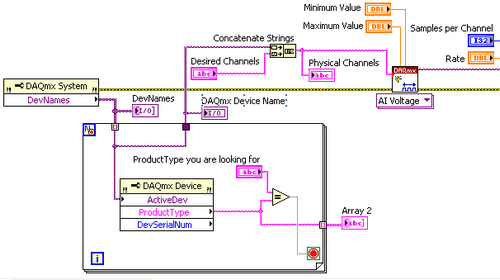
LabVIEW Application only works on a single DAQ card
Hi all:
I built an installer with DAQmx with card USB-6218. It worked very well on the target machine. But when I changed to another card USB-6218. It does not recognize the new card USB-6218. How to apply to recognize any DAQ card?
Thank you
DWT
Hi, TPL,.
Take a look at This example of the community - it allows you to find the devices via the appropriate product name, rather than his alias of device. The example could do with a few changes, but I think it will help you
Maybe you are looking for
-
HP ENVY 5646: Replacement of the ink cartridges
Hi - I have the all-in-one printer from HP ENVY 5646 and endorsed the Plan of instant ink Hp. I just run out of the "no Flash" color ink cartridge (ink cartridge black 'no snapshot' is about half full)-both "no snapshots" cartridges supplied with the
-
help - please I have the xerox Phaser printer 3010 whenever I do a draw it does not print and it shows that the printer is paused it happened he was working? I tried to cancel and restart, troubleshooting, but nothing worked it keep suspended how cha
-
* Original title: browser in xp? now that xp is outdated, which is a good or better browser to use ie or firefox ect... chrome is what Im using now but it is not supported anymore thanks in advance
-
HP Pavilion dv6 entertainment: Cortana not see internet wifi (in English and Italian)
I'm Italian, I've recently updated to windows 7 to 10. I have some questions: (1) why Cortana not see my wifi connection? Ditto Microsoft Edge.But the connection goes because I am not here. (2) why can't I activate windows 10, after update to 10 wind
-
Display will not come out of sleep mode
I have a HP Pavilion p7-1410 Office running 64-bit Windows 8. Power management is in its default configuration. When I try to wake the computer after being in standby mode, the computer comes out but the screen remains black. I know with certainty