NEITHER USB 6008 tension problem reading
Hello
I am trying to program a USB-6008 on a mac. When I connect to the input to analog 5V output I get a reading of 3.67volts, while on an osscilascope, I read a 5volts voltage. Is this normal? Need to load resistors? Also, I get the same effect with the release of tensions for the analog output.
Hi Zepp2,
Thanks for your post. The pins are you connect together on your device? Depending on the type of connection you have the wiring may not be quite right.
I found a few documents online which hopefully should help you:
Field of connection for analog signals: http://zone.ni.com/devzone/cda/tut/p/id/3344
USB-6008/6009 Getting incorrect voltage reading: http://digital.ni.com/public.nsf/allkb/95CC0CB11D7DF3D18625712E000C4ABD?OpenDocument
Input analog USB-6008/6009 reads about - 1.4V Offset: http://digital.ni.com/public.nsf/websearch/E687933C5694AB00862570BD00593CA3?OpenDocument
Please let me know if one of them will help out you.
Kind regards
Tags: NI Hardware
Similar Questions
-
NEITHER USB-6008 connect to thermocuples and pressure sensors, control valve
I am endevoring to build a gasification plant biomass for bench scale test process control plans. NEITHER USB-6008/6009 will be adapted for use as a data acquisition. I'll take RTDS, thermocouples and pressure sensors. I don't want to use industrial automation controllers. It is also possible to use the channel of analog output for sending signals to a control valve position (using sufficient current/voltage between the two drivers).
(1) OK. I just wanted to be sure that you were aware of the potential dangers.
(2) an RTD is a resistance that has small changes in resistance per degree of temperature change. To measure that you have need of a current source and a sufficient resolution in order to detect small changes. At 25 degrees C a typical RTD is 109,73 ohms and resistance ohms 0.38 per degree changes. If you had 1 my crossing this RTD voltage through it would be 109,7 mV and the voltage change of 0.38 mV by degree.
The resolution of the 6008 on the most sensitive range is 0.49 mV > 1 degree. The accuracy of the 6008 is 1.5 mV typical.
For a Type K thermocouple, voltage at 25 degrees is 1.407 mV and change by degree is 39 µV. Millivolt solving half of the 6008 translates into about 12 degrees.
If you need a source of excitement for RTD and a kind of amplification for thermocouples and RTD before she would make any sense to try to use USB-6008.
(3) I have not used anything except LabVIEW with DAQ devices and drivers. I think DAQmx can be used with MATLAB and other languages.
(4) the 6008 is the low range made by NOR. You will need to go to a more expensive camera or add signals conditioning circuits. Talk to your representative OR assistance in the choice of a suitable device.
Lynn
-
NEITHER USB 6008 voltage offset using CSR and measurement of diff.
Hi all
I am currently trying the NI USB 6008 housing and I'm getting problems when reading voltage analog using CSR or differential.
So basically, what I want to measure is a PWM signal (0 to 12V), which is divided by a divisor of tension (by two). But instead of measured 0V and 6V
I am in a position a constant 0.8V and approximately 3V.
On the side of digital data acquisition, I give you on impulses for the SSR... and it works fine.
I connect it that way: http://digital.ni.com/public.nsf/allkb/95CC0CB11D7DF3D18625712E000C4ABD?OpenDocument
Would apreciate any help
Best regards
EDIT: Attached graphics acquired are
What is the impedance of your voltage divider? The input of the USB-6008 impedance is not very high. If the impedance of the partition is large, it could cause the effect you see.
Lynn
-
Pt100 (USB-6008) configuration problems
Hello
I'm using the hardware DAQ USB-6008 (I know that's not accurate and all) and I use the Pt100 (QAP2010, click for plug technique).
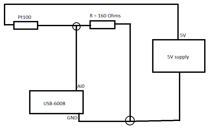
I connected it like this.
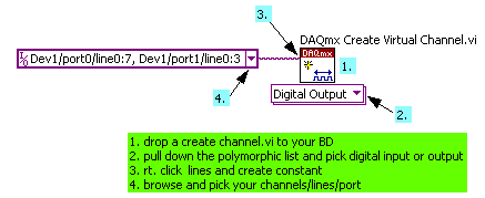
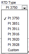
Now in LabVIEW, these are the only options (DAQmx new task-> acquire->-> RTD temperature signals).
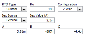
If I choose for custom settings, I get these options (I don't know what variables that is).
I use a small greenhouse where I need to measure the temperature and humidity and control environment (by using a fan to cool the cartridges to greenhouse and heat to heat).
My goal is to read the temperature using a graph on the front panel.
Can someone help me how configure/choose the right options? If you need more information I'll provide them as soon as possible!
A quick search for RTD class B shows the precision and the coefficient. As Fan Ravens stressed resistance according to the temperature is plotted in the data sheet. To control the temperature in greenhouse, a simple calculation of the slope of this graph is not good enough.
Note that the USB-6008 case limited an active player on the outputs analog and it controls only the voltage. So you will need at least one external resistor and possibly and external power to excite the RTD. These options that you have linked is not applicable to the USB-6008, which is a very simple device. You should perhaps simply to measure the voltage and calculate first resistance, then the temperature.
Lynn
-
Dear all!
I'm looking for help on the NI USB-6008 case. I'm putting in place 4 K thermocouples using this USB-6008 4-channels. I made an express VI in the Labview 8.5 and I have installed all these 4 channels in this VI. The VI is attached for your review! Come to the problem! I get strange readings of these 4 channels even if I have no thermocouple connected to the terminals with respect to this USB-6008. Please help me and explain what is happening? Why am I getting these strange temperature readings while there is no connected thermocouple?
Greetings to all!
Tajim
Dear all,
I'm sorry for not attaching the screenshot of this configuration! Here, it's this time!
Kind regards!
Tajim
-
Hello
I have a problem with some NI USB 6008 OEM.
They do not work! I have attached to my PC and the light starts flashing, Windows detects new hardware and everything's fine (the same way it usually works with the regular OEM-NIUSB6008 Board, not).
Suddunly led turns OFF, and the jury never come back to life again. I run the MeasurementStudio, and I see the boards with a red cross or without serial number (when they are shown as if they were present in the system).
I bought 10 boards and I don't want to try with anyone, because I don't know what is happening and I don't want to kill them all :-(
We have developed some equipment with regular tips and there is no problem... What is the mystery with the OEM ones?
Help, please.
Thank you!!
Hi Luciano,
Thanks for your response and documentation on the flashing led behavior. It helped me a lot to know that if the led is flashing, it could be because it is not properly initialized.
In fact, I had the 8.1 DAQmx version installed on my PC that worked perfectly well with regular advice to the NI USB-6008 (boxed version).
When I plugged the OEM boards, the system seemed to load the drivers and then a message pops up saying "your device is ready to use", but as you know when I opened MAX he didn't have a serial number, or sometimes, he appeared with a red cross.
So, I downloaded a newer driver: DAQmx 8.8. ... I installed it on my PC (first remove DAQmx8.1) and it worked

So, the problem is solved! The problem was, I think, because of the bad initialization of the device. The problem is solved by installing a DAQmx 8.8 version. It works very well with regular and USB-6008 OEM boards.
-
NEITHER USB-6008 can measure an AC voltage
Now I am doing a project, but don't know if DAQ can measure an AC voltage or not, the acquisition of data that we use is USB-6008.
Yes, it can measure AC in the range of +/-10 volts and have a sampling rate of 10kS/s.
Application engineer OR
-
NEITHER USB-6008 outputs in series to generate 10 V
We wonder if it is possible to connect the AO0 the AO1 as a series voltage source that generates 5 + 5 Volts?
The datasheet is not say, do or not, but he says they are independent.
Worst case being short, one of the outputs short-circuit if the ground is common?
-
NEITHER USB-6008 and Linux Comedi compatibility
Hello!
Could you tell if NI USB-6008 compatible with:
-Driver Linux Comedi
- NI DaqMx Base
If it is compatible, please give me the link for documentation on installing and programming.
Thanks in advance,
Vadim.
Hi Vadim,
What version of DAQmx Base you trying to install? I recommend you to install NI-VISA first, version 4.5, here. Please let me know if this does not work!
-
NEITHER USB 6008 AI acquisition and generation of pulse
Dear users of LabVIEW,
Greetings for everyone. I am a beginner of LabVIEW and I have a problem that I solved partially. I would really appreciate your help and suggestions that I searched for days without a bit of luck. The problem is as follows:
I am the acquisition of tension HAVE (continue) 4 to 8 accelerometers. In the meantime, I send you a digital output signal each time when you click on the sampling frequency (i.e. 1000, 2000, 3000,...) If the sampling rate is 1000). In other words, try to send a signal of output digital (at a frequency n Hz) at intervals of 1 second (depending on the material). To make the digital output signal begins to blink a LED every one second. In addition, I need to write signals (voltage) AI and the LED blink timestamps PC (software) separately. All stages of the above are followed in my .vi program, but the real hardware/software level operations kill my timestamps. In other words each LED flash timestamps are not accurate, when I use LabVIEW measurement file express VI (the difference is not at least to the third decimal). In addition, the timestamp is kinda OK when I disable the file LVM write VI. Onemore thing I've noticed is that physically the LED blinks every second two times, I feel it's because of the shift register and loop delay of a second. Is there a way to control the speed of blinking (i.e. Boolean State must change to every 500ms without delaying the inside while loop).
Results and comments:
LabVIEW 2011 .vi, timestamp of files with or without generator of LVM (express VI) files are all attached. Please note that there is a considerable amount of drift in the consecutive timestamps when the file LVM generator is used, on the other hand there are derivative of 0.001 ms when the file LVM generator does not. The reason for horodateurs PC have is about aligning the various measures or observations or events to global time scale.
Please give me any suggestions or help me do at least accurate to milliseconds in VI of witten. Finally, is there any USB DAQ module relatively inexpensive which allows to send an impulse to directly from channel impulse of output digital channels when the "n" sampling frequency Hz is obtained by level of material which could all be accurate, so that the software timer is completely reduced to a minimum. Although there are very material sophistiated of NOR, but our goal of this project is to build and test the system profitable.
Thank you and I really appreciate your time and effort inavluable. Have a great weekend!
Just change the samples to the constant playback at the entrance of the DAQmx Read.vi from 1000 to 500.
Lynn
-
NEITHER USB 6008 help to order 3 relays.
Hello! I have a DAQ 6008, and I need to control the three relays for the filming of lights, so I scored a VI to activate the relay through three buttons. My problem is that I don't really know what kind of relay that I need. I need something like 5VDC to 230VAC. What do you recommend?
You will need a driver-relay or transistor to provide current to fly this relay.
On a datasheet for the relay, tried google? The part number printed on the side of the relay.
The ULN2003A is a good relay driver. A 2N4400 transistor will do the job too. Both are very easy to connect.
-
How to connect my potentiometer (3 connections: wine, Vout & amp; common) to USB-6008
Hi looking for help connect my knobs to my DAQ USB-6008. Essentially got some linear and chain of pots that will be connected to the fitting of the parts to give a linear movement of DC output voltage. Got DAQ USB-6008 DC output read and display in LABview.
The pots have 3 electrical connections:
1 input voltage
2. output voltage
3 common
Entry and common connections are connected to my power supply DC leaving a single output voltage wire.
1 should I connect DAQ in premium or CSR mode?
2. as I have only a single output connection (as input and common are atttached to food) what can I connect to GND mode CSR (or the terminal for the differential mode - ve)? Can he remain unconnected?
3. do I need to connect anything to the output of data acquisition channels? or data acquisition will read my entries and display them in LABVIEW?
Excellent. Thanks for your reply. Think about it, as I have many pots to connect up to this unique DAQ so if I use the DAQ outputs to power pots, then I would be limited to two pots on the DAQ specification?
If I use the other method and hang the pot common and input for external power supply-/ + terminal and the hook to the top of the pot then you suggest also, I need to pin 1 ground output to the AI1 on data acquisition. What is all the Earth? What do you suggest as a land? If I go down this road then allow me up to 8 pots on this data acquisition? (And I guess each other the GNDs would also need to be connected to each other input used?)
-
Cannot read the digital channels as physical on USB 6008
Hello world
Sorry for maybe a stupid question, but I'm stuck and can not find the solution.
I can't read my outputs digital my USB-6008 as physical channels but only as global chains. Is this normal? What can I do to work around this problem?
Thank you, any help is very appreciated.
-
Reading NI USB 6008 of executable
Hi all
I tried to find a solution in existing topics, but unfortunately could not find a suitable solution.
I use a USB-6008 read a voltage on ai0. When I run the VI with the USB device connected to my development pc it works very well (DAQ assistant was used to read the value on ai0). After making an executable on my development pc also works. However, when I move the executable file on the computer on which I want to use it does not read voltage. If I start NI Max, I noticed that the computer is able to read the value, so physically everything should be good. To me, it seems that some link/link is missing from the software. Anyone know what may be missing/defective in my executable?
OR DAQmx is installed on the computer on which it is to run.
Is the device and channel named in the same way on desktop deployment as was the development of your PC? Display the MAX on each PC and compare.
-
USB 6008 weird analog voltage reading
Hello
I use the USB-6008 to measure a voltage of a Lithium battery, 3.66V.
the battery come with a blocking diode (in series with the battery) of 1N5820, who have a fall of voltage drop of 0, 1V.
battery with diodes in series (this is the way in which the battery is shipped with)
-measure with DDM yield 3.66V without you connect to usb6008
-measure with DDM yield connected to usb6008 (putting OUT VOLTAGE USB6008) 3.59V
-able with USB-6008 performance 3.59V connected to usb6008
battery with diode removed
-measure with DDM yield 3.66V without you connect to usb6008
-measure with DDM yield connected to usb6008 (putting OUT VOLTAGE USB6008) 3.66V
-able with USB-6008 performance 3.66V connected to usb6008
Thus, it seems that the problem is in the led in the series. This is why the battery voltage has fallen to 0.07V? the series diode will hurt the USB-6008?
Maybe people who know the circuits inside the USB-6008 can give me an answer.
Thanks in advance.
Hi learnerd,.
The fall that you see is falling forward in the diode. As an entry class device, the USB-6008 case has a relatively low input impedance (144kOhm) and thus draws a little current of the device. Looking at the datasheet of the 1N5820 (http://www.onsemi.com/pub_link/Collateral/1N5820-D.PDF), Figure 7 shows that at 25 ° C, a draw of 50mA will cause a fall front of 200mV. While the figure does not extend the curve below 50mA, extrapolating the given curve would indicate that a drop of 70mV would cause only a few current microamperes.
A DMM will have a much greater input impedance (GOhms instead of kohm) and won't draw enough current to influence the measure, that's why you wouldn't see the decline with only the DMM.
The diode will not harm the USB-6008 somehow.
Good luck with your application,
The f
Maybe you are looking for
-
All my Firefox settings and data will be lost if I change my ISP? Thank you.
I'll change ISP from Orange to the BT shortly. I wonder if I'll have to re - install Firefox and re-enter all currently registered, such as passwords and so on.
-
Why can't I burn pictures to a Flash Drive in Vista?
Right now, I have Vista 32, but waiting for delivery of a new laptop Dell Inspiron 5720 with Windows 7 in a few days. I want to burn my photos on a Flash drive, so I can save it in my new computer, but when I click on in the Photo Gallery it can bur
-
photo attachments are not showing / download in my e-mails.
Several emails I received, I'm not able to view attachments photos
-
Vista error code install 0x8007000d
the re - install vista 32 CD after screen product key is not E:\SOURCES\INSTALL. WIM, cd is FULL program, E: is cd drive.vista Home premium. My system is self build, 4 hdd, s 2 are Raid 0 vista ultimate 64.2 were vista 32 hp, first built dec 2007, re
-
Broadcom ush driver missing for dell E6400
Help, please