NEITHER USB-6501
Hello
Could someone give me some information about whether it is possible to use the
NEITHER USB-6501
As a generator PWM to control the dimming of 18 power LED function?
calendar is not so relevant and if the pulse width can be controlled in the PC itself application the purpose would be financed
Hello ONavarro,
It is technically possible, but please note that USB-6501 as only software clocked e/s digital (e/s static). In other words the duty cycle of the PWM periodocity Ant you want to generate will be determined by a loop software, so depending on your system and the USB bus. I think that you will not be able to get a better rate of loop (ability to change the State of a digital line) less than some milliseconds (depending on the system).
By example, if the loop runs at 5ms, and I want 10 steps in my PWM, this means the period will be 50ms, therefore a 20 Hz base frequency. If you can't reach 1ms, you will get 100 Hz. If you want more than 10 duty cycle value, you reduce the frequency.
And it is NOT stable (loop software 5ms, first delta 5.8ms, then 4.9ms, 5.1ms, 6.7ms, and so on), because it is based on the software. If you need something stable and faster, choose a device with hardware synchronizing.
Best regards
Tags: NI Hardware
Similar Questions
-
NEITHER USB-6501-24-line digital i/o (OR-DAQ) with LabWindows/CVI 7.0?
Hello
Can I use a recent NI USB-6501-24-line e/s digital (OR-DAQ) with LabWindows/CVI 7.0, although Labwindows/CVI 8.x is required?
Thank you
Dayne
Hello.
In DAQmx Readme, you can see which version of the CVI are supported by the version of current DAQmx. For a map of 6501, 8.7.2 or DAQmx 8.9.5 versions work.
Concerning
-
NEITHER USB-6501 (24 channels, 8.5 my)
Hello
I would like to know that I can use the NI USB-6501 (24 channels, 8.5 my) to do my practice? Please take look at my sheet of practice before you answer. I hope you all can help me.
The MyDAQ is designed to be a material cheap DAQ generalist that students can become familiar with. NOR able to discounts for students and universities. I think that it runs for $250 for students but has lots of features and built in applications of DMM, O-Scope, generator frequency, power and a few others. They also did the connector a bit of a standard and plugin modules such as bread boards, you can buy.
-
NEITHER USB-6501 not recognized by the system
Hi all
I wrote this simple application that writes and reads a SPI frame.
My PC have Labview 8.5.1 and DAQmx 8.7.1 (the CD was provided with my unit NI USB-6501). Everything works fine.
But now I need to distribute the application, and I need to run it from a computer that does not have LabVIEW.
I installed the latest versions of the runtime of LV (8.6), and the 8.7.1, DAQmx software but the program crashes produce an error (code 200477).
I tried to install a more recent DAQmx software (8.9 full, engine of execution of 8,9 only), but the situation has not changed.
Also: I tried on two different PCs, and I launched MAX: one of them doesn't even recognize that a DAQ hardware is installed (even if Windows recognizes as a work device).
Anyway, the two PCs return error 200477.
Any help will be much appreciated.
Best regards
Is - this dev4 on the pc without LabVIEW? You can easily see the device name in MAX.
-
USB-6008, USB-6501 and Embarcadero C++
Hello NEITHER and NOR users,.
I spent a considerable amount of money several years ago on a number of devices USB-6008 and USB-6501 for a class that I teach on interfacing the simulations with realworld sensors and actuators. Write us code using Embarcadero C ++ Builder and we wrote the code to interface with the jury of EZIO AD / DA via RS - 232. The EZIO is much too slow and limited. Given advertising NOR, we bought these boards, but after several attempts to get some information OR on the way to talk to these devices directly via C++, we have yet no valid response. No, I don't want to LabView or any additional expenses. I just want to talk to them directly.
OR: are you ready to help with this, or not? If this is not the case, although wanting to refund these purchases. Announce as being accessible from C++, but you are not willing to provide any help of substance to this day...
Yes, I am self-taught, write code, and old-school enough to feel that I have a right to know how to talk to all the devices I buy. I confess my ignorance, but I'm sick and tired of secret corporate and misleading advertising.
Can someone please provide me with enough example of code to start. That's what we wrote for the EZIO:
http://www.Duke.edu/Web/ISIS/Gessler/Borland/RealWorld-Ezio.htm
We would like to start writing similar code for these materials of NEITHER. If possible, we can buy more. If this is not the case, these cards are useless.
Kind regards
Nick
Nicholas Gessler, PhD.
Nick,
When you have installed the DAQmx drivers to communicate with the 6008 and 6501, I assume you also installed programming examples? It is here that they are on my XP machine: C:\Documents and Settings\All Users\Documents\National Instruments\NI-DAQ\Examples\DAQmx ANSI C. I don't think that Embarcadero C++ Builder is one of the languages supported, so you'll need to twist your compiler, but it should give you a good start.
Tom
-
Why USB-6501 does not install on Win7?
We are in a process of migration of the old XP machine test system to the new system of Win7. All but got properly installed USB-6501. After you install LabView / DAQmx and connection USB-6501 windows could not find the drivers for this device (poster the exclamation sign on the icon of the device in devices and printers). MAX 4.7.4 detects either of the device. I looked for similar scenarios on the Forum OR and abroad and tried the solutions proposed. Nothing worked for me. I know the issue isn't with the USB-6501 material because it is functional on the old system. 4.7.4 MAXLE Win7 system detects a very well (GPIB-USB-HS) different USB device, but not for USB-6501.
I hope someone can help us identify the problem that we have struggled with for some time. Here are the differences between shipments of software on two systems:
Old system:
OS - XP SP3
LabView - 7.0
DAQmx - 8.0
VISA - 4.4.1
MAX - 4.5 (detects the GPIB-USB-HS and USB-6501.) Status on 6501 LIGHT flashes continuously)
New system:
OS - Win 7 Enterprise
LabView - 7.0
DAQmx - 9.2.2
VISA - 5.0.3
MAX - 4.7.4 (detects only GPIB-USB-HS. Status on 6501 LIGHT flashes 3 times and then road)
Germano,
The device has been appear in Manager devices, but with the yellow exclamation mark for no drivers found/expenses. Update drivers on the property page does not help.
So yesterday I spent most of the day removing all facilities OR according to the instructions, I found in this forum. Then I reinstalled the software OR in the order following, restarting after each installed:
(1) LabView 7.0
(2) DAQ 8.0.1
(3) NEITHER-488. 2 (v2.30)
(4) connected USB-6501 first. The installation of the device has gone well and is now detected to the MAX!

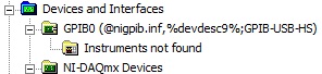
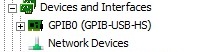
(5) connected GPIB-USB-HS. Scanned for changes on the hardware, peripheral GPIB presents itself to the MAX, but with a weird name announcement its INF file on his behalf. See the screenshots below:
GPIB device incorrectly installed:
GPIB device properly installed:
The strange thing is that this GPIB device was fully functional on my previous installation (see attachment max_report_3-23 - 11.pdf), now reinstall after its unusable (see attached max_report_3-24 - 11.pdf). Looking for GPIB instruments to help Max returns no result, but if I reconnect GPIB-USB-HS to the old system of PC all instruments are detected (for instrument scan error message see attached MAX after reinstall.jpg).
That my new problem is not related to USB-6501, maybe I should open a new forum thread.
-
Can I use a USB-6501 instead of a PCI-6503 map?
I currently use a card PCI - 6503 DIO into a Windows XP system. We have an old (7.1) version of LabVIEW. We are looking for a Virtual Machine in Windows 7, but he will not be able to communicate with the PCI Bus. We currently use a PCI-6503. A USB 6501 will work to place it?
We are looking for some intot wiring problems, but I think it will do the job.
Thank you.
-
USB-6501 - impossible to find a basic example of Labview
Hello
I recently bought a USB-6501 card and I used it in my own succesfully end and C++ programs using the DAQmx drivers.
Then I tried to move to Labview 2009 (I never used Labview) so I looked for a simple example.
I tried to boot from the example 'interactive Control Panel' (http://digital.ni.com/public.nsf/allkb/AF0F31EE5D2AD23F862573140009D7C2?OpenDocument).
I had to install the 'DAQmx Base' for him to start, as described in the previous link. now it begins (before Labview attempted to get a few missing .vi) but I get a message "error 200220 occurred at an unidentified locatio.
Then I realized this example is 'old' (as explained here: http://forums.ni.com/ni/board/message?board.id=170&thread.id=209247), and it is suggested to look for a new one in example Finder ' entry-level equipment / output-> DAQmx-> Digital measurement (or generation)-> read Dig Port.VI.
I tried, but along the way ' entry-level equipment / output-> DAQmx-> "only a folder named"Analog Measurement\Voltage"exists.
Also in the search for 'Reading dig Port.VI' does not work.
I've already spent many hours in this research and tent and the fact that I am not able to find not even a basic example, it is quite frustrating and it is making me give up the idea of using Labview.
Please can anyone give me any suggestions where find/download an example simple and minimum to use my USB6501 in Labview 2009?
Thank you
Scipione.
First, install DAQmx Base was a mistake. Uninstall it and then install the Driver-OR-DAQmx. The driver must be installed after the installation of LabVIEW. After installation, make sure that the device is listed in MAX under "DAQmx devices. If it is not, your installation is still not correct.
To search for example LabVIEW, see help > find examples. Under Input and Output hardware > DAQmx, you will find the digital generation and numerical measures. You have to look at the simple, timed software examples such as read write dig Chan, writing Port to dig, dig chan, reading Dig Port. You also have the option to use the DAQ Assistant.
-
OEM version or usb-6501 contains the IDC connector, I want to know what is the ground of the pins in the connector in order to build a daughterboard for him?
I'm guessing it uses the standard height of 2.54 mm (0.100 ") of IDC.
-AK2DM
-
I am using the IDW library to create a master by using the USB-6501. My problem is that the DAQmx write gives an error when it tries to use the 'Z' setting for high impedance. Are there workarounds for this?
6501 does not support high impedance state... inexpensive compared to high-performance and you have a low cost DIO.
Might be able to set the output to an entry, but there is still the internal pullup with that you will fight.
-
Hi all
I have a brand new NI USB-6501, and I'm looking for more help with the operation. I'm running OS X 10.11.1, LabVIEW 2013 SP 1, NI-VISA 15.0 and NOR-DAQmx Base 15.0.0. I set up and plugged my module and get the flashing green light stable. I ran NI MAX, found the module and renamed 'Motor_Module '. Then, I went to my DAQmx Base of examples and found the Control.llb Interactive USB-6501 and ran the interactive VI control that is contained in this library.
The first thing I tried was simply running the VI. I got error-200220, device ID is not valid. I changed the name of the device to "Motor_Module" and run the VI. This time, I got error-200558, a task cannot contain multiple independent devices. Create a task for each independent device.
And here I am. My ultimate goal is to have this output module signal collector type open to + 5 V. Any help would be greatly appreciated. Thank you.
Hi Sullivnc,
I would recommend you look at a few examples in the Finder for example of OR. Under input and output hardware, there is a folder for DAQmx who has a record for a digital output which has some useful examples. If you do continuous or left over, you can add more stuff to your code as a clear task DAQmx, vi DAQmx Timing, and/or vi DAQmx task is made.
-
NI USB-6501 digital output problem
Hello
I use DASYLab v.11 and I'm working on an interface with the NI USB-6501 where I'm putting a digital high on four ports.
With the module "NOR-DAQmx - digital input", I managed to read the digital inputs of the ' NI USB-6501 ".»
It's only the "NOR-DAQmx - digital output" I can't go to work.
Using 'NI MAX' of NOR I have easily can emmit my four LEDs in the way of my High/Low ports.
But not with DASYLab. When you use DASYLab tension on the ports remains unchanged.
Now, I have a switch module, generating 5/0, directly connected to the digital output module, which is assigned to my four output ports for my task.
I also tried with a module of relay between the two without success. I also tried to use 1.5 above instead of 5 without success.
I use the option 'Bus (0/5 supply) for the module "Digital output".
"NI Max", I configured the ports as "active drive.
Any suggestion of what I might be missing?
Thank you
Martin
Hmm, four ports, or four lines?
A port consists of eight lines. Each line can control an LED (ON / OFF ~ 0/5V).
If you have created a task to dig-out to control a port, 5V to this port sending sets all lines of this port to 'high '.
You need to 255 for each line one too high port (at the bit level: 128 + 64 + 32 + 16 + 8 + 4 + 2 + 1).<- eight="">
Or, you can create a dig out tasks to control four lines of a specific port.
Four lanes of the EEG DAQmx DigOut module.
Each of the channels of the modul will feed a single line of the task/device.
Four switches will then turn the lights, or turn off.
Make sure, that the 'bitposition' is the number of correct line (see picture).
-
Hi all!
I have a PC under WHAT XP 2002 (SP3) with two USB-6501 Renault connected on it. I can see two devices in the DEVICE MANAGER under the heading "Data Acquisition hardware" and the two seem to have installed proper drivers. They show their driver versions of file as 2.3.1f0. I also have NI MAX v4.6.2 installed on the computer. But Max, I am unable to display all the devices. When I try and expand the section "Devices and Interfaces", the MAX software enters a State of non-response and when he answers Finally, I get the following message redirect me to the Web site of EITHER:
There was a problem connecting to the database.
Restart your computer. Refer to knowledge base article 42HG08DD for more information
and if the problem persists, contact National Instruments. Go to ni.com now?
I could see the two Renault to the MAX on another computer with installed Windows7 and MAX version 14.
Just make sure you install complete DAQmx with the support of the MAX configuration. It is possible to enter in some States strange if you have MAX and DAQmx Runtime, but not the support of DAQmx for MAX. In addition, MAX 4.6.2 is a real version, but very old.
Note Setup below should work and will include a version of MAX.
-
USB-6501 and opto-coupler SFH615A
Hello
I'm driving an opto-coupler (Siemens SFH615A - spec link attached) using the USB-6501. I am really a beginner and I am looking
help on how I can connect it. I have tried a few options already but no luck.
http://docs-Europe.Electrocomponents.com/WebDocs/009C/0900766b8009c194.PDF
I use a Servo-Drive in a project, a motor drive. Unfortuantely USB-6501 turns out logically lines high on the servo-controller startup is
receipt of a signal. I hope I can pass the INHIBITION of the servo drive line, through the opto-Coupler, so when you start 6501 will cause the optocoupler
circuit close to inauguration of the line inhibit preventing displacement engine. The labview program will make the logic of the bass line to allow the engine to move.
Looking at the manual of the USB-6501 and previous questions, there are 2 ways to do this, but working on resistance, values etc. required is
still a bit beyond me, and unfortunately I'm a bit stuck for the moment.
Any help would be greatly appreciated, thank you.
OK got it works, I hope it will be useful for others.
My problem, I think, have no idea really, is the impedance of the I/O device. Despite everything, I used a buffer of gain of the unit with the help of the
Intersil ICL7611 powered by the + 5V line with the line of digital output connected the + IN the axis of the ICL7611. On the output, I have a
Resistance 120 ohm before the opto SFH615A. Opto is open beginning 6501 and high but closed low logic logic. Happy days until the
the next problem happens
-
Best way to generate the software clock for USB-6501 of Measurement Studio for c# VS2008
Hi all
I wonder if there is a better way to generate a clock software for USB-6501 of Measurement Studio for VS2008 in C Sharp?
I have developed a clock using C Sharp "Thread.Sleep (msecPauseTime)"; and statements to switch digital output high and low. There are a few things I noticed in creating a software clock in this way:
- The smallest delay by the Thread.Sleep command time is 1 millisecond (which means higher clock period is 2 msec-500 Hz, not holding not ball account no. 2 below).
- Sometimes the delay I see on an oscilloscope is considerably longer than the delay that I specified in the sleep command.
In my application, I create signals (a clock, a latch enable and data series) to control what an attenuator step through the USB-6501 RF connected to a USB 2.0 on my computer. This particular step RF attenuator can accept clocks with frequencies up to 10 MHz, so I would like to generate a software clock (without having to connect to an external clock to a line of input on the USB-6501) which is closest to this maximum frequency, and I think that the USB2.0 line could handle clock speeds over 500 Hz. Also, I would like to know why the delays that I see on the scope are sometimes longer than the time specified by the Thread.Sleep command. Is it caused by the suspension of the execution of my program processor for something else, as I suspect? Of course, this isn't a big deal, because it does not affect the time as my serial data and pieces change compared to my clock. However, I would like to know why it does this.
I appreciate your help.
Thank you
Jonathan Becker
Doctoral research engineer
Carnegie Mellon Silicon Valley
Jonathan,
Since the USB-6501 DIO is software programmed, you are at the mercy of the planning of the operating system and won't be able to work reliably with an external clock in the software.
You can try to set the priority of your thread 'generation of clock' to improve performance, however, because Windows is not a deterministic operating system, there are still no guarantees. Operating systems are not required to honor the priority of threads. You can find examples and information on the definition of the priorities of the threads in c# here:
http://msdn.Microsoft.com/en-us/library/system.Threading.thread.priority.aspx
Kind regards
Maybe you are looking for
-
Satellite L750/755 - DVD player emits a sound without any DVD inside
Hello, I have a questionIt's normal DVD player emits a sound without any DVD inside? I'm the ear every time the sound
-
Compute the derivative of custom
Hello world I would like to calculate a custom derivative (derived from two points to be precise) of my data. The derivative of two points means that df (x) /dx = [f(x+h) f (x - h)] / 2 h, rather than df (x) /dx = [f (x) f (x - h)] / h. I am a beginn
-
LaserJet M1122: Printer is not recognized by NAS LenovoEZ
Hi guys, I have buy a new brand Laserjet and I plugged it in the center of storage of LenovoEZ USB to share the printer on the network. Instead to recognise the Lenovo shows a 'shared device' as if the printer was a USB key with some drivers. The pri
-
had to reinstall windows and lost all files, photos and music
had to reinstall windows and lost all files, photos and music! How can I get that back.
-
Solution for blackBerry Smartphones on issues with Facebook for BlackBerry v.4.1.0.19
Hello! I stumbled upon several threads on the questions users affected by the right after they upgraded they are Facebook for new construction (v.4.1.0.19).Issues such as the screen frozen, impossible to scroll and java error message lang at the open