NI 5122 range Variable sampling rate
Hello
I use a digitizer card high-speed NI 5122 to acquire data and synchronize the sampling frequency of the frequency of the data card. For example, my first set of data will have a frequency of 13.6 MHz so I would taste 13.6 MHz. When I connect a signal 13.6 MHz to the CLK IN on the front panel of the card and write Labview code to taste at this rate (for the sample clock or reference clock), I get error message. Anyone know if its possible to have a sampling rate variable really for this card?
Thank you
Steve
Hi Steve,.
I understand that you are using a digitizer high-speed 5122 and try to use an external sample clock. What kind of error messages received when you doing? In addition, how you set up the device to use this external clock?
"" "" I would also like to point out that there is a very useful example program in the example Finder LabVIEW ('Help' to find examples) found in e/s material "Modular Instruments ' OR-SCOPE" features ""niScope Clocking.vi external EX' that allows the user to make a simple acquisition using an external clock source. To specify the source of external clock, rate and divisor, a knot of niScope property is used. You should be able to try this example and use the same method in your program. Hope this helps,
Tags: NI Software
Similar Questions
-
Hi all
I use a module 9237 for certain measures of the load. My experiences last over time and so I'm generating a lot of data due to the minimum sampling frequency. I can't define an external time base so I can lower my sampling rate to something easier to manage? Even just a sample rate of 500 s/s would make a huge difference.
Thank you
Hi cannisbellum,
9237 specifications frequency range of minimum data (fs) using the internal master time base is 1,613 kech. / s and external use master timebase is 391 s/s. The simplest would be to sample at 2kS/s and decimate your data by 4. This can be done by using 'Decimate 1 table D' or ".vi Decimate (continuous).
Rates valid for the NI 9233 OR 9234 sampling and NI 9237 - http://digital.ni.com/public.nsf/allkb/593CC07F76B1405A862570DE005F6836?OpenDocument
Best,
CARISA
-
DMM (NI 4070), how to correctly set AC Freq (bandwidth) by the sampling rate
using a NI4070 multimeter and I see the max connection is 300 kHz by respect it. But I don't understand how to set the min and max, acFrequency according to the sampling frequency or speed reading.
6 1/2 digits resolution, the speed can vary from 0.25 s/s to 100 s/s and this range corresponds to a lower end on the connection (minimum acFreq) from 1 Hz to 400 Hz.
(Q1a) - is the playback speed, controlled by the minimum setting of IviDmm_ConfigureACBandwidth? or vice versa?
Otherwise, I do not see how to control the rate of reading or the sampling frequency. IviDmm_ConfigureMeasurement only allows you to control the range and resolution.
(Q1b) - is there a way to directly control the sample rate (digitizer) or playback speed (dmm)?
(T2) - the upper limit of the bandwidth of AC always seems to be at 300 kHz... is there still a reason to reduce this maximum value?
(T3) - Finally, unlike the traditional niDmm function, the resolution via the IVI configuration should be passed as absolute value; does directly when number of digits and the beach? For example if I want to 6 1/2 digit to 300V range, I guess that by the specifications that the resolution should be set at 0.001 V... followign, if I want 5 1/2 digits to 1V range, the resolution should be set to 0.00001 V?
Hi Rjohnson,
I'll try to answer your questions as best as I can:
Q1A. The ConfigurACBandwidth function is used by the driver OR DMM to calculate the good aperautre for the measure. So yes, by adjusting your minimum frequency, you will affect your reading speed.
Q1B. Your reading rate will depend largely on your measuring cycle. To get a fast measuring cycle, there are a few things that you can adjust. You can programmatically control your time aperature, as well as your time to settle.
Q2. I can't find a reason to change. This parameter is only used for error-checking and verifies that the value of
This setting is less than the maximum frequency of the device.Q2B. I think what you say is right, but I'll need to check on that - I'll let know you as soon as.
Hope that helps. "" "I would recommend checking the explanation of the Cycle of the DMM measurement in DMM help' devices ' NI 4070" DMM Measuments "DMM measurement Cycle.
Take care!!
-
. VI filtering IIR and response: response of Butterworth filter size depends on sampling rate - why?
Hi people,
I'm not an expert in the design of the filter, only a person in applying them, so please can someone help me with an explanation?
I need to filter signals very infrequent using a buttherwoth filter 2. or 3. order of the bandpass 0.1 to 10 Hz.
Very relevant amplitudes are BELOW 1 Hz, often less than 0.5 Hz, but there is as well the amplitudes beyond 5 Hz to observe.
It's fixed and prescribed for the application.
However, the sampling rate of the measuring system is not prescribed. It may be between say between 30 and 2000 Hz. Depends on the question of whether the same set of data is used for analysis of the higher up to 1000 Hz frequencies on the same measure or this is not done by the user and he chooses a lower sampling rate to reduce the size of files, especially when measuring for longer periods of several weeks.
To compare the response amplitude of 2nd and 3rd order filter, I used the example of IIR filtering .vi and response:
I was very surprised when I found that the response of greatness is considerably influenced by the SAMPLING RATE I say the signal generator in this example vi.
Can you please tell me why - and especially why the filter of order 3 will be worse for the parts of low frequency below 1 Hz signal. Told me of people experienced with filters that the 3rd oder will less distort the amplitudes which does nothing for my the frequencies below 1 Hz.
In the attached png you see 4 screenshots for 2 or 3 command and sampling rate of 300 or 1000 Hz to show you the answers of variable magnitude without opening labview.
THANK YOU very much for your ANSWERS!
Chris
Hello Cameron and thanks for my lenses of compensation.
I can now proudly present the solution of my problem.
It seems to be purely a problem of the visualistion information filters through the cluster of the scale.
After looking in the front panel of the IIR, I suddenly noticed that the "df" of the pole size is changing with the Fs of the input signal.
For a Fs to 30 Hz, the "df" is 0.03 Hz so you see the curve of the filter with more points, see png.
For a Fs 300 Hz "df" is 0.3 Hz, so the curve is larger with only 3 points between 0 and 1 Hz.
For a 1 kHz Fs the df is 0,976 Hz, so there is no point in the graph between 0 and 1 Hz.
It's strange that for constant Fs, df of this cluster NOT reduced with the increase in the number of samples, as it does in an FFT.
However, I hope now the filter used now for the curves obtained with the proposed Lynn way and the response of greatness from the filter information fit together.
Thank you for your support.
Merry Christmas and a happy new year to all.
Chris
-
High sampling rate for 18 strings in a single task - DAQmx
Hello
My current experiences require the acquisition of 18 channels (6 HAVE custom voltage with excitement, voltage AI 12) data at a sampling frequency of 50 kHz. My question is if it is faesible using a single cDAQ-9172 chassis. Used modules are 2 x NI 9237 and 4 x NI 9215.
The previous researcher on this project used 2 different Renault to do this, but I was hoping that I could reduce it to a single DAQ to simplify the synchronization of all channels.
I wrote a *.vi (attached) to do this and write to a TDMS file using a structure of producer-consumer; However, when I run the * .vi, I can run for minutes, but the number of samples recorded for the PDM is rarely more than 100 k. Subsequently a buffer size error (attempted to read from the samples that have been overwritten) with less than 200 k samples ever record. I checked the max sampling rate (using a property timing node) with the configured task as in the * .vi and it shows a maximum of 235kHz.
I can't say if I make just the structure of the producer consumer incorrectly or if I ask too much of the cDAQ-9172 unique?
Any help would be much appreciated.
See you soon
Bart
Hi bart.s,
TiTou speaks sampling aggregate not simultaneous, so sampling rate 50kS/s is the same for all channels.
I see the problem in the loop of the producer. If your sampling frequency is 50kS/s/ch and you read that a single sample/ch you will lose data because the producer loop cannot run so fast. You should read more than one sample. I recommend you also to move your tracing to the consumption loop code and work with larger amounts of data.
The second problem may be with the error handling in your loop of consumer. Merge the mistakes of loop of consumer and producer and also add a few general for two loops off if the error occurs (for example, using local variable).
Best regards
CaravagGIO
-
Different sampling rate with the same connector AIO, Labview FPGA
Hello
I use LV 2009 with the new Toolbox FPGA and an NI PXI 7854R. I acquire an analog signal with a sampling frequency of 600kS / s. I need as the sampling rate for the processing of the data, but I also need the signal sampled with a much smaller, variable sampling frequency to a FFT.
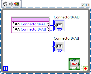
I've attached a picture to clarify, in a simple example, I'm looking for.
I tried with the structure case only take each ' iht iteration, but did not get the expected results.
Does anyone have another idea how to solve my problem? Of the, "Resampling" express VI in the funtion FPGA palette does not help me.
Thanks in advance,
Concerning
Hello
the connector for the analog input is a "shared resource", so you should he alone in your FPGA Code.
Find attached an example that shows how to perform this task of analysis.
Concerning
Ulrich
AE OR-CER
-
So maybe this is a stupid question, but I need to know because I train for a specific sound. Is there a way [to logic] to shoot/change of a certain frequency sampling rates. I can imitate the sound I'm looking for with a low pass filter, reverb and a distortion. But I don't want to 'emulate', this sound, I want to create. Then I can put my own effects and play with it like I want to. If I have to use a bunch of effects to make it sound like I want that also the addition of said effects remove the sound and sound horrible. as to where pulling the sampling frequency of the high frequency and no downs will make me THE noise that I need and always allow to add nice effects to make MY sound instead of someone else. I hope you know what I mean. Let me to you specific real once more. I want to pull or carry a certain frequency sampling rates for a sound under water. I don't want to use filters to make the sound. So can you please help me. I invited everyone locally on how to do it and nothing works. Also if this is not possible in the logic of tell me if there are third party plug ins or maybe even a different DAW that could do like komplete Kontrol or audacity.
See if this thread is helpful at all...
-
I'm new to myRIO and use it to measure sine wave (0V to 5V) of up to 10 Hz 20 KHz. I also quickly transformed of Fourier (FFT) of the signal measured in real time.
Sideways FPGA of things, I try to keep things pretty simple, just read 2 channels of AI (connector B: AI0 and AI1), therefore potentially able to read each HAVE 250 kech. / s (as the unit has a capacity of 500kS/s). Does that mean this program gets a two analog inputs data exactly every 4 microsecond? If this is not the case, how can I make sure that the data is acquired through a fixed sampling rate?
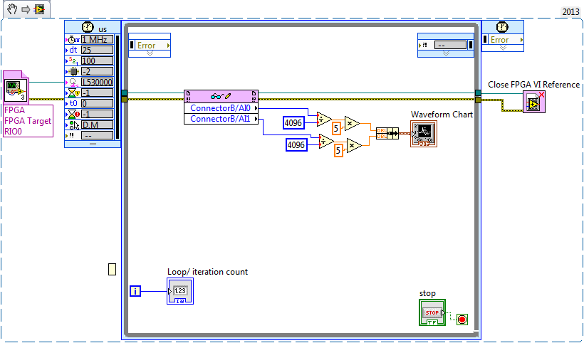
I realized that we can add to the FFT in FPGA function, but I wanted to manipulte the acquired data of analog inputs before it is sent to the FFT, which I don't know how to do now. Can someone explain me how do the arithmetic data (muliplication, division and so) on the acquired data and analog inputs to reducde the 12-bit resolution 10-bit to program FPGAS.
Later, I created a myRIO program to read analog data 2 FPGA program which continues to turn in timed loop. In the program myRIO, the timed loop is configured to 1 MHz clock source type by a delay of 25 microseconds.
This configuration means that the loop runs exactly every 25 microsecond?
When I set up the less than 10 micro second time, myRIO has stopped working. Why is it so?
Is it because myRIO cannot run as fast as FPGA?
It is advisable to make the FFT of myRIO side analog data or FPGA?
When I tried to do FFT using the power spectrum of myRIO side, he asked for waveform data. What I acquire is data analog. How can I convert in waveform data?
If I read in the forum for help, I couldn't have the full answer to my doubts
Discussions at the Forum I did reference:
A lot of good questions here, I will try to answer as much as I can so as to offer a bit of advice.
First of all, if you are looking to acquire data at a very specific rate on the FPGA, you'll want to use the Timer VI. You are also going to use a FIFO of DMA to transfer data of FPGA in real time. A node read-write using as you do now means you'll run out of samples, or read the sample even several times. The link below is a very good tutorial on how to do what I described above.
http://www.NI.com/Tutorial/4534/en/
Later, I created a myRIO program to read analog data 2 FPGA program which continues to turn in timed loop. In the program myRIO, the timed loop is configured to 1 MHz clock source type by a delay of 25 microseconds.
This configuration means that the loop runs exactly every 25 microsecond?
When I set up the less than 10 micro second time, myRIO has stopped working. Why is it so?
Is it because myRIO cannot run as fast as FPGA?
In general, you should not run a timed loop much faster than 1 kHz. Using timed inside loop knots, you can monitor the real rate of loop during execution to see if f you meet your needs of the moment.
The portion of your myRIO RT is slower than an FPGA in the sense where it cannot manage the rates of lines 40 MHz (he makes up for it by being able to work with much better pictures) and it is important to remember that it is just a computer. The advantage of a real-time operating system, is that you have more control on the Scheduler, not that he is faster (less jitter, not faster code). There is more good reading below.
http://www.NI.com/white-paper/3938/en/
It is advisable to make the FFT of myRIO side analog data or FPGA?
When I tried to do FFT using the power spectrum of myRIO side, he asked for waveform data. What I acquire is data analog. How can I convert in waveform data?
I would say that it is generally advisable to treat your FFT on the side FPGA as long as you have the resources available, but for many applications probably little matter ultimately.
-
Currently, I am trying to log readings of DC voltage with an AA battery in an ASCII using LabVIEW 2009 of SingalExpress file and the USB-4065 digital multimeter (DMM). I have two stages:
(1) acquisition of Signal > voltage DC using DMM
-resolution 4.5 with 3.333333E the value-5 sampling period
2) save in ASCII
-The value to add to the file, delete the file after each race
Faster reading, I can get is a data point written in the ASCII file every eighth of a second.
Furthermore, I am new and software OR LabVIEW, the LabVIEW SignalExpress software I have is only for evaluation as it was included in the CD of the driver for the USB 4065 DMM.
- Max (30 000 samples per second) sampling rate is only achievable by a LabVIEW VI?
- Don't I have the wrong settings for DMM step?
- Is it because I haven't activated SignalExpress and am only using the evaluation version?
Thanks in advance for any help!

Hello Lukos,
You are assuming that you need access to lower level functions in order to obtain the higher sampling rates. In order to get these speeds, we need to disable some settings that are not accessible via Signal Express. You can create a VI and then use a step VI call in Signal Express to stay in the same environment.
Kind regards
-Travis E
-
Hello
What is the sample rate max 5154 PCI for two channel inputs? The manual States the 2GS/s is for one channel only. So, am I not able to get a bandwidth of 1 GHz for the simultaneous measurement of two channels? Thank you!
Hi gbhaha,
First of all, TIS mode up to 20 GECH. / s using an ADC, while your real time sampling uses two converters a/n at the same time to a single channel. Take a look at these diagrams that I linked in my first post for more details on this architects.
About the difference in the bandwidth between the 5153 and 5154 - the 5153 has 500 MHz of bandwidth in its circuits, even when acquiring at faster sampling rates. The 5154 1 GHz of bandwidth, this is why it is more expensive.
Kind regards
-
sample rate real vs min sampling rate
I'm sure it's an obvious answer, but here goes.
I have a USB-5132 ' scope and using niScope horizontal configuration Timing.vi I put, among other things, the minimum sampling rate. In my case, I chose 20 MHz, which of course gives a sampling of 50 ns period.
I use niScope reading (poly) .vi with the WDT variant to read waveform data. I noticed something very strange - waveform limit testing throw error 1802 "signals have a dt of different values '-if I put a waveform components unclusterizer Get on the wire of waveform and looked at the value of dt of the wave." He told me that my dt is 40 ns, which of course is of 25 MHz. I also plead for only 2000 samples.
So what causes this shift? Why the digitizer does not accept everything just my desired sampling frequency?
Austin Walton wrote:
Andy,
The setting of minimum sampling frequency is the frequency at which digitized
the samples are stored, expressed in samples per second. This setting is rounded
up to and including the next legal collection that supports your device. Ownership of the actual sampling rate calculates the actual sample used for the acquisition rate.Unless you specify another source of the clock, the digitizer uses an internal oscillator as clock source. For the 5132, this oscillator is clocked at 50 Mhz. When using the oscillator internal as the sample, the digitizer clock source can use versions split to the bottom of this clock, for certain sampling frequencies are not possible.
-
How to create a waveform from an array with arbitrary sampling rates
Hi I know that sounds a little silly,
Suppose I created a simple table of figures DBL with a structure For, Say size 16. now, I want to create a waveform DBL with these 16 numbers at an arbitrary sample rate. so if I use 1 kech. / s to the sampling frequency, I want to have a waveform with a duration of 16 milliseconds.
Please help me, I need it too
TNX
Hello
You must use the wave to build function as shown here: http://zone.ni.com/reference/en-XX/help/371361G-01/lvwave/build_waveform/ . Wire you your Board at the entrance Y and then wire the dt of entry in your sampling rate.
-Zach
-
I am using a cDAQ 9172 with modules NI 9219, NI 9264 and three NI 9211. I'm looking to acquire signals out of the acquisition of data within a loop under continuous sampling. My program works fine if I set the number of samples to read 1-2 Hz, but I need to go faster than that. If I change the sampling rate, the loop is executed at this speed but sensors still read only in samples at 2 Hz and then duplicating over and over again. I was wondering if it was possible to read on 1 sample at the time of the acquisition of data at a faster rate. I know that the frequency of sampling on the sensors and data acquisition are much higher than that. 1 sample at the time of the Board of Directors has the limitatioins of being only able to run at 2 Hz? Please let me know
Thank you
Craig
Hi Craig,.
I don't know exactly what you describe. Are you feeding the DAQmx Read output in an express VI? Or are you using the express VI DAQ Assistant for the analog input task?
If you use the DAQ Assistant, you can set the ADC synchronization mode without changing your code:

If not, use the 'Active channels (if subset)' property to control the subset of channels on which your VI defines AI. ADCTimingMode.
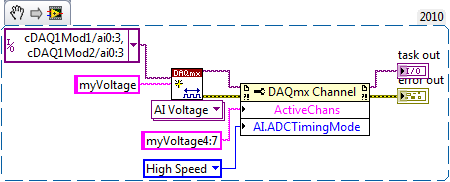
For example, the following code snippet creates 8 virtual channels named myVoltage0 by myVoltage7 and sets HAVE them. ADCTimingMode on myVoltage4 of virtual channels through myVoltage7. These are in the cDAQ1Mod2/ai0 physical channels via cDAQ1Mod2/ai3:
If you leave off of the entry "name" on the string to create VI, then the virtual channel names are the same as the names of physical channel, so it's the equivalent:
And by the way, a right-click on the property and selecting "create > Constant ' context menu saves you from having to hardcode a number like 14712.
Brad
-
Meter in a loop and read reduced sampling rate
Chassis: 9188
AI: 9219
CI: 9401
As pictured, without reading of CI, I can adjust the sampling rate of metered software. But reading of CI, the maximum rate is around 5 Hz. I already changed 9219 high-resolution property to high speed. What is the problem?
Hi, Carlos, thanks for your response. I acutally has solved this problem by using the connection series I and CI (i.e. connect error off HAVE error in the CI) but not parallel as the pic shows.
-
6255 sampling rate causes the dc offset
I see a dc offset in the measures of analog input I select different sampling frequencies.
I have USB-6255 (mass termination) multifunction data acquisition and I use measurement and Automation Explorer to put in place my entries.
My raw analog input is-0, 6250 volts dc, I have set up a task that uses 4 differential channels with no custom scale.
I have defined the scope of the input signal to +/-0 .8v for you sure I get good resolution.
Acquisition mode is continuous, samples of read is 1 k and I play with the order of 10kS/s rates 50kS/s.
While this task runs in the MAX, I can put my cursor in the rate field and use the top and down arrow keys to change the sampling frequency. As I do, I can see the light changes reported as much as 150 MV rate from one to the other.
It is a significant change when the total time of entry is lower to +/-1v.
The direction of movement is independent of the increase or decrease of the sampling frequency.
For example,.
23kS/s, the declared value is - 0.540v,
24kS/s, she moves to-0.620v.
25kS/s, she moves to-0.690v.
26kS/s, she moves back to-0665v.
27kS/s, she moves back to-0.625v.
and 28kS/s, she moves to - 0.535v.
At first, I thought that the sampling change made a change of the input impedance and change the load on my source, however, all the time, my dc signal source remained at the - 0.625v (as measured with a multimeter fluke at the connection point to data acquisition).
Why this is happening and what can I do about it? I want to give my users the ability to choose their desired sampling frequency.
My guess is that I need to add an amplifier to fixed gain with a gain of 5 to 10 to make the input signal to use the maximum of the analog input level (+ / 10v).
I use MAX version 5.0.0f1
Thanks for any help,
Tobin
Hi Tobin,
What do you use to generate the signal-. 625 volt? If you are using a switching power supply, you can experience aliasing where the power supply is turned on and stop.
In addition, are see you the same tensions at the same sampling rate? See you always - .540v to 23kS/s or vary over time?
Finally, you have a second 6255 you can try to replicate this on? It could be that the unit is defective.
N


Maybe you are looking for
-
I had a problem trying to port before my PS4. I have the extreme of apple and have created a static ip address, then I went and entered the UDP and TCP as follows: TCP: 80, 443, 3478, 3479, 3480 UDP: 3478, 3479 But next to the TCP, I get the message
-
The message send failed.There was an error of fixing call_skype_logo.png. Please check if you have access to the file.
-
I always use firefox browser and I recently had a broblem sirious in FF, I'm getting too many popups and ads in ff. I try to remove them, but I can't succeed. I don't know how to solve this problem. I have to check Control Panel to check there is no
-
Attuatori valvole e serrande - actuator
Salvo, nell ambito di a progetto di una camera revises mi trovo a dover pilotare e serrande valvole has life in modo da poter Mio desiderate all dell ambiente interno di terms (temperatura, umidita) set point. Sulla base delle mie knowledge, penso ch
-
When I try to open the Windvd bd is not open or play DVDs. A Vista is my operating system.