NI USB-6009 digital outputs are active when connected to a PC - I'm not that
I have a small problem:
All outputs digital NI USB-6009 module become active when the module is connected to a PC when no VI is running.
As soon as I start my VI, which controls the module, all the outputs are disabled (now inactive).
How can I achieve this, outputs are inactive if the module is connected to a PC with no program running?
johanneshoer wrote:
I have a small problem:
All outputs digital NI USB-6009 module become active when the module is connected to a PC when no VI is running.
As soon as I start my VI, which controls the module, all the outputs are disabled (now inactive).
How can I achieve this, outputs are inactive if the module is connected to a PC with no program running?
The USB-6008/6009 case has a pull-up internal (4.7 kOhm) resistance. This causes the outputs digital on the device to have a startup logic high State. t is not recommended to use some sort of resistance of menu drop-down. However, what you can do is add octal buffer like the 74HC541 stamp and a digital output to control the sorting of the 74hc541 state mode. Connect the OAS and CEO input signal. A Summit on the pins of the latter will be sorting the output of the buffer State. Therefore, no output signal will be present until you pull the stems of low control. The USB-6008/6009 case have a 5 volt output (200mA max), you can use the buffer.
Tags: NI Software
Similar Questions
-
Pull-up external USB-6009. digital output (open collector) allows onboard external + 2.5 V output?
Pull-up external USB-6009. digital output (open collector) allows onboard external + 2.5 V output?
Hello
I want to config output digital USB-6009 to + 2.5 V above and 0 V digital output low. I know I can config USB-6009 digital output open collector with resistance to pull-up external, that can be applied with + 2.5 V power source.
My question is: can I use USB-6009 Board + 2.5 V output as the current source of resistance to pull-up? What resistance is a good number for the resistance to pull-up, if I can use this configuration?
Thank you much for the help.
Cathy
Hi Cathy,.
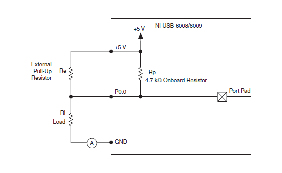
The digital USB 6008 front-end server looks like this:
So, there is actually an internal pullup to 5V 4.7 kOhm resistance when the device is configured to open collector.
If you want to display 0 to 2.5 V, I would look in a resistance of polarization of 4.7 kOhm between c and ground (according to the rest of your tour).
Best regards
-
USB-6009 slow output signals using SignalExpress - error 200077
We have a Council of USB-6009 and Signal Express version 3.5.0
We want to generate low-frequency, analog and digital outputs to simulate some slow movement process.
We have created the signals and their generated as output, put when we RUN the project, we get error 200077, which seems to indicate that we must use On Demand distribution of signals.
If we choose On Demand, then the generate DAQmx says we have a missing entry.
So, what method should be used with the slow USB-6009 to generate box (.01Hz and slower) analog and digital outputs?
These are 2 of the projects, we tried - using On Demand, N samples, continuous, internal, and external triggering etc..
Thanks adavance for your help...
Welcome to the forums of Steve,
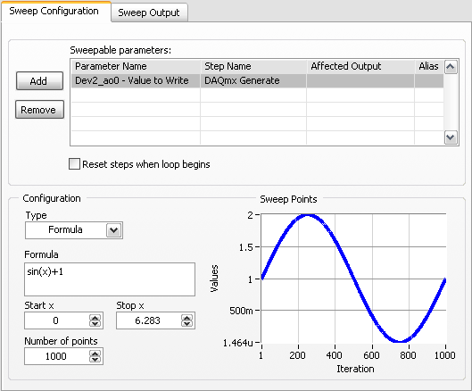
I have good news for you. I played a bit with the sweep and actually got a code facing up to generate a slow signal. I went and tested it with the 6009 and he was able to run without any errors. I joined here, but if you have to open (or anyone else in the future), here are some screenshots of how it works. If this works, feel free to make the forum as resolved while others can locate a solution a little easier in the future.
Scan Configuration:
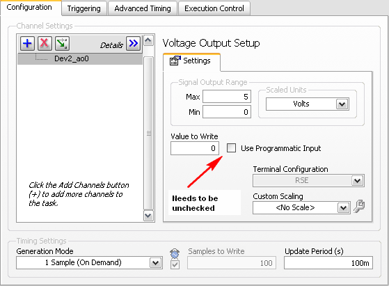
DAQmx Config:
-
NI USB-6501 digital output problem
Hello
I use DASYLab v.11 and I'm working on an interface with the NI USB-6501 where I'm putting a digital high on four ports.
With the module "NOR-DAQmx - digital input", I managed to read the digital inputs of the ' NI USB-6501 ".»
It's only the "NOR-DAQmx - digital output" I can't go to work.
Using 'NI MAX' of NOR I have easily can emmit my four LEDs in the way of my High/Low ports.
But not with DASYLab. When you use DASYLab tension on the ports remains unchanged.
Now, I have a switch module, generating 5/0, directly connected to the digital output module, which is assigned to my four output ports for my task.
I also tried with a module of relay between the two without success. I also tried to use 1.5 above instead of 5 without success.
I use the option 'Bus (0/5 supply) for the module "Digital output".
"NI Max", I configured the ports as "active drive.
Any suggestion of what I might be missing?
Thank you
Martin
Hmm, four ports, or four lines?
A port consists of eight lines. Each line can control an LED (ON / OFF ~ 0/5V).
If you have created a task to dig-out to control a port, 5V to this port sending sets all lines of this port to 'high '.
You need to 255 for each line one too high port (at the bit level: 128 + 64 + 32 + 16 + 8 + 4 + 2 + 1).<- eight="">
Or, you can create a dig out tasks to control four lines of a specific port.
Four lanes of the EEG DAQmx DigOut module.
Each of the channels of the modul will feed a single line of the task/device.
Four switches will then turn the lights, or turn off.
Make sure, that the 'bitposition' is the number of correct line (see picture).
-
USB 6008 digital output signal
I am VERY new to LabView and have been racking my brain trying to get digital output of my USB-6008. All I want is to be able to get a signal of + 5 V of my digital output when I click on a button. This signal opens a valve on a system I see so when it is pressed, it must stay open until I press the new button. It seems simple enough to me, but I'm not too familiar with LabView. Help, please!
Stripling07
You must first take the LabVIEW tutorials and then look at the links to get started with DAQmx .
The simplest program would be with the DAQ Assistant. Drop it on your schema, and then select digital output > digital line. Select the line when the wizard has completed, click OK. Wire a Boolean value in a table to build and the output of which is connected to the data entry. That's all. You can test the output of MAX (Measurement & Automation Explorer) with the test Panel. Do NOT test with your connected tap. Your valve may require more current that can provide the 6008.

-
USB-6211 - digital output not supported?
Hi all
I can't use the USB6211 device port... I use daqmx with Delphi7 API functions.
First of all, I tried this:
DAQmxCreateTask('', @TaskDO);
DAQmxCreateDOChan (TaskDO, PChar('Dev1/port0'), ", DAQmx_Val_ChanForAllLines);
DAQmxWriteDigitalU8 (TaskDO, 1, 1, 1, DAQmx_Val_GroupByChannel, $FF, @written, nil);I had an error in the DAQmxWriteDigitalU8:-200012 (= digital output not supported). (???)
OK, I tried to disable autostart option based on DAQmxWriteDigitalU8 and insert a 'manual' start in the code:
DAQmxCreateTask('', @TaskDO);
DAQmxCreateDOChan (TaskDO, PChar('Dev1/port0'), ", DAQmx_Val_ChanForAllLines);
DAQmxStartTask (TaskDO);
DAQmxWriteDigitalU8 (TaskDO, 1, 0, 1, DAQmx_Val_GroupByChannel, $FF, @written, nil);
DAQmxStopTask (TaskDO);Now, I got the same error in DAQmxStartTask:-200012 (Digital Output not supported, once again). (?????)
I don't understand.. 'Digital output not supported "? USB-6211 has 4 lines! What is the problem?
I want to just turn on and off the lines from code...
-Cs George-
Well, finally I figured out...

Here is the solution:
DAQmxCreateTask('', @TaskDO);
DAQmxCreateDOChan (TaskDO, PChar('Dev1/port1'), ", DAQmx_Val_ChanForAllLines);
DAQmxWriteDigitalU8 (TaskDO, 1, @dummy, 1, DAQmx_Val_GroupByChannel, @bitmask, @written, nil);Digital output lines are on port1! Corrected parameter.
And the part of the interface of DAQmxWriteDigitalU8 had to be changed (in nidaqmx.pas).
I don't know why, but the AutoStart (dummy) parameter in the DAQmxWriteDigitalU8 function is ignored: function always starts task automatically, regardless of the value of autostart. But this isn't a problem for me.-Cs George-
-
USB-6289 digital output signals setting
I use a USB-6289. I am writing a CVI application that uses this device. I need to put the digital i/o pins as outputs. In the CVI app, I know I can create these tasks with the tools-> create/edit DAQmx tasks. He created this:
Int32 CreateDAQTaskInProject(TaskHandle *taskOut1)
{
Int32 DAQmxError = DAQmxSuccess;
TaskHandle taskOut;DAQmxErrChk (DAQmxCreateTask ("DAQTaskInProject", & taskOut));
DAQmxErrChk (DAQmxCreateDOChan (taskOut, "USB-6289/port0", "))
"DigitalOut", DAQmx_Val_ChanForAllLines));
DAQmxErrChk (DAQmxSetChanAttribute (taskOut, "DigitalOut", DAQmx_DO_InvertLines, 0));* taskOut1 = taskOut;
Error:
Return DAQmxError;
}So this it puts in place but not to write the data. My question is what is the command to write the data?
Also I was wondering if the code source of any example that shows how these commands are made? Is it possible to configure the bits individually? I only need to use 5 of these pins as outputs so t would be coll if I could write that the bits D0 - D4.
Are there documents written on these commands and how they are used?
Thanks in advance
A DAQmxWrite writes the data.
Go to help > examples > material input and output > DAQmx > digital generation.
If you specify the lines instead of a port, you can use as the number of bits you want.
First glance using the ICB.
-
Error writing to usb-6343 digital output
Hello...
I have a trask to produce some digital waves... so I use usb daq-6343. to start, I am writing 1 simple value (i.e., 1) to the first pin of the port. but I get the error here, I enclose error png and part vi of the code... Please help me here...
Thanks & best regards,
-
OnPlus MY port LED not always turned on/active when connected
I noticed that the port of LUN is not still active despite being connected.
The port will go completely dead where even a powercycle of the ON100 will not activate the port (eth1 on the device I believe based on of NTOP poster config). The switch (SLM2008 - v2.0.0.10) show that no device is connected and by moving the ON100 on one another well known port will always appear also died. Sometimes to put the ports will cause the next LUN interface to life, but not always.
When it works I have no problem using the mirroring port SLM2008 had with NTOP for obtaining all the expected data however I can't quite trust this configuration yet due to the interface of MY not being always active.
Suggestions?
Other than that and a few strange bugs listed in May the release notes I hit, I'm really loving this service despite the lack of support from RV220W (I hope it's in the works of Cisco / the TeamF1 show the).
Michael - I assume that you have already tried to replace the cable also?
-
Why are the boundaries of the layer or layer groups not that of the document?
Why are assets the whole layer or a layer group rather than be only clipped on the canvas, I'm working on that?
The limits of a resulting asset layer or layer group are all of the area occupied by the pixels of the layer or layer group. This is how the underlying infrastructure Adobe generator works. We are studying the feasibility of changing this behaviour. If you want it changed, please let us know here!
If you want to restrict to the linked document, apply a layer mask that écrêtera layers and groups of layers that extend beyond the limits of the document.
-
More and more common digital output on USB-6001 with ULN2003A
I am ordering an engine step by step and the current required on the digital inputs of the stepper driver is close to 11mA (at 5V). My USB-6001 is not capable of producing this high current. I've seen people using the ULN2003A to control relay and it looks like it should work for my application. It will work and then I use the 5V output to go to the ULN2003A because it can produce for a 150mA. To associate the ULN2003A I use the 5V output and put the positive on the COM?
As you drew it should be fine. Do not connect data acquisition + 5 V because the controller inputs are opto-isolated. That circuit is also compatible with the 11 current requirement my mentioned in your first post.
USB-6001 digital lines are software timed so your maximum stage rates will be very high.
Lynn
-
Synchronization features 2 usb-6009 - please help
Hello
I'm trying to simultaneously capture data from 2 devices usb-6009. I've implemented the two Renault as follows.
1. using a function generator, generate a sine wave, which is slower and not a multiple of the sampling notes (48 kHz) and apply it on the odd numbered tracks.
2. connect the pairs of channels on the ground.
3. connect the PFI0 to a digital output of one of the Renault.
4. implement each DAQ sample faster (48 kHz) as possible and trigger off the coast of PFI0 entry.
5 generate the shutter of digital output - software write to 'Dev1/port0.
6. read samples that result and determine the difference between each of the odd channels between the Renault in a given set sample.
My results are not as expected. Use Excel to plot the data, I see that the Renault 2 data are staggered on each set of sampling.
I checked on the scope that the trigger works and that both got triggered. I think that the configuration above is not complete and I think I need to
Configure the two Renault to share the same clock source, but I don't know how to set up 2 Renault to share the same clock. My questions are
(1) exceeds my setup ok?
(2) If you need to configure 2 Renault share the same clock, how to put in place?
(3) is it possible sync 2 devices usb-6009?
Thank you
Tuan
Your above configuration seems correct.
The method that you use to synchronize two devices is the best you can get. The PFI line can only read in a trigger or a counter of entry. You cannot use to import a sample clock. Each 6009 must use its own on-board clock.
Typically, if you really want to sinchronize both acquisitions you must share a sampling and a trigger to start clock. Here, we are only able to share a departure with the PFI line trigger (such as material prevents you from sharing the clock) and let the individual clocks govern the actual acquisition is simply not possible really to synchronize two 6009 s and you're doing the best you can.
Corn
-
OR USB-6009 can produce the constant current source/sink?
Hi all
I have a card NI USB DAQ to 6009. I need a battery for constant (charge/discharge current<1mA) and="" simultaneously="" monitor="" its="">
I was wondering if I can use USB-6009 of output constant source/sink of charge/discharge current the battery? I've seen a few threads that says 6009 impossible to output constant son of currents, but other says we can use the digital output to provide the current, but it was not only described how.
Thank you.
All the outputs of the USB-6009 case are sources of tension and all have current limits low. There is no way to generate outputs current controlled directly from this device.
What I would do (and have done) is to build circuits of external current source/sink with an op amp or a transistor and allows you to enable or disable a digital output of the USB-6009. If the current must be adjustable, use an op amp circuit that takes an input of the analog output of the USB-6009 voltage to set the current. Use an analog input channel to monitor the battery voltage.
Lynn
-
Hello
I am trying to learn labVIEW DAQ and right now I'm trying to understand how to use NI 9474 with labview. NEITHER 9474 is a device with digital outputs. I am attaching a (badly drawn) diagram of how I have my real wired circuit. For some reason, the voltage at the terminals of the resistance is 9v instead what that either the digital output should be when I put assistant daq for 1 sample on request. When I change to continuous samples daq assistant, it reads 4.6v. So I wonder what am I doing wrong and what should my digital output be?
I've attached my vi file, if someone can you please help me understand how to use NI 9474 with labview?
-
Acquiring bipolar signals NI DAQ USB 6009
Hello
The NI DAQ USB 6009 case is capable of acquiring biploar waveform? I have a signal generator that provides a 0.5V wave triangular amplitude in the NI DAQ USB 6009. The NOR-DAQ is connected to LABView and acquire signals using the LabVIEW express vi. The waveform that appears is unipolar. Terminal configuration is set to differential. Is the waveform which is seen. Thank you. Mary
Hi Tupaj,
See a voltage floating as this can sometimes be the result of a measure badly grounded. It would be useful, like Dennis, to know how you have this wired up. Please take a look at this guide to make sure that the device is properly connected to Earth:
Field wiring and analog noise - http://www.ni.com/white-paper/3344/en
In addition, information about the configuration of your software are also important. Here's an example of how implementing a fundamental mission of analog input for your 6009:
Video installation instructions - http://www.ni.com/swf/devzone/ai/
The example Finder has also several screws that already do it for you. If you work in 2012 before LabVIEW, look for Acq Cont & chart voltage-Int of the Clk.vi in the Finder of the example. LabVIEW 2012 will have a similar named VI voltage - Software-Timed Input.vi.
Kind regards
Maybe you are looking for
-
CP is 100% with Win 2 k, 9.0 is worse than 4.0, Flashblock?
CP is 100%, which means that it is maxed out poor performanceWin 2 k is the operating system9.0 seems to be the worst performer4.0 tops out at 100, but not as oftenResearch shows increased ads and hurt nonessential generals, something related to a "F
-
Question from standby/hibernation on Portege M400(3G) after update BIOS 3.50
After installing 3.50 BIOS update, the machine stopped to switch to manual mode of sleep. He begins to enter standby mode, the screen turns off, switches of the computer during approximately 5 seconds with power led to go off and then restarts. After
-
DVD - RW for Satellite 2800-500: IDE1 error, disk not recognized
Installation of a slim drive DVD - RW NEC ND6500 caused a message "Error IDE1" at startup and the drive was not recognized.The DVD-RW Toshiba SD - R6472 drive is not compatible with my Satellite 2800-500?Does anyone know a way to make someone of them
-
Safari, when I return to the page, freeze a few seconds. At the same time I can't scroll For example, in chrome, this is not present, and it's sad Thanks in advance for your help
-
Hello world I recently bought the new lenovo laptop Y580, and I have a question that I couldn't find the answer to. I was wondering what is the connection speed for the mSATA slot. I know that the normal SATA hard drive connection is 3 Gbit/s, but I