niScope acquisition surveyed EX: simple taking the pulse?
I built an application scope of rather useful digital storage around the Acquisition of respondents that NEITHER furniture.
My problem is that I can't capture a single pulse by a lamp circuit. The vi always re triggers the worst
time and erases the original trace. Y at - it a simple way to implement a unique trace as the soft Front mode
Application of Panel?
Koutcheens
Dan.
Unfortunately, I'm doing rather poorly on the logic statements. If it wasn't for the fact that LabView is so user friendly, I couldn't
program at all. Since LV 5.1 I used the method "institutionalised blind squirrell finds a nut" with never decrease
results. I've attached a screenshot of the best that I could understand your explanation. Of course, I missed something.
Koutcheens
Tags: NI Products
Similar Questions
-
-Measurement of the pulse width specifies the timeout?
I'm trying to set up a simple project of Signal Express that measure the pulse of two separate signal lines width.
My PCI6224 has two entrances of meter and then run each pulse in the entrance of a meter line, respectively.
The I set up the express project signal attached, which consists of two simultaneously runnings tasks DAQmxAcquire. Each of them is set to measure the pulse for one of the pulse width. I then connect the results for further analysis.
This configuration works very well from time to time. The problem arises when the impulses do not arrive quickly enough and the acquisition of the timeout action. Looks like that has a simple solution - just increase the time-out - but I can't find a single setting around the affects, the time-out! The time-out period is always 10 seconds, regardless of what I do.
Can anyone help?
Thank you.
Hello rothloup,
Unfortunately, there is no option to change the time-out Signal Express for a task entry counter. This has been brought to the attention of our developers.
Reading a DAQmx LabVIEW VI has a time-out node you can specify the time-out period, even in the tasks of meter. I suggest you try to implement your system in LabVIEW (if you can).
Here is a tutorial on how to make PWM in LabVIEW.
http://www.NI.com/Tutorial/2991/en/
See you soon,.
-
Hello
Installation program:
2 x PCI-6602
Configuration:
Sampling the five PWM signals of 50 kHz using five counters (2 on a map) and three on another for about 10-15 seconds by recording continuously.
All meter tasks are configured for DMA transfer.
Problem:
I get 200141 errors from time to time.
Question:
I tried to increase the size of buffer and all tasks of meter are set to DMA. In the error message the last suggestion is to "divide the input signal before taking the action. I don't understand this suggestion. What is meant by "split the signal before taking the action?
I am open to other solutions to the problem.
/Mola
Yes, I know that the 2 MB/s sound do not like much, but it's a way of high load very low tolerance to try to get 2 MB/s. You have 5 DMA controllers to negotiate access to the bus and each transmits only 1 or 2 samples of 32-bit whenever he gets access.
I've seen published baseline data where the maximum sustained rate was< 1="" million/sec="" (don't="" recall="" if="" it="" was="" mbytes="" or="" msamples). ="" as="" i="" recall,="" finite="" acquisition="" mode="" allowed="" higher="" rates="" for="" shorter="">
Ah yes, here is a link that leads to the other links. See the section on "The counter of the FIFO" in the first message. Do you see a * very * significant difference in the performance of the M series for the series X-series. Here are data for counters of the E series. (It is fair to note that the comparative analysis was conducted with a much older PC hardware). For the 6602 counter chip was designed between E- and M-series series, so you can probably expect performance in-between.
Also note that the benchmarks seem to have been done with a task of window unique tent of owning all the bandwidth PCI as possible. Since you would have 5 tasks they negotiate access, you lose definitely even more overhead. In addition, for fair comparisons, your 50 kHz PWM would act as a measure of 100 kHz since you have 2 semiperiods to DAB per cycle of 50 kHz.
Now that I've seen benchmarks once again, I am convinced that it is a no-go for you with just the 6602. The good news is that the series X-series seem able to yet more ridiculously than I remembered.
-Kevin P
-
Retrigger encoder and acquisition of analog input on the spur of Z?
I have a card PCI-6232 and use THIS angular Encoder on the counter 1 to provide a base mean angle for Internet high speed (50-100 kHz) measures the analog voltage. I use a period of CI on counter 2 to measure the duration of the impulse of Z to determine the length of each measure. It kinda works, but the result is somewhat contradictory. I get about 1 in three cycles without encoder data. I need to find a way to trigger the acquisition to record data for each cycle trigger on the pulse of Z. If you know another way to do this I'd be open to that as well. Thank you, Steve
Hi Sara,.
Thanks for your reply. What I wanted to do was to trigger an analysis of the encoder and an entry at the same time triggering the pulse of z analog encoder. It took a lot of digging through similar samples and after a week of fighting, I thought about it tonight. I'll post this once I clean up the mess. Problem solved thanks to dozens of you ad info and samples!
-
at the same time production and measuring the pulse
Hello everyone,
I'm generates a pulse for specific time. Now, I want to measure within the same daq card. I've done Vi for him but he has an error. I have USB daq-6343. I enclose my Vi here.
The problem is I am able to get pulses generated at PIN 6 PFI but reading Vi watch time-out error.
I plugged the wire between PFI 1 pin and PFI 6 pins on the DAQ card.
So please suggest me what to do to eliminate this error.
Thanks & best regards,
I just looked at your original vi, I had looked only at the most distant (corrected) a previously. I don't see a good reason to read timeout error you have immediately. Record of an error timeout on your attempt reading suggests that the code was executed without error so far, including the beginning of the generation of pulses. That would leave wondering on physical cable connection or possibly some undesirable side effects caused by your cleanup code when you three States a PFI lines.
The other issue was my suggestion to leave DAQmx Timing.vi outside of the configuration string entirely for cases like this where you only want to build a single pulse. To be honest, it's a habit & practice I adopted a long time ago. I thought one of the reasons was that the finished pulse trains required a minimum of 2 samples. A bit of test code showed me that it isn't true, if my memory tells me there was a time when it * used * to be true. I don't remember if I have errors or if the task has chosen to generate 2 pulses with just a warning, or something. I just remember that, while he was working on a module that was supposed to be able to produce any number of pulses from 1 to N, I found that I wasn't actually able to support the case of 1 pulse by asking just 1 sample over sample mode.
* Anyway *, the other reason to avoid sampling over for a single pulse mode is that in the past, this would consume actually 2 counters on DAQ cards. Generated the pulse (s) while the other was a help that triggered the first to control the number of generated pulses. It was unnecessary as you could * also * generate a single pulse leaving the DAQmx Timing.vi out of the config, a method that used only 1 meter.
X-series cards (like yours) don't consume over 2 programmable counters of the user to generate finite pulse trains, so the lesson I learned a long time ago and was trying to convey is perhaps not so important in your case. I recommend it even if you know that you will always generate a single pulse, simply because he considered the standard way to generate a single pulse (as seen in examples of navigation).
-Kevin P
-
VI to convert input signals NI 9402 in a RPM value, based on the frequency of the pulses
Hello
I'm looking for a VI convert an input signal NI 9402 in a RPM value, based on the frequency of the pulses. Is there such a thing that exists in the library of national instruments?
I run LAbview 2014 integrated control and monitoring on on a cRIO 9802 high performance integrated system with NEITHER 9402, 4 channels, 50 LV, LV TTL Module input/output digital, ultra high speed digital i/o for the cRIO module.
Any help would be greatly appreciated.
The easiest way is to use the FPGA to get the time between the edges of your pulse increase (shift registers to maintain the current situation and the time will be necessary). This will give you the period. If it's a single pulse per turn, then the number of laps is just 60/T, where T is the time in seconds.
-
Measure the frequency of the pulses PXI-6624
Hello. I work with a PXI-6624 and am interested to make measurements of pulsed frequency for frequency and duty cycle on its inputs using DAQmx.
When I go to create the virtual channel, however, I have error-200431:
"Physical channel selected does not support the type of measure required by the virtual channel you create."
' Asked the value: pulse frequency.
«You can select: frequency, period, pulse width, period of Semi, separation of the two edges, Position:...» »
Is this card really not capable of doing these measures of pulse frequency?
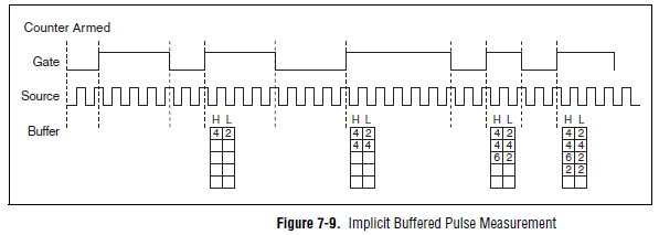
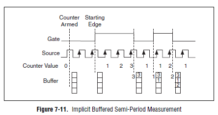
Yes, the "Pulse" (not to be confused with "Pulse Width") measure was introduced with STC3 of OR including CompactDAQ and X series devices.
Measuring the pulse:
However, you should always be able to measure the frequency and the duty cycle on your card with a half measure:
The half measure:
The images are in the X Series user manual.
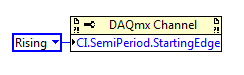
The difference between these two modes boils down to how the data is stored and implemented in buffer on the map - with the period semi method that the material does not distinguish between high and low samples and puts everything in a single buffer. However, if you start the meter on the song (see below the node property), then you would know the order of low and high samples in software, and are easy enough to calculate cycle frequency and the duty of this.
Best regards
-
Salvation;
Here is the solution for your problem.
The cause is that "Gen dig Pulse Train-Finite" uses Ctr0 both Ctr1.
Please refer to:
"When you do a finite pulse train generation, a counter generates pulse train, and the other counter generates an impulse that acts as a barrier to the first counter. If you change the pulse train to generate continuously or
only generate a pulse, you can run two tasks of meter at the same time without error. »
http://digital.NI.com/public.nsf/allkb/04BEDD9E9E91ED3486256D180048116D
I used Ctr0 and Ctr2, jumping Ctr1 as it is reserved by "" Gen dig Pulse Train-Finite ". I works very well.
Kizito.
-
Count the number of 1 is present in digital waveforms obtained by converting the pulse signals.
Hello
I use Analogtodigital.Vi to convert the pulse of the sequences in digital.signals.I am able to get the representation of digital waveforms of impulses.
But how to count the number of 1 is present in the converted digital waveform. I want to count the number of 1 is present in the digital waveform converted.
Thanks in advance.
Have you tried the block scheme of similar to the Digital.vi of opening?
It creates an array 2D uncompressed 1 and 0, which is the binary 16 bits A/D conversion of each element in the array Y of the input waveform. You can use the DWDT digital Array.vi Boolean to convert a 2D Boolean table. Then convert Boolean values to 1.0 and summarize the array of integers. The sum must be the number of 1 bits in the digital waveforms.
Lynn
Note: The VI attached is saved in version 8.6. When I have it saved for the previous Version a warning was generated about the possible differences in the versions. Let me know if it doesn't work, and you are using which version of LV.
-
How to count the pulses using RIO (FPGA)
Hello
I want to use RIO (FPGA) for counting the pulses produced by a sensor,
but I don't know how to program. can someone help me.
Thanks in advance
CAIX wrote:
Hello
I want to use RIO (FPGA) for counting the pulses produced by a sensor,
but I don't know how to program. can someone help me.
Thanks in advance
Search for example for 'Meter of RIO' finder. There are dozens of examples that should help you.
-
How to run a window of data acquisition and another pane at the same time
Hello
I have a main window for data acquisition and in front panel there are four Sub Vi. When the main window of data acquisition is running and at the same time if I run the Subvi - main window stops data acquisition and the secondary window starts to run. But I want to launch the window of acquisition of primary data and the pane at the same time. Please give me a solution for this...
Thanking in advance.
Nikhil
Hi Nikhil,
My explanation has answered your question. Take a look at the image as an attachment. Let us know if you have any other questions.
-
Looking for model/data format to import survey data in the survey on demand in the apex 4.2.5
Hello
Looking for a model/data format to import survey data in the survey on demand in the apex 4.2.5.
Thank you
hayatms wrote:
Where I can get this CSV format, so I have to add in the file accordingly. Thank you
Click on the button create poll on the surveys page, then select the option to create a survey from a text file. An example of the required format is displayed. It is not a CSV format.
-
Hello, currently I have 3 subscribers: 1) first 2) effects after 3) package for a student in the acquisition of switching on all the programs. Can unsubscribe the first two presentations, namely, I want to unsubscribe from the first and Adobe Adobe after effect. user: [email protected]
Hello Anton
I checked your account and see that you had a first CC, After Effects CC & a full subscription of creative cloud.
I cancelled the subscription Premiere and After Effects for you.
Let me know if you need assistance.
Thank you
Scott
Follow us on Twitter @AdobeCare
-
Inaccurate statistics in application of the pulse
In particular, the heads of the displayed region seem to be off when I joined to my DataGrid with the application of pulses. All regions have the same number of entries (297779) in Pulse, if I ask the regions with applications I can see the exact number of each region (for example 0.11, 182715, 4981, 39845, 9958, 5, 4858, 204217, 35, 1). I can verify that these counts are correct since I am loading the records in a database. My datagrid is composed of three members of server with two locators. All regions are partitioned. Also, I am able to see all members with precision in the pulse, it seems to be configured correctly. Any idea on this?
Thank you
Tom
Tom,
There are a number of impulse of bugs regarding the data displayed incorrectly. What version do you use? The last patch available pulse is 7.0.0.1. If you're already on it, so you wait 7.0.1 which should be available in a week or two.
-Jens
-
I have the lessons created using Captivate using my high school students. I would like to the student taking the test type in their name and make it appear on the page of the score so that they can not share the results.
Otherwise, children can make these for HW and share with their friends.
Thank you
Moved Forum of cloud.
Maybe you are looking for
-
Firefox crashes on startup - occurs every time you start
It happens on every attempt to start. I tried too private browsing mode, it crashes as well. SAFE MODE CRASH-ID: bp-478a6514-09f7-474f-a560-1fd222120221
-
As above
-
Re: Satellite A300-1LT built in mic won't work
There is a problem with the microphone.It does not even if everything seems fine. I have the drivers updated, I put it in the Panel as default, is said here is work, when I plug another microphone (external), we're working, but this one isn't.It is n
-
I use to perform external calibration and adjustment on the module, PXI - 4070 FlexDMM Cal Exec 3.2.2. How to access the comments field to include additional information? Thank you!
-
Need help to add videos to my rocket
I got it for Christmas. I know how to add all my songs and pictures, but I can't add videos to it. Whenever I add a video in the video folder, I look on my rocket and he said either "Format file not supported" or it just does not appear on my rocket.