NOR-5133 slow measurement
Try to measure a signal which will be pulsated all Ms. right now I'm measuring and triggering off a pulse generator to simulate this signal; the generator is pulsed near 1 kHz, so that's fine. I noticed how slowly the program worked, in order to find the source that I gradually deleted almost everything outside the fair measurement and display of the waveform, and it is still too slow. It's hard to tell at first, look at the counter "pulse" - action of 40 to 100 ms/s aura 400ns. Of course repeat this measure has yet to significantly less than 1 ms, then. However, I look at the meter, it takes more of a second to get through 128 measures. No idea why this is the case? I have attached the VI which is clearly pretty rudimentary. With the threshold of declenchement.2 there is no case where the framework lacks a signal, because no error is thrown, and so I can really come up with any reason, apart from the speed of calculation for why this program cannot follow.
Thank you
Wolley
Tags: NI Software
Similar Questions
-
I don't see the icon of NOR-DAQmx in measurement window in Labview 2013 (student Edition)
Hi all:
I installed the driver NOR-DAQmx and Labview 2013 (Student Edition). I connected an acquisition of data NI USB-6008 and tested using NOR-DAQmx and that it works correctly.
Now, I tried to make registration of data of this device using the software Labview installed but as I open a new project and go to the block diagram and show the measure menu I can't NEITHER-DAQmx icon in the window (Menu) measurement in Labview 2013 (student Edition).
Any suggestion?
I enclose two screenshots.
Help, please.
Thank you
In what order did you install software?
You must install LabVIEW first, followed by DeviceDrivers!
-
Slow measure ca in application C++ with DMM-4065
The Soft Front Panel does not use niDMM_Read(), it uses niDMM_FetchMultiPoint(). The niDMM_ReadStatus() see you traced simply checks the size of the back of the measure and the status of the acquisition (running, completed late, finished without delay, etc.). It does not take a measure, that's why she returned much faster than FetchMultiPoint().
There are no special tricks to increase the speed of the Soft Front Panel. What you see tracks are real calls makes the driver.
If you are currently using niDMM_Read() in a loop, you should be able to increase your speed of measurement more further by opting to use niDMM_FetchMultiPoint() instead. Read() calls Initiate() and Abort(), which when you are able as fast as you are, can take up to a large percentage of your measurement time internally.
That said, the speed of your application will be highly dependent on your configuration - if you turn down your opening time, your quality will be reduced and depending on how accurate and precise, you need your measures, which may be unacceptable
-
Can I use a NOR-9244 for measuring single-phase AC 2-wire 480V?
As the 9244 module is rated for a maximum of 400 v L - N and L - L 800V, to measure 480V, I would need to connect to AI0 AI1 and let the neutral entry floating. Manual outlines all single phase measures referred to the input neutral and has some instructions on the conversion of L - N L - L measures, but it is expressed not bad so I don't know if it tells me that I can directly measure the voltage through AI0 AI1, or not.
Can anyone confirm that I can make measurements with 9244 cable in this configuration, until I drop the $$$ to buy it?
Hello MStewart,
A distinction must be made between Vpk and Vrms.
@GerdW is correct that the input device is ~ 1000Vpk (997.5Vpk). However, this translates into ~352.6 Vrms
The side of 800 Vrms for line (L - L) measures is for multiphase applications.
As you take a single-phase measure, you would use an AIx-neutral (L - N) connection.
The diagram for this is detailed in figure 12 on page 25 of the Manual:
<>http://www.NI.com/PDF/manuals/376131b.PDF >
So to measure above 400Vrms on this unit, you will need to use a power supply external to resign from the tension, as mentioned in the white paper in (specifically the section of voltage):
<>http://www.NI.com/white-paper/8198/en/ >
In summary the 9244 cannot directly measure 480Vrms. You can set before the signal to less than or equal to 400Vrms
I hope this helps to clarify your question!
See you soon,.
-ChristophersonJ
-
Hi Vjuno,
Thank you for your interest in Measurement Studio and NOR-IMAQ. Measurement Studio and NOR-Vision are separate software packages. If you are considering comes to acquire, save and display images from a camera IEEE our NI Vision Acquisition software located on our website (http://sine.ni.com/nips/cds/view/p/lang/en/nid/12892). If you want to set up a system of image analysis then you can buy the Module OR Vision Development, this includes NI Vision Acquisition (http://sine.ni.com/nips/cds/view/p/lang/en/nid/2881).
Thank you for your interest in our products!
Eric Reid
-
Hi all
I use USB-5133 to measure voltages of both channels simultaneously. For this, I use the NO-SCOPE. The scope record measured as a DJ-file data. I need these files in Matlab, but I can't open them. What would be the easiest way to export and to open these data in Matlab?
Any help is greatly appreciated!
Joonas
I've never used Matlab, this will probably not be able to help much. However, NEITHER-HWS uses HDF5 1.4.4 version which was released around 2002 or 2003. The current version of HDF5 is 1.8.5. I think remember me some problems of compatibility with 1.4.4 but it has been a long time and I don't remember the details. Hdf5 recorded the version of the writer in the file to allow compatibility downstream, and the HDFView doesn't seem to have a problem with the file (I was able to trace the track without any problem in the Viewer). You may need to define a compatibility option in your read file. See your documentation.
Data, stored as an array of I8s, are one of the two places (there is only one copy of data, but it is related to two places):
wfm_group0 / vectors / vector0 / data
wfm_group0 / traces / trace0 / axis / data_vector / data
The coefficients of the scale for the data are stored in
wfm_group0 / traces / trace0 / axis / scale_coef
It is an array of point numbers floating 64-bit with shift first, followed by the scale factor (0,1,...).
Timing information in the attributes of the x axis:
absolute timestamp - wfm_group0 / traces / trace0 / axis / ref_time
first point against the benchmark of timestamp - wfm_group0 / traces / trace0 / x axis / start
vesting period - wfm_group0 / traces / trace0 / x axis / increment
Good luck. My apologies for not having more help.
-
A measure of speed high speed with encoder in quadrature and NI 9401 on cDaq
Greetings,
We use an encoder in quadrature with 360 pulses/turn on the tracks (track A and B) and no trace of Z to measure motor speed at startup. Data acquisition, we use a NI 9401 in 9178 cDaq chassis and a pc with LabVIEW. The problem is that the start-up period is relatively short (less than 1 second), during which we measure speed as precisely as possible. The speed range is from 0 to 10000 RPM.
What type of measurement method that you would recommend.
Here are a few methods that we have already tried:
-Measure with DAQmx CIFreq--> high frequency with 2 counters: speed measurement, but with a very big mistake (+ 166 RPM).
-CIFreq DAQmx--> wide range with 2 counters: good speed data but more slow measurement,
-CICntEdges DAQmx (counting separated the two lanes, speed conversion): very incoherent speed data.
Thanks in advance for your help.
Matej
I would definitely say a 4, the measure of a low freq called option with 1 meter. (Frankly, I've never been
fond of this name because it is useful for freqs much higher than what I expect most people think "low freq".) This
is the method that I almost * always * use for frequency of counter measures. It works really well to capture transitional
variations in speed.
10000 rpm and 360 cycles/rev, you are looking at a maximum frequency of 60 kHz. The frequency measurement mode 1 meter
There will be 80 MHz internal clock by encoder cycle edges, then you will get more than 1000 strokes per measure. The point
that means only 1 number of quantization errors, you can expect<>
Further, you can average overall, say, 10 samples to you give even better accuracy and you could still be a data capture
rate significantly higher than the probable bandwidth of your mechanical system. (The average would just clean the jitter and noise and would not
Hide answer true mechanical characteristics).
-Kevin P
-
lose the wi - fi connection. Help!
Tecra M2 (Windows XP Prof) constantly loses the connection with a wi - fi built-in (g). The speed is slower, slower (48, 36... 1) and finally the connection breaks. Utility Intel States that the laptop "is out of reach" (actually 2 metres of access point). Once it arrives, the only thing I have to do is to disable and enable the connection. It will immediately with 54Bps again.
Also inside the same room there is an old Tecra 8000 (Windows 2000) with PCMCIA card DWL-G650 + interrupt never, nor to slow down the speed of it. Does anyone know what the reason and how to survive?
Hi gal
Can you please tell me what wireless card you are using?
-
Connecting two pxi-2527 with NI Switch Executive
Hello world
I want to build a test equipment to measure the resistance of the wires. My stock of material contains two cards-MUX pxi-2527 and a pxi-4070 DMM. Each pxi-2527 is connected (via a TB-2627) of a cable harness of the 26 son (name of the harness "6YDA" and "6YDB", see photos).
The two beams is absolutely equal in the Assembly and naming (for example the sons are named from A to Z).
First of all, I want to set up a self test function. For this purpose an adapter was built to connect the two cables to driver.
The adapter connect cable A to the first harness with cable A second son, the first B b to the second and so on.
For the auto test, simply measure the resistance of adapted connections 26.
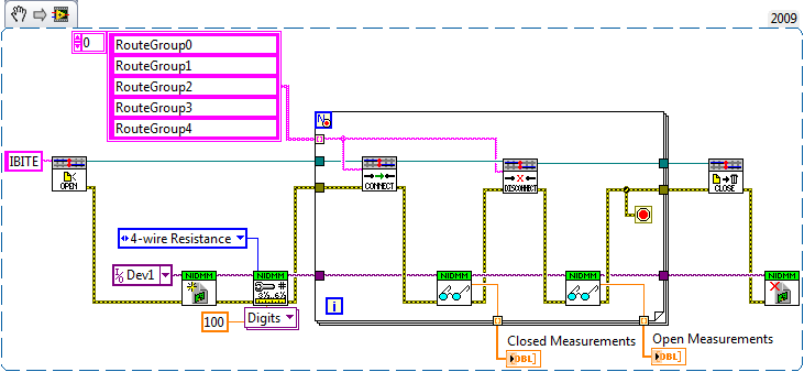
Now I tried to create a virtual device with roads and routegroups via Switch Executive and insert it in my LabView 2009 program.
But I m not sure if my virtual device is correct. (See pictures attached)
Unfortunately I have not found an example on the connection of two cards-MUX pxi-2527 together, I need your help.
I would be very happy to get help from you!
Thank you very much!
Greetings,
E Tec
Hi E-Tec,
Looks like you have already setup the roads and the routegroups in SwitchExecutive. Now let's launch LabVIEW and make some magic; Some examples of code that will test each routegroup:
The first thing we need to do is log on to your virtual device:
Then, you must configure our DMM and call certain route groups:
I made many assumptions on what we are trying to accomplish. My code does the following:
1. opening of the session for your named virtual device.
2. the opening of session for DMM... it has more parameters I have hidden for clarity. See DMM examples in help"Find examples | "" Material input and output"modular instruments and devices" NOR-DMM ' unique measures ' measure resistance if you want to see the entire feature set.
3 close your RouteGroups one at a time, measurement of resistance, opens the Routegroup, then measure resistance again. I put only the first 5 routegroups in this code.
Which should help you get started. Sorry to expect if a long time keep
 . Have a great day!
John Sullivan
Switch Product Support Engineer
National Instruments
-
Number of channels of "scan list" to decode
Is it possible to decode the number of channels in a scan list? The example of NOR (niSwitch Thermocouple Measurements.vi) that I use, requires the entry of "scan list" and "number of channels.
Hello Ddemara,
If you're multiplexing through a bunch of thermocouple, the scan list will be not complex, then we could easily write code to determine the number of channels. Our code will have to do the following:
(1) start a counter with the value 0.
(2) Iterate through scan list user-defined and add 1 to the counter whenever you find a comma. The last element will not have a comma, so we will need to add 1 to the value at the end.
(3) find each instance of a colon (":"), then find the two numbers on each side of the colon, subtract these two numbers and then add them to the value of the counter. We don't need to add one to the value of end here because we have already included the first item in the series
(4) the value of the counter is at this point the number of channels in the scan list.
If you have any questions to set this up, after. Have a great day!
FYI: The number of lanes in the example you mentioned allows us to recover data from the DMM as the first element of the array is always the thermocouple. If the number of channels is wrong, extract indexing element 0 will cause plug wrong value to the CJC for thermocouple input scaling of vi.
-
How to acquire data through several channels in parallel using E 6070 PXI, PXI-4071 and LabVIEW?
Hello
I use LabVIEW and NI PXI-4071 PXI NOR 6070E to measure the current through a variable resistance. Now, I use a single channel of SCB - 68, but I want to add another channel at the same time so that I can have two resistors instead of one that I cam measure current through them.
I have attached a Pdf file showing installation of equipment to use and code LabVIEW also.
Can someone look at these files and give me some guidelines or ideas that can help me solve this problem, please.
Thanks in advance.
Best regards
Shaheen.
Your 4071 can do a measure at a time. Your data acquisition cannot measure resistance is not she of the analog inputs.
However, you could use a multiplexer and multiplexer your 4071 DMM. This habit give you simultaneous action, but can acquire data one after the other, the speed depends on the multiplexer, you choose!
I hope this helps.
-
Difference between an instrument and DAQ hardware
Hello
I am very new to Labview and at this time I'm trying to grasp the concepts.
Can someone explain to me what is the difference between a DAQ hardware and an instrument (that we can control).
Also why they are placed in a different section in the palette function (measure I\O and Instrument I\O)?
João
In simple terms, hardware DAQ (measures of e/s) interface with NOR-DAQmx (or other drivers NEITHER as NOR-SCOPE) to measure, while the Instruments are often external to the computer and not rely on a computer to measure and use generally the VISA (or an abstraction of the VISA).
Instrument of e/s
http://zone.NI.com/reference/en-XX/help/371361K-01/lvmeasconcepts/instrument_i_o/
Measure IO
http://zone.NI.com/reference/en-XX/help/371361K-01/lvinstio/ni_meas_vis_func/
-
How the output voltage is coded on 16 bits DAQmx devices?
In our laboratory, we have two devices DAQmx, the NOR-PCIe-6363 and the NOR-PCI-6733. Both have 16-bit for bipolar analog output precision. I understand that the small voltage difference that can be made is 2 * Vref/2 ^ 16, where Vref is the reference AO voltage (10 Volts or externally provided for 6733, 10 or 5 Volts or externally supplied for the 6363).
I wanted to know how the output voltage is coded. DAQmx functions take 64 bit floats as input, and at some point, they must have their reduced accuracy. How is this done rounding, is a floating point around the nearest possible tension, or is always rounded down or always rounded upward?
What is all the possible output voltages? Some diagrams in NOR-DAQmx help/measurement Fundamentals, signals, Analog, sampling considerations seem like they could involve the maximum voltage + Vref is not achievable, so I think that is all of the possible tensions - Vref + 2 * Vref * n/2 ^ 16, with n ranging from 0 to 2 ^ 16-1 included. This includes - Vref and does not zero but + Vref.
Could I get confirmation on this point, or be corrected if it is wrong?
Hi Chris,
The scale of writing DAQmx version performs double floating precision scaling and then he made a turn, the closest to convert the resulting code of the DAC to double int16_t (or uint16_t for unipolar devices). Floating point scale includes the custom scale AO if you have configured one, the conversion of volts or AMPS to the codes of the DAC and for some devices, the calibration scale.
You can check the coefficients of scaling using the AO. Property of DevScalingCoeff. It takes V / A-> CAD codes and scaling into account calibration, but not the scales to customized AO.
The PCIe-6363 X series devices preset scaling in software. The internal reference of the AO is slightly higher than 10V, to correct the errors of gain and offset does not limit the output range. It also means that you are not limited to 9.9997 V on this device when you are using an internal reference.
The PCI-6733 uses calibration DAC instead of software scaling. RAW - 32768 means - 10 V, 0 corresponds to 0 V, 32768 is impossible because of two of the 16 bits of the add-in and 32767 translates 9.9997 V. When you continue 10 V to write DAQmx with this device, DAQmx he forced into 9.9997 V.
Note that for these two devices, the absolute accuracy full scale includes over 305 uV of error. Look at the tables of absolute precision AO in the specs of the device for the full story.
Brad
-
Hello.
I have problem with maximum sampling on USB - 6259 of NOR. I measure the hearts of rabbits EKG and I need to know, what maximum frequency can I sample this signal. I use 10 channels and I don't know if the maximum sampling frequency is for each channel or one. I know, I use the sampling rate 1 MECH. / s, but I don't know if MECH. / s means MHz I do need knowledge rate (frequency) Hz sampling. I know that USB - 6259 OR maximum sampling rate 1 ms/s, and 16 bits of resolution. This means 2 MB/s, but it is for each channel, but only one? Can I sample my signal with sampling rate 1 MHz theorist?
Thak much for your answers.
Since you have only a clock unique convert and the channels are multiplexed, by channel sampling frequency is the rate divided by the number of channels max. In your case, you would be sampling each 100kS/dry.
-
DAQmX does not appear in Labview 8.5
Story: Got fed up with Vista and downgraded to XP SP2. Reinstalled Labview, Measurement Studio, then DAQmX 9.4 (downloaded the last of the site NOR).
Measurement Studio seems to load DAQmX tasks correctly even though I'm scared to compile in the case where he trashes working hours. I have no reason to trust that he will not.
Just LabVIEW does not recognize DAQmX. It does not appear in the box tool. MEAS & Automation runs and talk to my USB-6212, so I guess that data acquisition drivers need to be installed and load correctly. But Labview... N/G. This version (DAQmX 9.4.0f1) is not compatible with the LV 8.5? I don't understand.
I uninstalled DAQmX & reinstalled with the same results (none). Help, please.
It seems that LV 8.5 tops on DAQmx version 9.3:
NOR-DAQ and LabVIEW (for Windows) version compatibility
Steve
Maybe you are looking for
-
I can't get farmville to load, been messed up since Friday, please help me
I updated adobe with no help, I nothing will load adobe keeps crashing
-
My tosh Saturday did not in service since yesterday. First of all, I left my laptop on while a few minutes and when I got home the only way to wake from sleep mode was to unplug the power cable. Then after and hour it did it again but this time he ha
-
Satellite A110 installs recovery disk but HARD DRIVE not displayed
Hi guys,. After searching the net, I finally found a forum in which I hope you can help me.I tried to search this forum for an answer but couldn't find him. I have a toshiba satellite a110-159, who, after a setback, did not start.CHKDSK discovered ma
-
My current router - Netgear N600 dual band 2.4 & 5 ghz. I tried to upgrade a ca router and my PC does not recognize it and I can't upgrade the software due to windows 10 saying the network firmware is up to date. I want to add the ca wireless router
-
Iconia A500 - abandonment to chance internet connection
I got this Acer Iconia A500 for quite awhile. I love this little tablet and never had a problem since the purchase. However, over the last 2 weeks, he started the Internet randomly-'No Internet Connection'. I can be in the same room as the router and