Nor-5406 & nor-5112 frequency sweep
Hello
I have a frequency generator (5406) that I use to generate a frequency sweep (1 ms by frequency).
When I read the signal with a digitizer (5112) it seems that the duration at each frequency is bad.
I've attached a photo (I hope) to identify the problem.
The sinus begins here, at a frequency of 20 kHz to 1710 (coordinates, left panel).
Because I taste 3 MHz and that each stage of the frequency is 1 ms, I expect to see the next step to 4710.
That is not the case (right panel)
Any help appreciated
Also attached to this message is a copy of a part of the block diagram.
Thank you
Hello
The explanation of what you see, is that even if you ar affecting your sample NOR-5112 3 ms/s, you are actually sampling at 3.03MS / s.
If you are referring to the specs of the device , you will notice that this Council has a maximum rate of 100MS/s of sampling and can sample at a rate decimated 100MS/s/n where n is an integer between 1 and 100e6. If the sampling frequency is not feasible by the digitizer, the pilot will force the value of the next achievable sampling frequency that is higher than what you asked. In this case n = 33 and your actual sampling rate is 3.03MS / s.
If by your calculation for 1ms, you will get 3000 samples at the rate of sampling or 3 ms/s. This would pass to 3030 samples at a rate of 3.03MS / s. I think that this corresponds to what you see on the image. To be certain of the current rate of your Board is sampling, try to use VI "niScope sampling rate" to query the actual sampling frequency of your digitizer.
-Jennifer O.
Tags: NI Products
Similar Questions
-
frequency sweep performance in the profile of stimulus Editor
Hi all
I am trying to understand what is the best way to do this.
I have an output signal. I want to start with a 5V signal, so I want to do it in a sine wave of amplitude of 0.05v starting at 1 Hz and gradually increase the Frequency, squirt up to 500 Hz. I know there is a sinusoidal wave function in the profile of stimulus Editor, but he seems to want to keep the fixed frequency.
Thank you.
There are a few options:
1. your own sinewave sequence that will sweep the frequency while he plays. The integrated sine wave function is just a sequence that you can view and copy edit however you want. Double click in the palette to view the sequence.
2 use multitasking and the sequence of the sinusoid built-in. The sequence of SineWave takes in a setting for the frequency, but it takes the value by reference. This means that if the value mapped to the frequency parameter changes so that the sine wave sequence runs, the frequency of the sine wave will update, too. This allows you to use a multi - load to run two parallel tasks: to call SineWave and one for the ramp of the frequency variable.
Attached, is an example to help you make sense of it. Maybe it's not the exact logic you want, but should help you get some ideas going. I hope this helps!
-
Hello
We need power RF amplifier with a function generator to create plasma in an ion source. The signal pulse duration must be 1ms long, repeated twice per second.
Today, we work in the following way: we spend the RF with f0 (aprox 1,995 MHz) frequency. After 20, we send a trigger signal passing frequency f1 (aprox 2.005 MHz). We keep this frequency for the rest of the pulse. However, the plasma that we generate is not 'constant' or stable during the whole impulse. If we smoothly change the frequency during the pulse we could improve.
We would like to do: use the frequency sweep: rather than use this frequency hopping, we would like to move smoothly f0 f1 (frequency scanning). Then F1 to f2.
As we have a PXI for data analysis, we believe using the arbitrary function generator of NOR: 5406 of NEITHER allowing the frequency sweep. However, in the book loads, it is not very clear, and I have a few questions:
-We can create a "list of frequencies. In the site OR below, it shows that the "minimum of Step' is 1.28us, which would be ok for us (I understand that the"minimum duration of Step"is the minimum time between 2 frequencies). However, the manual of the device "NI PXI/PCI-5402/5406 specifications" said the frequency list has a time step of 1 ms to 21s. What is the good?
-It is also said that the "duration of minimum list" is 1 s. For us, need us a shorter list that 0.5 seconds (we need to repeat the same pulse twice per second.). Is it possible to do what we want?
-At the end of the day, we would like to implement a control loop which modifies the list of frequencies in real-time.
http://zone.NI.com/reference/en-XX/help/370524L-01/nisignal_generators_help/features_by_device_smc/
Thanks for your help.
Best regards
Jose.Hi Jose,
You're right about the inconsistencies of the documentation. The minimum step was of 1 ms, but was changed to 1.28 µs to driver version 2.6. The help document has been modified to reflect that, but the specifications were not. I'll make sure that attaches.
The length of the minimum list is not listed in the book loads, and the latest version of the help the signal generators OR (driver version 2.9) lists the minimum list than the 1 step length. Aid has changed to the driver version 2.6.1 to clarify that the 1s meant 1 step. I've attached a screenshot of the help of the most recent.
There is an example that is installed with the NOR-FGEN driver called "Fgen Sweep Generator.vi". I would recommend from this for your application.
I hope that some of the inconsistencies in our documentation brightened. Please let us know if you have any other questions.
Elizabeth K.
Generators of signal produced technical support engineer
-
estimate the frequency of resonance sweeping the frequency of 100 Hz to 500 Hz
Hello
In fact, I need to make the open-loop system to vibrate the structure of 100 Hz to 500 Hz to find the resonant frequency. I tried to create the code that allows to operate (excited) structure and measure the fron of the sensor (capacitive sensor) signal. At first, I tested my code by generating the AI12 signal and connected this signal to the AO0 to evaluate the code. However, I have encountered two problems. first of all, the pulse in the acquisition of code (entry) signal is delayed by approximately 20ms as may be included as an attachment. Second, generating signal evolves each 0.01 s where start from 100 Hz to 500 Hz. in other words, at the beginning, I have a cycle and the cycle will increase at each 0.01 s. My question, how to calculate the FFT for each 0.01 s and at the end, showing the result on a graph to show the resonance frequency. Could you please help at this stage.
I have attached the file Vi.Khalid
Hi Khalid,
I'm glad that you found it useful. To add a frequency sweep, simply replace the uniform white noise vi with a beep that is located in the Signal Processing > signal generation > model Chirp.
I hope this helps. Good day.
-
PXI-5412 - discontinuities and dynamically modify the frequency with niFgen nodes of property
I'm trying to find a way to eliminate discontinuities and change frequency/amplitude on the fly. Is there a simple way to do this?
Basically, my ultimate goal is as so:
Table:
Start Stop Freq Freq dt
1 100 10
100 1000 5
1000-5000-10
When you start at 1, then move to 100 after 10 seconds. Then you would go from 100 to 1000 after 5 seconds. And finally, you would go from 1000 to 5000 in 10 seconds.
I use the niFgen Util creation frequency sweeping of data VI to create all the necessary frequencies.
I use nodes of property niFgen to try to achieve. I use a simple loop to move through a frequency table, and I update the frequency as follows:

I have everything set up and works, the only problem is that I have large discontinuous jumps whenever the frequency gets really changed. Unfortunately my oscilloscope are boring with the Print Screen function, so im trying to recreate using MS Paint:

Clearly not the best artist ever, but you can get the general idea. I get these discontinuities in the shape of V that are particularly sensitive to the peak of a wave.
Someone at - it a good suggestion on how I should go about it? I'll put in place the generation as follows:

Looks like you are using the operating mode Standard to do this, correct? The best way to go about this would be to use the frequency list mode, but the 5412 doesn't have this feature. I have seen documentation that the use of property with Standard function nodes can definitely cause these kinds of discontinuities. Another method is to use the arbitrary sequence mode, take a look at the niFgen "Arb Example.vi séquence" in the finder for example LabVIEW as a good reference on how to do this.
-
Change the frequency AO AO DC voltage scanning scan?
Hi all
I am very new to labview, but find the forums and examples extremely helpful. I probably spend 50 + hours to familiarize myself with tutorials and general information, but I am at a point where I need your help.
I'm unable to change the example "AO frequency sweep" found here (see custom_sweep_1.VI) to allow me to sweep the voltage. My instinct is that I don't need of the ' waveform buffer generation VI ' and that I should be able to remove the associated entries since I'm only interested in a sweep of DC voltage. It is also called create_log_frequencies.VI, and I'm fairly certain that I can use it as written and simply change "frequency", "tension". My work of the custom_sweep_1 changes are attached as custom_sweep_Voltage.
The problems I am having with the edition of custom_sweep_1 are:
(1) I don't think I understand very well how or if the parameters associated with waveform buffer generation VI relate to a sweep of DC voltage.
(2) an extension of 1): the loop depends on the samples and Cycles by buffer and I don't know how / whether to replace these values
(3) the .VI DAQmx Timing (sample clock) receives its sampling frequency of output waveform buffer generation VI, but I think I can use 1/scan time to replace this (?)
(4) the DAQmx Write.VI gets waveform buffer generation data, but if I can get around this VI and AO tension of wire directly to write DAQmx then I think I can use minimum voltage as my entry of data (?)
(5) after the implementation of these changes, the custom_sweep_Voltage runs, but I get error 200609:
"The possible reasons:
Generation cannot be started because the size of the selected buffer is too small.
Increase the size of the buffer.
Choose the size of the buffer: 1
Minimum required buffer size: 2"Task name: _unnamedTask<3A>"
I also note that I tried other ways to create the sweep of voltage DC VI:
(1) I have tried change the tracer IV example (found here), but it's much more confused than change the frequency sweep.
( This tutorial and sample 2) block diagram looks like straighforward, and I also work on understanding what Assistants DAQ 1,2, 3.
Any return would be great. I think it is clear that at the very least, my poor understanding of 'buffer' is if the cause of my confusion about the change of frequency scan, please do not hesitate to share any information you have.
Thank you very much for the help,
-Esperanza
Additional information on my project/progress using labview follows below:
My final goal is to determine whether or not the resistivity of a sample of organic driver changes over time. For this I want to compose a VI simultaneously sweeping the output voltage DC-5 to 5V periodically during 24 hours and measure the voltage drops to my load resistance (to determine the current in the circuit) and the sample. I use a USB 6259 DAQmx and that you have correctly configured my circuit. I work two screws that I created with the DAQ assistant and by changing some of the examples, I found online. Output voltage (of an AO) but I have to manually select the voltage value. The second reads voltages in three samples of interest and writes the data to a PDM file. If you've read this extreme sensation and still make a contribution, my next goal after finding how to sweep the voltage is to combine this with my VI measure VI. I think it will be relatively simple, but still, I rejoice in all your comments!
I solved this problem. I have changed my approach to be similar to the last link in my post. AO frequency scan approach is much more complicated that I need. Thanks for the help.
-Esperanza
-
How to change the frequency of sampling DAQmx during execution?
Hello guys. I'm using LabVIEW in the measures of the frequency response function. My application requires the sampling rate to change according to the frequency of the signal during execution.
I tried to do it with a "structure of the event" and it works well when I change the rate manually via the front control but it backs do not work when I set up the sampling frequency to vary automatically (just a frequency sweep). Photos below:
Why not the structure of the event feels the change in the value of "rate"?
Thanks in advance for your help.
Lucas
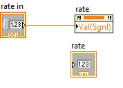
Hello
In "automatic mode" to change the sampling rate, the calculated rate is written in the local variable (as illustrated in the code). Structure of the event does not change value in the local variable as an event.
In order to make the structure of the event to recognize the change in value of an indicator such as event: write the new value to the property "Value (Sgnl)" corrosponding node to rate indicator (see figure below). This will make the structure of the event accept the value change in the indicator as event.
Note: Use architectures such as producers and consumers for such applications, which makes the application readable and expandable.
See rear queries if any.
-
I have a system with a map of the 9234 compactDAQ 4 Groove and a 9401 in slot 5.
I use a function generator to create a 5V square wave frequency sweep.
The frequency of scans from 1 Hz to 10 Hz in 3 seconds.
I have this tee in my door to counter 0 (PFI1 - 16 Pin) and an analog input channel 0.
In LabView, I do a period measure counter that has a trigger defined on the trigger to start ArmStart HAVE.
Piecemeal the signal into two channels, I see the time counter correspond to zero-level positive slope crossings in the data to HAVE it.
By the presence of a square with a mutation frequency wave, I know for sure that the time is not out of a period.
I noticed the downturn to take samples, the greatest moment of the synchronization error.
Here is the data that I have saved:
sampling rate 1 / (sync error times)
51200 1250
25600 625
10240 256
2048 51.8
1651 37
It worked of Y = 0,0244 X + 1.1262 with R ^ 2 = 1.0
So it could be, I have a programming error, or that there is a bug in the hardware or the base software.
Thanks for any help to understand this question.
BTW, I use this system to make an analysis program in the stopped vehicle with direct sequence over time - of course analysis based on the revolutions. I found that order analytical tools was not flexible enough for what I had done, so I started from the ground upward.
Hi Greg,.
Looks like you see the entry delay the NI 9234 (Group delay). As specified in the instructions for use NI 9234, entry delay is equal to 38.4 / fs + 3.2us. This is because of how the sigma delta ADC works - after the start, it must acquire a certain number of samples before returning the first valid sample. This delay is expected.
Here is a knowledge base on the subject. There are a lot more, just do a search of the knowledge base for "group delay.
-
Mode script for ANY c ++ function
Hi all
My goal was to use the pxi 5406 to implement features of frequency sweep. Right now, we use only the functions on the list of the frequencies of creation. There are four modes of release for the frequency list, signle, continuous, step by step and burst. We use the bleachers through fashion. It is painful to use this mode, since for each frequency, you need to send a rising edge, so if I have several hundred, it means I have to produce this amount of rising edges. This will generate a lot of buffer in another analog card.
My question is, could I use script for the frequency list view? Or is there a smart way to achieve this? From the file of signal aid, he said that there are some c programe on script mode. But I can't find any examples in my computer. If you have any other, could you send me?
Thank you very much.
.Yami.
Yami,
The 5406 has the ability to run script mode. Only for her output modes are Standard function and frequency list. However, I believe that you can do what you want to do with the list mode frequencies. Assuming that you do not want to trigger you can put the camera in single or continuous Mode. Single will play your select frequency scan and then once completed, build:
Continuous is similar, but you continue to repeat the signals to stop:
All the above details are in aid of signal generators of NOR. I looked under the heading devices > 5406 > trigger > triggering Modes.
With simple or continuous, you can specify the length of the waveform step, which could be a good starting point. With regard to the examples for c ++, I do not have, but if you look in the Start Menu, NOR-FGEN, National Instruments, examples, OR-FGEN C examples you can find a folder for "Sweep generator", there is a model and an example C you can look over your program after. I hope this helps!
-
Problem of Convergence HB in co-simulation EM-circuit
Hello
It would be really helpful if someone could take a look at the problem of simulation in the attached draft. I get errors from simulation - "step for source stepping size has declined under a permissible minimum value."and"poor convergence in the analysis of AC/DC (rel/abs err = 2,000 / 0.000) the biggest change (41) node in the node (46) maximum voltage = 53.076 minimum voltage in the node (MET_BASE!" _S12_LD1. R1.et) =-4.337 the biggest change in the branch (_S12_S1. I16) Maximum current in the industry (_S12_S1. I17) = 951,567 m current Minimum in the branch (MET_BASE! _S12_LD1.) R1. Bessel_L1. "(I) =-1735"
Despite trying most of the suggested solutions enumerated using the particular error message, the problem persists. What I do wrong here in the configuration of the simulation?
Thank you much in advance.
You check the use frequency of the project on block of EXTRACT properties > frequencies tab. So the structure of the MA is only simulated at frequencies of input: DC and not harmonics 5 simulation HB is taken into account. So microwave Office must extrapolate at these frequencies. Your block EXTRACT frequencies should be defined to include 0, 1, 2, 3, 4 and 5 times each frequency simulation... .to you chanage the number of harmonics in the harmonic balance options. You can also simply define the block EXTRACT sweep from 0 to 10 GHz. Whatever it is, the simulation of EM will take more time, of course. If AXIEM does not converge on a response, change the properties of block of EXTRACT > AXIEM tab, click the secondary Show button and under Advanced frequency sweeping (AFS), increase Max # sim points.
For circuits that include models not linear, you must include the frequency = 0 even for linear measurements, for the accurate calculation of the DC polarization.
-
Generate a signal FGEN 5421 and gettting on FScope 5122
Hello
(1) I need to generate a given signal
A [Sin (WT) + N * Sin (2Wt + pi)] by using PXI or 5421.I join the program that I created using Labview.The problem, I face by using this program, is that the maximum amplitude I can get is 1. Second thing, it is that I need to build only for some periods.
Later, I would like to make a sweep of this signal in the frequency range of 304kHz to 372kHz with a 0.5 kHz step size. How can I go about it?
(2) I'll send this entry signalinto my system and I am able to see the answer on the oscilloscope using the NI Scope front. I would like to know how I can use a labview program and acquire my answer with adequate sampling.
(3) I also need to convert the answer on my oscilloscope in a table of values so that I can import the table and generate the response in Matlab. How can I get the answer as a text file with a table of values?
Waiting for your response,
Thanks in advance,
David
I was wrong on my advise on the frequency sweep, kick these:
http://zone.NI.com/DevZone/CDA/EPD/p/ID/3327
-
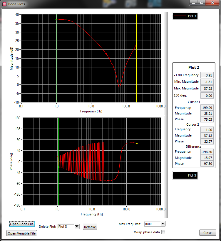
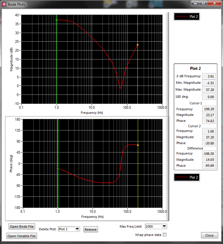
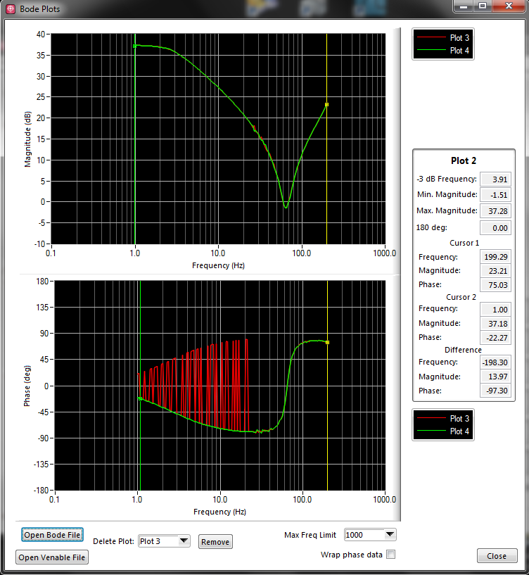
Bill land - problem with phase
I have a problem of implementation during the attempt to produce traces of Bode for my team designed the hardware. I have now successfully been able to produce the data you expect, with a single question. Part of the phase of data points are the opposite of what is expected. I'll explain the process used...
The material, I log in allows me to inject the signals on channels, but also the flow of these channels of my PC application for analysis. The function that I'm trying to replicate is a frequency sweep, as follows:
-major equipment to replace a channel (the stimulus) with an sine wave frequencies, f
-broadcasting the channel stimulus as well as his response to a certain channel number of cycles, P
-the analysis ("transfer function") on the stimulus and data stream response strings
-connect the frequency (f) with the phase intended to produce a Plot of Bode and corresponding calculated magnitude
-increase the frequency (f) and repeat steps
This code example is 'analysis' performed:
int i, MaxMagIdx, DontCareIdx;
Double * TimeInMag,.
* DontCareArr,
TransferReal,
TransferImg,
TransferMag,
TransferPhase,
DontCare,
AdjFreq;NIComplexNumber * TimeSweepIn,.
* TimeSweepOut,
* FFTSweepIn,
* FFTSweepOut;TimeSweepIn = malloc (gSweepCountMax * sizeof (NIComplexNumber));
TimeSweepOut = malloc (gSweepCountMax * sizeof (NIComplexNumber));
FFTSweepIn = malloc (gSweepCountMax * sizeof (NIComplexNumber));
FFTSweepOut = malloc (gSweepCountMax * sizeof (NIComplexNumber));TimeInMag = malloc (gSweepCountMax * sizeof (double));
DontCareArr = malloc (gSweepCountMax * sizeof (double));int InputSigIndex;
unsigned char OverrideMsg [L_ADC_OVERRIDE_RQ] is {0};.
for (i = 0; i<>
{
TimeSweepIn [i] .reellement = gSweepInArr [i];
TimeSweepOut [i] .reellement = gSweepOutArr [i];
TimeSweepIn [i] .imaginary = 0.0;
TimeSweepOut [i] .imaginary = 0.0;
}CxFFTEx (TimeSweepIn, gSweepCountMax, gSweepCountMax, NULL, FALSE, FFTSweepIn);
CxFFTEx (TimeSweepOut, gSweepCountMax, gSweepCountMax, NULL, FALSE, FFTSweepOut);for (i = 0; i<>
{
ToPolar (FFTSweepIn [i] .reellement, FFTSweepIn [i] .imaginary & TimeInMag [i], & DontCareArr [i]);
}MaxMin1D (TimeInMag, gSweepCountMax, & DontCare, & MaxMagIdx, & DontCare & DontCareIdx);
CxDiv (.reellement [MaxMagIdx] FFTSweepOut, FFTSweepOut [MaxMagIdx] .imaginary,
FFTSweepIn [MaxMagIdx] .reellement .imaginary FFTSweepIn [MaxMagIdx],
& TransferReal, & TransferImg);ToPolar (TransferReal, TransferImg, & TransferMag & TransferPhase);
TransferMag = 20 * log10 (TransferMag);
TransferPhase = RadToDeg (TransferPhase);AdjFreq = (double) ((unsigned long) (gSweepFreq * 0 x 200000000 / (double) 50000000)) * 0 200000000 50000000 x / (double);
fprintf (Logfile_Handle, "% lf\t%lf\t%lf\n", AdjFreq, TransferMag, TransferPhase);
Free (TimeSweepIn);
Free (TimeSweepOut);
Free (FFTSweepIn);
Free (FFTSweepOut);
Free (TimeInMag);
Free (DontCareArr);It works almost perfectly. The problem is that the calculated phase will be positive when there should be negative and vice versa.
Here's a graph of the data produced:
This is what is expected:
Here are the two bunk:
The expected plot was produced by the log file of cheating. I went and I didn't change the incorrect points to negative values. I want to eliminate this step. As you can see, if incorrect data are reflected on the zero line, it's what we expect. This "expected" given corresponds to what material Analyzer of my colleague (Venable device) when it is used on our device.
We believe that the issue is not with carried out complex math, but a problem in the FFT function or the selection of the index to use on the data table.
Hi PedroMunoz,
It was random semi.
With the help of a licensed physicist with a PhD, the solution was discovered.
When a FFT is performed, the output is a complex signal frequency. Convert this signal complex in amplitude and phase. The signal amplitude must contain a pic. The ridge of the signal amplitude is located at the frequency at which the sample represents. I understood.
However, reading the FFT also of output magntiude contains a second peak. This second peak is negative frequency, and to analyze these data point conjugate complex is necessary. This second Summit should theoretically have the same amplitude, described as:
F (f) = F * (-f)
What interests me in recovering is F (f). What was happening was because F (f) and F * (-f) are theoretically the same (hence, they should the two registry as the maximum value of the table), F * (-f) would sometimes be picked up as the maximum value of the table instead of F (f), perhaps because of the noise. So I just need to make sure that I'm not the negative frequencies in my table.
To ignore the F * (-f), all I had to do was only to watch a half of my output of the FFT. When I change my code for:
TimeInMag = malloc (gSweepCountMax/2 * sizeof (double));
DontCareArr = malloc (gSweepCountMax/2 * sizeof (double));for (i = 0; i
{
ToPolar (FFTSweepIn [i] .reellement, FFTSweepIn [i] .imaginary & TimeInMag [i], & DontCareArr [i]);
}
MaxMin1D (TimeInMag, gSweepCountMax/2, & DontCare, & MaxMagIdx, & DontCare, & DontCareIdx);I'm ignoring the negative frequencies. By setting the parameter 'shift' of CxFFTEx to FALSE, it organizes the positive frequencies in the first half, then the negative frequencies in the second. I pick up is no longer the wrong index, which would result in the phase reverse reading.
I hope this helps someone else in the future!
-
I'm developing an application to test the hardware components designed by my colleague.
My application can read signal from the material and data flows in a log file. In addition, I can order the supplies to perform a frequency sweep on one of its input signals. So I have the ability to connect to the input signal frequency sweep, but also a corresponding output signal.
I can then do two things with the file:
- Read the log file and read the signals on a strip chart. I have adjustable low-pass filters to reduce noise on the raw, if necessary.
- Read the logfile of a signal frequency-swept, to execute a transfer function on two selected signals and plot the data obtained on a size-v-freq and a graph of log phase-v-freq, aka Bode plots scale.
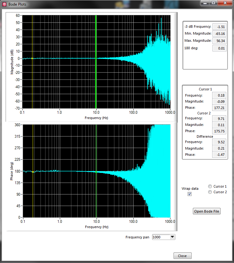
My problem is that my Bode plots are sometimes noisy, and I don't know how I should go about their cleaning.
Here is an example:
I know that the swept frequency input signal by was loud himself, so I thought to pass through a low pass filter before plotting, but it does not make changes.
I also saw all the options of the CVI curve adjustment, but I'm not competent in whether or not it would sense, especially for phase-v-freq graph, as its shape is indefinite.
Someone can push me in the right direction? I am sure there is information I provide not as well.
Hi Rachel,
For the example I provided, the input signal is "raw" unfiltered data. What it really is is forced to low sinusoidal voltage, which is summarized with the real signal on that channel on the material (which is the white noise of low voltage). For the purpose of our tests, we use the free entry and exit, and the output channel is simply the input channel put through a low pass filter. We see a (smoothed) sine wave phase shifted silent for output.
After a long discussion with my colleagues, we think we know where we went wrong with this example.
As I said, my application command equipment to do a frequency sweep. It is to reproduce what seemed the signals when my colleague uses his material (Venable) commercial frequency response Analyzer, which at the end of the day, we try replace by my application. How I got this set up has been the input signal would spend cycles N of a sine wave at the frequency f = Fstart, then f would increase percentage P cycles N to f = Fmax. N and P would remain constant.
We realized that if we kept constant N, us would collect enough data to higher frequencies, which is probably a lot of noise at higher frequencies due to the low SNR of the input signal. We believe that this could help clean up the ground, but we could still have a fundamental problem with how we have tried to make the TransferFunction.
I logged on to the whole of the file, would have extracted all input and output signals and performing the unique function of transfer on 2 tables of the data set. I think that we became aware that the error in this method is that while signals (in the time domain) seem to be reproducing the Venable, the Venable analyze each individual f step and produce a data point for the route of Bode. We now believe that this is how the CVI TransferFunction function must be used. That is, providing instead a signal complex (y = sin (f0) + sin (f1) + sin (f2) +... + sin (Fmax)). It would be too resource-heavy for our material.
If someone can confirm if it is the right way to use the TransferFunction, it would be very appreciated...
-
Hello
I have a model of generator Rigol DG5101 function and can not find the driver for labview. I found the driver for the 1 k and 4 k.
In the link: http://beyondmeasure.rigoltech.com/acton/attachment/1579/f-01be/1/-/-/-/-/file.vi
There is an example that does not work because there is no screws (: like rgdg5k, close.vi etc), is what I found.
I want to provide a driver such as 1 k and 4 k series if possible.
My interest is to make a frequency sweep as examples of the other series. I would also if someone can explain to me how to use the example called frequency sweep (attached to the series of discs 1 k and 4 k) with the DG5101 generator.
Concerning
-
Hello
I am looking for information on the extraction of a data file of the bascially solartron 1250 Analyser.The file is a scan frequency of 99 points. I am in communication with the Solartron via card NI GPIB/488.2.
I can communicate successfully between the Solartron and the GPIB using Labview and the default template of GPIB.vi in Labview.Also using VISA OR interactive control allows me to communicate successfully.
Communication via the GPIB.vi or the VISA allows me to read the first line/point of the data file created from the frequency of scanning on the Solartron.I can produce results of 1st line/tip of the frequency sweep in a txt file using the viReadtofile within interactive control of VISA. However I can't out all the points of the sweep in a txt only once file.
If I scroll to the next point/line on the solartron, I can read that point by using the GPIB.vi and with VISA Interactive Control, write that in a txt file.
However, as mentioned I can not all points of the sweep in a txt output file at the same time.
Should be changed to read all of the points on the solartron VI. Can this be achieved easily? Is there solution VI for the extraction of all the points of the solartron data file?
Thank you
Hello
It's old stuff was updated to version 8 so readable up to lv2010
Maybe you like it.
Maybe you are looking for
-
Firefox is compatible with a LG OPTIMUS?
Nothing seems to download.
-
Satellite L550 - 1 8: icons disappeared from the Office
Hello.Satellite my husband suddenly erased while he was using it. When the screen came back, all the "shortcuts" to programs had disappeared. The screen is white gray with the brand Toshiba passes through the middle of the screen. How do we get back
-
Equium A60 - 181: strange deformations on the cover
Hello. I have an old p4 A60-181 for 8 months with screen 15 3.06 inches.On the external plastic lid, I noticed a strange thing, starting to happen.Looking forward and down on the cover above the left side about 2 inches to the bottom and 2 inch from
-
MobileIron said: I am jail broken
I can access is no longer email work due MobileIron recital as a jailbroken phone. even after wipe and reformat.
-
Safari truncates the first letter of the email address.
Something new in Safari. When I type my e-mail address in a field he deletes the first letter of my e-mail address and I have to manually replace. Is this a problem with AutoCorrect? In the contact e-mail address has not changed.