Nor-daq-mx: generate multiple samples
Hello!
I need to send a binary file multiple to a multiplexer, when I get a TTL signal, then I need to read the signal for each sensor.
But my vi, just send 1 one after the other: /, I tried a lot of things, but I'm stuck.
Edit: FYI I use one or pci6251 and labview 8.5
Here is a simplified version of my VI and and draw little I did for you.
u didn't do well understand what I want to do but u can have another solution, in any case, I managed to succeed.
check the VI I attached, it works.
at each TTL, I generate a pulse train, and the binary words are synchronized on the pulse train.
Tags: NI Software
Similar Questions
-
Verification of task names valid in the basis of NOR-DAQ
Hello
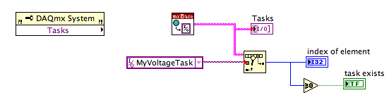
I have a question about the configuration of the tasks in the version of Base of NOR-DAQmx (I need basic because the application will need to be able to run on both Windows and Mac computers). The material is a box USB-6009, ordered through LabView. When you create a task inside LabView, is it possible to tell if the name you choose is already in use or not? Similarly, is it possible to get a list of and if all tasks are running?
The context is that I have a subroutine that made a brief burst of acquistion of analog input and then passes the result to the caller. I would like also to the subroutine to run standalone for different testing purposes. Normally, I would have the subroutine create and configure a task, the measure and then close the task. The problem is that the process of create/set up/start takes about 200-250 milliseconds (the measure itself is about 20 ms) that is long enough that I don't want to go through it whenever the subroutine is called from the top (I need to call this routine and do some other stuff a few times per second). So what I would is have the name of the task as a control on the subroutine, test that the value is a valid and if not valid only the initialization/etc. in the context of the subroutine, but if the subroutine has been passed a valid task from the top to skip a step all the time.
Looking through all of Base of NOR-DAQ functions, it doesn't seem to be something that allows me to do this kind of check with the exception of brute force to try to create a task and trapping so all errors that might be generated.
Suggestions (or ways) welcome.
Kelsey,
It seems that the property node is a component DAQmx, not a component DAQmx Base . I can't find any DAQmx Base property nodes.
dmsilev,
Try to replace the property node of the tasks with the DAQmx Base get tasks.vi. It is not in the DAQmx Base palette. It's a Subvi DAQmx Base create Task.vi. Caution: when you use a Subvi, which isn't on the pallets, know that they are generally not documented well and are subject to change in future versions of LV
If you weren't aware, DAQmx Base is written in LV and almost all the diagrams are not p [rotege so you can look inside and see how things are doing.
Lynn
-
How can I change the target directory for NOR-DAQ 6.9.3?
I try to install NOR-DAQ 6.9.3 on a new laptop computer. I tried to change the target directory, but the installer does not allow me to change it. Is it possible to change the directory?
When you say that the installation program does not let you change the directory target, you receive an error? In my view, is it possible to change the target directory by selecting the feature in the feature tree, then by manually changing the target directory to the bottom of the installer. When this is done, a pop up will occur who says a new folder will be created to save the files to.
-
MAX does not recognize NOR-DAQ traditional (old) devices * HELP
I have a card PCIe-6259. I want to use blocks of input-output in my program .vi (read Port DIO-DIO Port writing reading Digital Line), so I installed the version of NOR-DAQ traditional (old) devices 7.4.4. But when I got to MAX (measures & Automation) and look on the left side under devices and Interfaces, I do not see the Tradional-NOR-DAQ tab; I see only the devices NOR-DAQ-mx, PXI, series and parallel system.
Then when I go to run my program I get the error: error-10401 took place in a DIO Port Config Possible reason (s): NOR-DAQ LV: the specified device is not a product of National Instruments, the driver does not support the device (for example, the pilot exited until the device has been supported), or the device has not been configured using the Explorer Measurement & Automation.
So, how do MAX to recognize that I have installed NOR-DAQ traditional (old) 7.4.4?
Thanks for the reply! I realized this too after going through the files for example... but thanks for the confirmation.

-
CR1000 are accessible using NOR-DAQ?
Hello
I'm trying to control a CR1000 datalogger using Labview. Is it possible to configure the available CR1000 in NOR-DAQ?
Thank you!
Why do you think you can use drivers OR a product OR NOT?
NOR-DAQ is for products OR.
-
Problem setting Legacy DAQ board using NOR-DAQ 6.1 for Labview
I know that the Board of Directors is an old legacy product not supported by NEITHER, however for a low-budget project, I have 3 of these AT-MIO-16 x cards and the need to use them.
I know I got this job in the past not distant os, however, for the life of me can't get things sorted and work.
You use a NT box, in which this configuration used to work... uninstalled and started fees for other reasons, and I can not get the NOR-DAQ 6.1 to support LAbview 6.1 or 7.1.
Of course, I understand the OR-DAQ 6.1 should be used for Labview 5 and older, but also know this has been successfully done in the past.
I downloaded all knowledge base articles dozed or both support and remember to use successfully the last time that I set up so I know not somehow it works.
My configuration is: AT-MIO-16 X to the bus combo board (called work)
NT PC
LabVIEW 6.1 or 7.1
NOR-DAQ 6.1 is the most recent to support this card.
However, it will not install its support to its latest versions of Labview and I get errors, crashing, or missing files, when I followed various circumvention of knowledge base solutions.
I was hoping that someone has a documentation somewhere how to handle this, because it really is a matrix of spaghetti.
I can get NOR-DAQ support files installed, and Configuration Manager works well, finds the map and allows its parameters to be defined.
But when I load the DAQ vi of any type, Labview accidents and the wizard of data acquisition channel does not work at all (no error).
Thank you
Yes, the installation program from the folder of disks for NOR-DAQ 6.1 on the ftp site has worked well.
Workaround. Thank you
-
How can I generate multiple unique random numbers?
Hello
I am trying to generate multiple random numbers between a given set of numbers (1-52) and do not have the same number generated twice within this group. I can compare the numbers of last and next with the function to compare, but how would I go about comparison of all numbers generated without using a huge list of shift registers...
Any help/ideas are welcome and appreciated.
Jason
Solved my problem. IM passing the random number through a registry to offset to each case and build a table every time. I then searches the table for the new random number. If the number is not found I get a value of-1, another thing is an index value of 0-everything. If a comparator greater than (-1) indicates that the same number is in the table and then I can raise this matter until the same number is not found.
Kind regards
Jason
-
NOR-DAQ traditional vi not found in NOR-DAQmx
Hello. We hope to control a detector via NI PCI-6533 (DIO-32HS). Our colleagues have implemented control programs in BT 7.1 to 7.3 of NOR-DAQ traditional. Now when we opened their programs on a PC installed with LV 8.6 and NOR-DAQmx 8.9, many vi was not located, including "DIO config.vi", "DIO wait.vi", "DIO clear.vi", "DIO read.vi", "Reset.vi Device", etc. We realized that they were supposed to come from vi.lib\daq\digital.llb and a few other .llb in the same folder. Apparently vi.llb\daq was installed by the traditional DAQ.
We do not believe there is compatible with LV 8.6 traditional DAQ, which means that we need to replace those 'DIO *.vi' or 'Device reset.vi' with their counterparts DAQmx. Could someone shed some light on how we should start working on that?
Thank you very much.
Xiaolan,
Indeed, there is a traditional DAQ driver for LV 8.6. The installation can be found here. I hope this helps.
-
LiveCycle ES4. I am trying to move a picture online with a text box to create a header. I had to create a subform that flows to generate multiple pages of text. After changing the settings, it seems that I can't place the images and the text I would like. I tried moving them to the bottom, but does not work. Is there a way to encapsulate the images so that they can be places as much as I want?
Select your photo and text inside the subform flowed. Right-click and select wrap in subform do the positioned Subform subform. This will allow you to move objects in this subform positioned the way you like them.
-
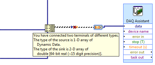
How to use generate multiple signals on a single DAQ Assistant
I am trying to generate several AO on my DAQ card, but I kept getting an error. I looked at the error and he said that I had to use a single DAQ Assistant. So, I created one, but I can't understand how to connect the signals. I get lines that don't connect. Is attached a picture of the installation. Thank you!!!
If you want to use the type of dynamic data, you must use the appropriate function. Do not use the construction. Use the Signal to merge. Then wire you the output of said directly to the Assistant.
-
Nor-Daq 6251 set hour/time between samples
I'm trying to calculate the expected error for an experience that I do and I don't know if I've done enough to determine the 'break-in' or the time between samples.
We use 8 differential channels to the maximum sampling frequency, the card can do (1.25. MECH / s). If I understand correctly, the minimum time between each sample must be 1 / 1.25 M, or 800 nanoseconds, such as the maximum time between sampling channel 1 and channel 16 would order 12uS (800nS * 15). If the expected voltage settings are the same for each channel (+/-10v), would a break-in? If so, how long?
In addition, if a channel is upward, and its tensions have an offset, DC on 5 or 6 volts, should that severely increase break-in if all other channels averaged about +/-1v?
I'm sorry for the basic question, I couldn't find a straight answer in the documentation.
Hi LSUgrad85,
When looking for specific device information detailed Specifications for this device will usually provide the details you are looking for. After the back if you have questions about the information in the detailed specifications.
I hope this helps!
Kind regards
-
Generate N samples with NI USB 6501?
Hi all
I would use my 6501 NI USB DAQ (simple DAQ with 24 DIO) in order to generate a 16 - bit model. Using the DAQ assistant, I'm allowed to select "1 sample (on request)", 'Samples N' or 'samples continues. " But, unless I choose the first option, I get an error stating that I can choose only "1 sample (on request).
What is a 6501 insurmountable limit?
Thank you
xdaf,
Found this statement in the docs for 6501. "All samples of the guidelines and updates lines are timed by the software.'". I would say that it will only work in mode "1 sample on request.
-
On a NOR-6363: how many digital samples can be acquired at once?
Hello
I use a NOR-6363 with meter 3 configured for pulse generation finished.
I created a digital input channel to acquire digital values (on P0.16 and P0.17) with counter3 as the sample clock.
The idea is to acquire a finite number of digital samples (even as the number of finished pulses generated on counter3).
Currently, I'm trying to figure out if I can get about 1000 samples (requirement of my request).
The data sheet indicates that the FIFO size for a digital input is 255. Is this to say that I can not acquire more than 255 samples at a time?
I tried to use high values up to 1000 but no error occurs.
Is this to say that the reading of values will be correct?
Or im guessing it might be a circular FIFO that overlooks the same values reading values of more than 255.
Should I worry about this limit of 255 at all?
Thank you
Since no one answered this yet and I posted my question there are times, I'll take a stab at a helping hand.
The FIFO on the digital input is the place on board where the samples will be kept until their transfer on the bus in the RAM. So, the question becomes what controls when these samples are pushed to the RAM. If I remember correctly, this card has 8 DMA 1 channel who will control when these samples are transferred on the bus. I don't think there is a way to control when the DMA channel completes his transfer, but the first transfer is likely before you fill up the first 255 samples. DMA transfers will continue to occur until all samples have been transferred to the PC RAM.
Once some or all samples have been transferred to the bus and reside on PC RAM, you call then call DAQmx read. Then, the samples are in your Application development environment (ADE) RAM, if you use them in your program. You have 3 separate storage locations: FIFO on board, PC memory, memory of the ADE.
You shouldn't have to worry about the limit of 255. Maybe if you were doing a very fast acquisition, this could be a factor...
Kind regards
Eric -
I am using a cDAQ with NI 9237 module and one NEITHER 9205 and LabVIEW 8.6.1. The two arecoded of modules using the DAQ Assistant in LabVIEW.
I would like to simultaneously read data guarantee of deformation (NI 9237) and data LVDT (NOR 9205) in order to operate a piece of equipment from laboratory to different load profiles. However, when I try to run the VI with two Assistants DAQ continuous sampling value, I get an error saying that the 'resources are not available."
To work around this problem, I tried to have both alternate between taking a series of samples. This method is insufficient, as it produces choppy data that controls a machine cannot be invoked.
Sorry if the words I have used are not good. I'm kinda new to labVIEW.
Thank you
I assume you are using cDAQ-9172 chassis.
This was just an analog input synchronization engine, which means that only HAVE task can run at a time.
-
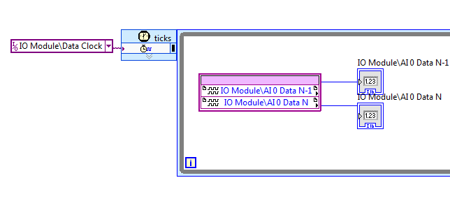
Module e/s NI 5761 clock compiled 0 to 100 MHz in single/multiple Sample CLIP examples of projects
Hello
I was trying to wrap my head around the CLIP sample NI 5761 Multi (v4.1.0) because the CLIP provides 250 PSM data, but the IO module requires a clock of 200 MHz. I think, ' NOR should handle the conversion of the clock, fine, but I hope that the diagram is running at 125 MHz... otherwise I'm really confused "so I look at configuring the clock Module e/s in
0 \examples\FlexRIO\IO Modules\NI 5761\NI Getting Started\NI 5761 5761 - to Started.lvproj and to my surprise, it is compiled for 100 MHz. I checked the target 7965 in NI 5761 single sample CLIP\NI 5761 - unique CLIP.lvproj and IO Module clock 0 sample was compiled for 100 MHz there as well.
I do not understand the difference between the flow of data and the selection of clock 200 MHz IO module, and it would be nice to understand it, but not necessary. Also, I don't understand the difference between data rate and the configuration of the Module e/s 0 clock that drives the SCTL that contains the node IO. I understand that to move forward.
Thanks for any help,
Steve K
The CLK200 in the selections of the clock is used to excite the parts of the fixed logic that are internal to the CLIP. Some CLIPs FlexRIO may only require a CLK40, this one requires a CLK40 and fixed a CLK200 to properly perform its logic. Thus, it seems that everything is ok in regards to that.
Unfortunately, the example incorrectly uses IOModClock0. The SCTL AI IO node resides in should use a resource of the clock that says "Data Clock. We've updated the examples in more recent versions of the pilot, but you seem to be using a version of the driver where a CLIP that uses the clock of data is the latest available for the 5761 CLIP, but the example has not yet been udpated to use.
Maybe you are looking for
-
15/05/2014: I lost my bookmark manager
HelloWith the last update, on Windows Vista, I now no longer have a bookmarks manager or a historical window, what Miss me. Is there a way I can get these things back? I added a new folder of bookmarks in the "Add bookmark" dialog box, and I can not
-
IPAQ 112 - everything software or drivers always available?
Hi all Need a little help pease, if someone can share a link updates to software or drivers or rom? HP ipaq classic Pocket Marvell pxa310 processor Proc Rev A1 Language of the WWE ROM date 18/10/2007 Review of the ROM v1.00.01 OS Version 5.2 The size
-
After installation that does not display the icon clipmarks, installed twice
Sometimes, back my icon disappeared, uninstalled and reinstalled clipmarks, twice, but still an icon will not appear. Impossible to use. This has happened Each time Firefox opened == Did not notice until about a month ago
-
Problems with "BLUE SCREEN" on Satellite A300D-205
Please help me find a solution for my laptop. When editing Windows 7 Ultimate 64 bit he works 2 or 3 days then appear the ugly 'blue screen '. I instaled Windows several times but every time that he do this 2hit.When I instaled to time windows 7 firs
-
I have Visual Studio 2010 Professional. On the start page, I started with file, new Web Site and you click New ASP.NET Web Site. I created a new web site and added a default.aspx page. I want to create a library of classes (entity component) and then