OCXO-SMU-6674 t PXI_CLK10_In questions
Hello
Currently I have a SMU-1082, SMU-8101 controller chassis and an SMU-6674 t timing card installed in slot 4. What I want to do is connect the oscillator on the timing card to clk10_in to improve the accuracy of the 10 MHz reference clock.
So, here's the strange thing, mostly when I run my labview program he fails to connect saying "PXI_Clk10_In is available as a terminal only for devices in a synchronization of the destination system slot. Place your unit in a timing system slot. "and will give you the code of error-1074118597. When it breaks down I try to run the code sample to connect to PXI_Clk10_In and using MAX and it will give me the same error, but from time to time, it will work without a single error.
Whenever I turn on the frame the first thing we do is check to see if I can connect the clock, and if I can it give no problem, but if I can't do it seems that nothing I will fix it and it will remain for a period extending over several weeks to a few months. When it works, the longest, it lasted a week.
I was wondering if someone runs into something like this before, or has any suggestions on how to make it work on a regular basis?
Also if I connect to PXI_Clk10_In or not, I am able to divide the DDS and it output ClkOut so it isn't a complete failure of the module comes from the ability to connect to Clk10_In.
Just to be sure, you can try to install the patch OR-Sync 3.4.1. This hotfix provides a picture of firmware updated for the SMU-6674 t. For more information on the fix, click the link below:
Module synchronization SMU-6674 t unexpected behavior
Kind regards
-Tyler
Tags: NI Hardware
Similar Questions
-
88302 error when you run the SMU 6674 t
Hello
I had two chassis SMU 1085, that each of them has a 6674 t module installed in the housing of timing.
Timing modules appear in the MAX, but
I get the 88302 internal error has occurred message when I try to do self - test, run the test Panel.
The synchronization OR installed version is 3.3.5 what I belieave is the largest leatest.
Any suggestions on how to help me solve this problem and get my operational module would be wellcome.
Thank you
Maciej
Maciej salvation,
The NO-Sync 3.4.1 version became operational today. Since NEITHER-Sync 3.3.5 we fixed some issues that may affect the SMU-6674 t driver initialization. You could try to install NO-Sync 3.4.1.
Kind regards
-Tyler
-
Question about 6674 t FlexRIO 7966R and Module AT - 1120 FAM DSTARA
Hello
I have a chassis SMU-1085 and following committees installed:
Slot 10: Module of synchronization for the SMU-6674 t
Slot 02: SMU-7966R FPGA
Attached to the SMU-7966R FPGA is a module of adaptation AT1120.
I'm trying to provide a clock of 125 MHz by the 6674 t the bottom of basket DDS output to power the clock DSTARA the SMU-7966R and then the module adaptation AT1120 as the clock of the DAC.
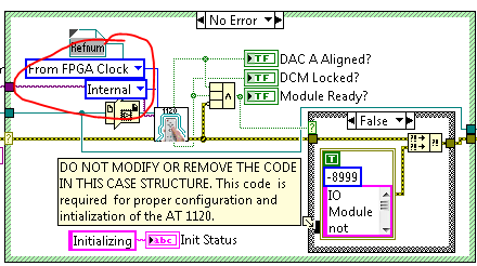
I'm currently using a modified version of the AT-1120 Getting Started project (https://decibel.ni.com/content/docs/DOC-26331) and have the Adapter Module set to take an internal clock and from FPGA clock as specified in the AT-1120 user manual:
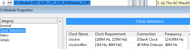
For my adapter module CLIP on the FPGA VI I have the clockin set to the DStarA Clock as shown below:
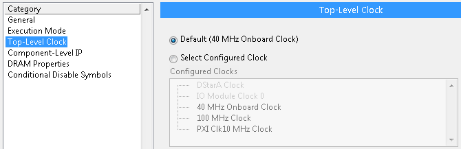
For my FlexRIO 7966R I have the toplevel clock set to the defautl 40 MHz onboard clock. I cannot use an external clock for this:
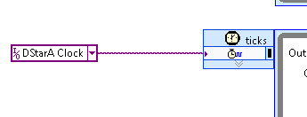
Then I have my SCTL clock set to the DStarA Clock:
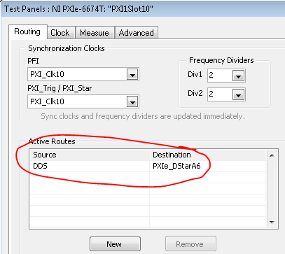
For simplicty sake, I am trying to feed the DSTARA clock using the test panel in NI Max with 6674T as follows. Becuase my FPGA is in slot 2 on the 1085 Chassis, I am feeding the 125 MHz DDS frequency to PXIe_DStarA6 based on the PXIe-1085 user manuel (http://www.ni.com/pdf/manuals/373712e.pdf) specified timing DStar lines:
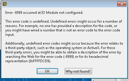
However, when I try and run my VI with all of these settings I get the following error:
Has anyone seen this, or can anyone advise regarding this? Maybe I'm using the DStarA lines wrong or something, but I'm not sure. Any help or suggestions from the community would be great!
Thanks for all your help!
-GMac
GMac,
Hello!
There are three things that I think that in the combination will solve this problem.
1.) can not included it in your screenshots, but there is an extra step you need to do to use the DSTAR. The bitfile you are using must be respected with a parameter that indicates the FlexRIO use the signal DSTARA.
- Right click on the Module adaptation of your project and select Properties
- Go to the category details
- Make sure that "PXIe_DStarA" is selected in the section "IoModSyncClock".
- If it is checked, then you have probably already chosen it and compiled your bitfile. If it is not selected, or you are not sure if you have compiled the adjustment, re - compile your Bitfile.
2.) also, what you see was a known problem that has been fixed in Active Techonologies (AT) last software update (version 1.8). While I'm not 100% certain, I don't think the example started to get has been updated so that it includes all the screws of the ATs software update. Similarly, the bitfiles provided with this sample would have not generated with the CLIP included in the latest version of the software.
I suggest the following:
- Download the latest version of the software (version 1.8) AT their site
- Use the example that comes with their software to confirm that you can clock at DSTARA
- Update of our example started to use the latest version of the software. (generate new bitfies, replace the old screw in the directory of the project with new screws)
- Confirm your new works for example.
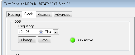
3.) generate a signal from 125 MHz of the 6674 t, not 124,98 MHz. The material is expected a 125 MHz signal. Dialog said 124,98 MHz with workaround for an odd present which was causing compilation failures. If you would like more information about this, let me know and I'll fill it in you read this post on the forum: http://forums.ni.com/t5/LabVIEW/7966R-DSTARA-Clock-and-AT-1120/m-p/2932916#M847692
I hope this helps!
-
Impossible to compile of the SMU-8101 Code
Hello
My system is an SMU-1065 chassis (I also had the same problem in the SMU-1082 chassis), SMU-8101 controller with Windows 7 installed by OR and the following instruments:
DMM PXI-4071, power supply PXI-4110, DAQ SMU-6356, calendar card SMU-6674 t and Motion Control PXI-7332.
I also have a SMU-8361 which I use from time to time and will be what I use in the long term.
Now for the real problem. What happens is I put all code in labview by using the instrument of VI driver and everything works perfectly. I can do VI calling Subvi appeal VI instrument and it works fine, but if I double click on a VI instruments and then try to watch the block schema, for example, opening 'DAQmx create channel (I-voltage-Basic) .vi' it seems to break the code. At first he said nothing but once I hit the button the arrow will change to the broken gray arrow and claim that the code could not compile (this is without actually changing anything with VI, I open it and look what he did).
Also any code I wrote called VI now get the same error if I click display error it will bring up a window I was looking for, so if I was watching the façade, then clicked on see the error it would bring just to the top of the front again without bringing out something. If I create a new file and build a little vi using instrument drivers, it works very well, if I copy the vi of the broken code and paste it into the new file it will fail with the same error.
It is not to have this behavior with all the instrument of VI, but will happen with some. I mentioned, it comes up with 'DAQmx create channel (I-voltage-Basic) .vi' but then this does not happen with "DAQmx Timing(Sample_Clock).vi. I have not experienced and verified exactly what VI he comes up with, but it seems to happen with other drivers of instruments as well, not only for the acquisition of data. It seems also that occur when you use the SMU-8101. If I connect it to a computer this is not pop up. My business control primarily the chassis using MXI cards so we have no embedded controllers available that I could swap in to see if it still happens.
It's not a big problem, glancing in the instrument vi is not necessary for me to do my job, I just do it to try to better understand what exactly is happening, but it's something I'm curious about.
Hi arielm,.
Have you tried to repair or uninstall/reinstall DAQmx? You can find the latest version here: http://www.ni.com/download/ni-daqmx-9.9/4707/en/
-
Problem of generation of Sync trigger in several synchronization USRP RIO 2943R problem
Generation problem shutter Sync in several synchronization USRP RIO 2943R problem.
Previous SR you may already know I'm stacked in USRP RIO multiple synchronization problem, especially in the mode based on the signal. Now I can cut down, the problem is mainly due to the outbreak of sync signals generation.
First of all, I read the article and the discussion in the following two links:
http://forums.NI.com/T5/USRP-software-radio/how-to-synchronize-multiple-USRP-Rio-294x-devices/TD-p/3...
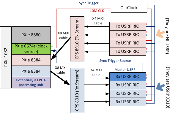
http://zone.NI.com/reference/en-XX/help/373380D-01/usrphelp/synchronization/and I did my connection of the material according to the suggestions in the second link. My system schematic is shown in the following image:
I checked OctColck and SMU 6674 T connections. They are all connected correctly and the cable are fine. I use the niUsrpRio200_XcvrSyncPps.lvbitx.
According to the description of documents and discussion forum, the USRP RIO 1st in the list of devices are considered to be the USRP Master. Then, the FPGA to master USRP RIO released "trigger of sync" signal through the 'PPS Trigger Out' SMA port in RIO USRP box.
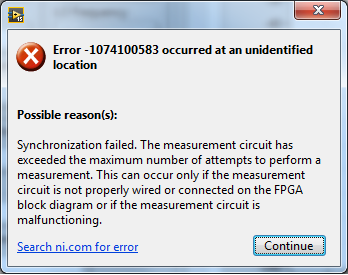
Based on the my analysis of the system, the first impression I have is the USRP Master does not export the 'sync trigger' correctly. The host VI reports the error like this:I was trying to measure the "synchronization trigger" using oscilloscope, but I found that it is impossible, because the host VI can not yet run, so there is that no signal can be seen from port 'PPS Trigger OUT.
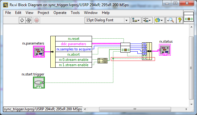
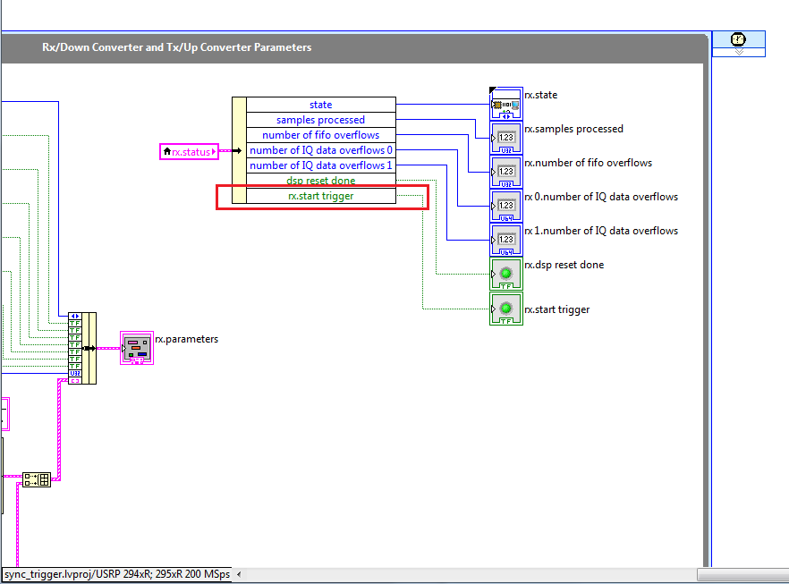
So I think that if I can watch this signal "sync trigger" in home VI by importing this signal from FPGA to host VI. I did some changes on the FPGA VI as shown in the following image to watch this signal of façade of the host VI. but not so successful. the rx.start tragger relaxation and tx.start do not appear on the host vi read/write control function.
-
Example of clock routing 'Terminal of Destination' = 'BoardClk? '
Several clock routing examples have a Terminal of Destination of "BoardClk". I can't find any documentation on what this is or where he's going. I've attached an example, "Route Clock.vi", which can also be found in example Finder > material input and output > timing and synchronization > Signal-based > road Clock.vi.
Specific material, with what I experience is the SMU-6674 t. I looked in the manuals for the SMU-6674 t and the SMU-1082 chassis. Google has no results.
Hello
Examples of NO-Sync include a number of modules. As a result, some of the terminals listed in the examples are not available on the SMU-6674 t.
BoardClk is only a valid terminal on the PXI-668 x modules. This terminal is used internally by the multi-device PXI_Clk10 software disciplining. With the PXI-6683 (H), this terminal can be used for single-device PXI_Clk10 discipline as well.
Kind regards
-Tyler -
Using SMU 6612 to measure PXI-6528 pulsewidth channel - channel is not available.
Hi all
I use SMU 6612 card counter to measure the pulse width of the signals to PXI 6528 DIO card. These two cards are in the same chassis PXI (NI-SMU-1065). I could measure the pulse widths using the example LabVIEW 2013 Counter - pulse width of reading and (over) frequency example of .vi. However not all channels of the PXI-6528 map appear in the drop-down list of channels on the pulse width can be measured. Try to connect any other channel that those which are available in the drop-down list returns the error. On the PXI card port 6528 0,1 and 2 are entered ports and port 3-5 are output ports. I can measure the pulse on port 0, 3 width and line 0 port 1 and 4.
Can someone explain to me why don't see port 1 or port 2 channels in the drop-down list or force the VI to measure the width of pulse on these channels?
I can plug PXI-6528 external input channels SMU 6612 counter input channels and measure the pulse width, but if possible I'd like to avoid the external wiring between the 2 cards.
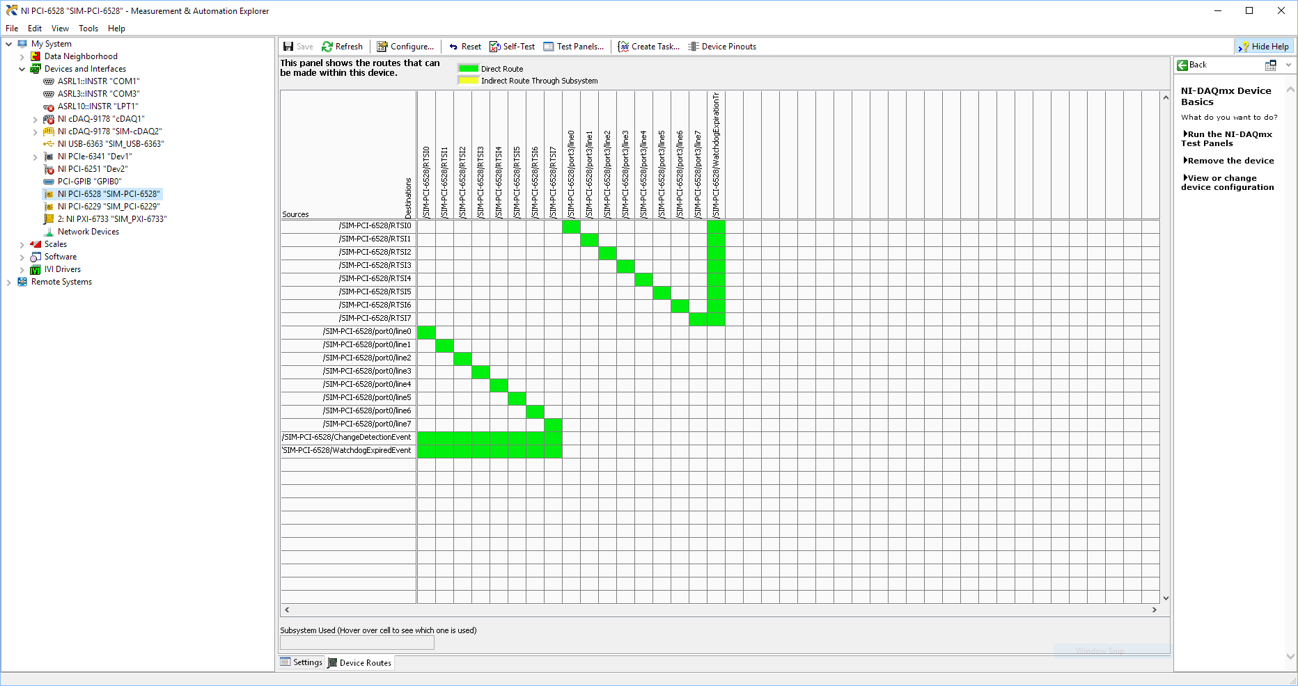
Probably not. Unless the routing plan is in fact reversed as it seems a bit sorta that. As stated on my system, you can route * of * a port of entry * to * RTSI, or you can route * of * RTSI * to * one output port. This does not make much sense to me, but that's what I see:
If the routing card * is * reversed, your only likely workaround without physical wire would be to generate impulses in question of port 3. It's pretty clear that 1,2,4,5-tetrachlorobenzene ports have no ability to interact with the bus timing, physical wiring would be the only option.
-Kevin P
-
I use the SMU 4140 to measure the curves of voltage/current for the transistors - it sets a voltage & I read (not necessarily on the same channel). But I noticed a peculiarity in the data according to the current limit.
First of all, I get different results if I let him autorange device compared to manually set the current limit.
In particular, there is a current lag that occurs for differnent current limits.
In the attached file, the current is allowed to Auto for the Red data and fixed at 100 Ma for data in blue. [the axes are current drain source - ID- & door - Source voltage VGS]
Any idea what is the origin of the offset .02mA in the Red data?
Thank you for following up with an explanation.
Looks like this resource to answer your question:
http://digital.NI.com/public.nsf/allkb/EE869FC813944EAC862578F0005519F5
-
Band bandwidth SMU for FPGA chassis
I'm specing on material for an FPGA FlexRIO system. The module FPGA and adapter, we will use has already been defined, a 7975R and a 5782. For our application, we will be streaming 2 inputs analog on a RT controller attached. From my understanding, these samples will be single precision floating point numbers, each of which is a piece of 4 bytes. Assuming that the 5782 max sampling rate is used, 250 MECH. / s, I think that I will need 2 GB/s of bandwidth on my SMU chassis.
Here my question, then, what SMU chassis should I consider? The SMU-1082 has "up to 2 GB/s per-slot dedicated bandwidth", but it is a real or theoretical number? Normally, I would just get the next thing that high, just to be sure, but there is a significant price difference on the way to the SMU 1085, which is also much larger I need. So I would like to save space and several thousands of dollars if I could get away with a 1082. Sampling does not quite to the max modules of adaptation would be acceptable, but I would be interested to know where about my maximum sampling speed would be.
Thanks in advance for your help.
The 1082 has more than enough bandwidth to stream data at a time to the analog inputs of a 5782. The 5782 has a 14 bit ADC with two channels that sample to 250 ms/s. These samples are returned as an I16 with the two least significant bits filled with zeros.
So assuming that you transfer all I16, rather than packing the 14 bits of data, you would have the following bandwidth requirements.
2 channels x 2 bytes/sample x 250 mega-samples per second = 1 GB/s
The 1082 a 2 GB/s of throughput dedicated per slot. The 7975 accommodates up to 1.6 Gbps streaming. I would recommend calling chat with someone, if you are looking for a recommendation on what type of chassis to purchase, but based on the requirements of streaming that you're fine with the combo 7975 and 1082, you thought. Just make sure you get a controller which can accommodate streaming speeds you're looking for. The 8840 is a good candidate.
-
Hi all
I moved this question here because it is a more appropriate Board.
I'm looking for measurements of current weak on my HAD and therefore seeks to including the guard on my DUT PCB assessment cables. I have two related questions on this issue.
1: the pinout of my SMU-4141 said that there are two pins on guard and I verified this with a DMM, they are linked and lead to the same level as the channel HI. However the cable recommended DB25F-DB25F low leakage cable only has one of these pins connected through guard. Is this correct or is there an error with my cable? I checked all 4 channels and they are all the same.
2: anyone know of any good information / best practices for custody of follow-up on my circuit board?
Thank you all,
Nick
Hi Nick,
Yes thank you, very good, moved to AE a year ago to SRI.
In order to have a reflection and a look at the wiring diagram (which I'm sorry to say that I can't send you in its entirety) and I think I can help with the confusion.
The cable we're actually talking about is not composed of coaxial cables, it is composed of twisted with son of drain and a pair conductive sheath. The son of drain are inert and not get connected to anything, so, leaving twisted pair and their sheaths. There are 8 twisted pairs and gaines in the bundle that gets wired on this connector, which means that 24 potential connections, with pin 13 no wired what whether that make up the number to 25.
Now bear with me I'm sure it's logical: twisted pair number is wired to the pins 2 and 14, which are the two pins of HI for channel 0 in and out. The shield for this twisted pair is then connected to pin 1 (a guard PIN). While guard pin protects both the two pins of HI.
Twisted pair two is connected as well: one half of the twisted pair is connected to pin 3 (LO sense), the other half is not connected and the shield is connected to pin 16. Now if I understand correctly, the son LO need not so much caretaking, so the extra yarn I guess looks more like a thread of drain here.
The schema for the cabling continues like this. Half twisted pair are the SIH strength and direction for a channel that is guarded by a shield wired to an agent, and the other half are wired with LOs and an additional drain.
I don't know why we didn't use COAX when help files, explains using the COAXIAL cable, but I suspect is has something to do with the cost (one of the AEs who graduated from the electrical eng said COAXIAL is much more expensive than the sons of the twisted pair, but he said also it is much more difficult to disassemble to weld so I suppose it would make many of these cable manufacturing) very expensive and difficult).
Now with regard to PCB stuff, I'll be honest, it's not some thing that we have a lot of documentation OR on, but of what google tells me, guard lines can be incorporated in a KIC and from what we have seen in the cable, it looks like we want to keep the HFD for both strength and sense. I myself am a physical grad for PCB design is not something that I've had too much experience with.
What is the next CSLUG meeting (also like the mascot of the group, sea slugs are beautiful!)? I introduce the CLD Summit in early September at the Newbury office if you go to that?
Thank you
Viv
-
I have a chassis 1075 SMU SMU-8133 controller and SMU-5186 digitizer and HDD-8265 RAID connected via 8262 PCIe link.
Basically, I need to broadcast the digitizer on the RAID output.
In LabVIEW, we can use NEITHER-SCOPE to acquire the data of digitizer and just write on the disc. RAID is configured to look like a normal drive to LabVIEW, the only difference being a higher write speed. The problem with this is that the data came by the controller. In my understanding, there must be a way to get the sample output scanner directly to the RAID, to avoid loading the processor, which is a potential bottleneck.
Any advice on how to do it?
P.S. I also counsel SMU - 7966R Virtex5 FPGA in my system, it would be interesting to route samples to RAID via FPGA card and do some signal processing everything in it. Is this possible?
Hello
I was looking into your question and found a few links that may be useful:
-This article talks about a controller of Direct-to-disk that would allow data to be streamed directly from the memory of the device on board your instrument and through the PCI/PCIe bus, as well as a few other infromation device memory considerations and architecture streaming: http://www.ni.com/white-paper/3221/en/
-Here is another useful article that addresses different configurations of RAID that you can use as well as points of reference for the various drivers: http://www.ni.com/white-paper/5897/en/
-In my research, I also found this post on the forum that is somewhat related to your question. It seeks to use peer to peer streaming to transfer data from a 7966R SMU to a NOR-8265, although this RAID is not Peer to Peer support: http://forums.ni.com/t5/LabVIEW/peer-to-peer-streaming/td-p/1935839
Thank you!
-
I have a pretty basic question for the SMU - 2527 32-channel, 300 V switching and multiplexing. In the documentation it says this multiplexer can be configured as a 1-wire double 32 x 1 Multiplexer. This means that the two multiplexers 32 x 1 are completely independent between them (which means that I can control separately and establish different connections)? Also, for my purposes, I intend to have a 32 x 1 multiplexers route 24VDC to 32 test points, and the other 32 x 1 Multiplexer will route 32 test points to a signal conditioner. For the 24VDC multiplexer, I need router the 24VDC to multiple test points at the same time. With this module it is possible to make multiple connections with a single multiplexer, or are you limited to a single connection of output at a time? Thanks for the help.
Hello
That's right, working in means of 1 double wire, 32 x 1 topology you can independently control each multiplexer. I would suggest the use of panel test this card in up there you can select the topology and to check that you can control each of them separately.
As for your second question, you can connect several channels to COM working in independent topology.
Kind regards
MCOTO
-
Type of step IVI supports NI-SMU-4112?
Hello, guys
I have a SMU-4112 and four of the PXI-4130. When I try to configure my SMU-4112 with PowerSupply IVI step Type, an error occurred.
-------------------------------
An error occurred the call "RunStep" in "ISubstep" of "ZNIUGOL of Types of step TestStand Ivi"
An error occurred during the execution of the step.
Component works IVI control error: IVI configure failed for logical name ' 4112 ".
Details: Attribute or property not supported. Attribute: NIDCPOWER_ATTR_OVP_ENABLED, Channel: 0 [IVI. Error Code: BFFA0012]
Source: TSIviStepTypes--------------------------------
Surely, I disabled the checkbox "OVP on" editing it IVI Power Supply stage dialogue. My system configuration is,
IVI Compliance Package 4.6
NOR-DCPower 1.8.6
SP1 OR TestStand 2012
My PXI - 4130 s work well with the type of step of IVI. Type of step IVI supports NI-SMU-4112? Or I do something wrong about this?
Kind regards
Joonam
Hi Joonam,
PowerSupply IVI step does not currently work with the 4112.
The 4112 can't stand the ÖVP. If the NIDCPOWER_ATTR_OVP_ENABLED attribute is set to True, the error you described is expected. If it is set to False, no error should be generated. However, an error is generated when it is set to false. This is incorrect behavior in the pilot and has already been documented under the Corrective Action report (CAR) #437105. This question will probably be corrected in a future version of NOR-DCPower.
Step PowerSupply IVI is hardcoded in the attribute set to true or false, depending on the value of the checkbox in the tab limits. Workaround for this problem is to replace your PowerSupply IVI step with a step based on a code module that does not seek to set the OVP_ENABLED attribute at all.
I apologize for any inconvenience that this is for you. Let me know if you want more details.
-
Channel of the DAQ (SMU-4498) task order
I have an SMU-4498 for which I generate an acquisiiton task programmatically. When the task is created channel order is not necessarily in ascending order of channel number.
My question is if the DAQ card will return the data in the order in which I defined the task or channel order?
Thank you
It seems that the answer is that channels must be specified in the order, when creating a task.
-
Acquire more than 2047 samples with the PXI-4461 instaled in SMU-1073
Hi all, I would ask you for help with the buffer limit.
I intend to buy digitizer PXI-4461 and he instal in SMU-1073 chassis, namely control via MXI Express of Labview installed on a separate computer.
What I need:
-to acquire data of a single channel of AI, but at least a sequence of 20 kS by a acquire task, in some situations until 200kS by a task to acquire.
The question:
- I can gain more than 2047 samples in a single sequence, like 200kS, with the PXI-4461 installed in SMU-1073?
Internal buffer of the PXI-4461 is reserved to 2047 samples. So I'm not sure if Labview can download remotely via MXI Express the data in the buffer of the PXI-4461 via MXI Express fast enough without any affection of the sampling program.
-in the case, this PXI-4461 with SMU-1073 isn't the right combination, what chassis and a controller can do?
Thanks much for the reply
Jan
It will work for you.
The on-board buffer 2047-sample is used only as a backup if the flow of data to the PC host (via MXI Express in this case) is not fast enough... that it will be (explained below). DAQmx transfers data from the buffer of the device to the host PC as fast as he can and, in ideal conditions, should not save the buffer 2047 much at all.
Let's just say you get 110 MB/s (randomly from a MXI data sheet) flow on your MXI connection. The 4461 has 2 analog inputs, which will be at 24 bits, we just round 32-bit in case it transfers the data in this way.
4 bytes/sample (32 bit) x 200,000 s/s x 2 (channels) = 1.6 MB/s, which is well below the 110 MB/s, which will make the MXI link.
clear as mud?
Germano-
Maybe you are looking for
-
Qosmio X 300-11 - impossible to get 1080 p @ 60 Hz to work
I have a Qosmio X 300 - 11s and little matter how hard I try, I can't do 1080 p at 60 hz. In fact the time is not yet available. I choose only 24 p or 30 p on my Full-HD is displayed even if they take over 50 / 60 Hz.I have the latest drivers install
-
Transfer files of Microsft money 7-Microsoft Money Plus Sunset Deluxe
I use Microsoft Money 7 on a laptop very old (more than 8 years) using Windows XP and I recently got a newer, faster laptop using Windows 7 I just install Microsoft Money Plus Sunset Deluxe on. My question is how can I move all my files in Money 7 to
-
I deleted somehow Accessories/System Tools (i.e., defrag, etc.) my program files folder. I tried to locate this program in the Windows Download Center, but was unable to do so. Where and how to find what program to download? I am running XP with SP
-
Could not get turbo tax 2010 to launch after be installed. I have a windows XP Home Edition.
Any chance of a solution to the problem of Megan558? I have exactly the same problem. I installed disc and download from the Intuit Web site. Also tried a clean boot start and still no luck, no new error message. I'm on the extension until 10/17/1
-
Each time use my games (solitaire ect) the Pentecost restars pc Coman did not, if I live the pc it will refute every time