Of signal generator HP8642A
Hi all
I want to control the generator of signals labview HP8642A but I could not find the driver for this model of NOR. This model was obsolete since 2007. Does anyone know any driver that supports this model?
Thank you!
NNA
You can see how much time LarsUrich got: http://forums.ni.com/t5/LabVIEW/Button-Operation/td-p/1612514
Tags: NI Software
Similar Questions
-
With the help of the external RF signal generator
Hello.
I just want to ask how can I remove the frequency shift if I use an external RF signal generator (instead of the RF PXI-5652 signal generator module). I understand that in the case using the OR to generate RF signals, frequency shift is deleted by setting the same source of reference for the transmitter and the receiver clock (placing the clock source of reference to PXI_CLK of the façade of generation VI and VI of the acquisition).
Thank you very much.
Hi Betty,.
In this case, no changes are needed, such as modules OR still use background clock basket PXI as the ref. clock source If you are still having a frequency shift, you probably need to configure sig gen to lock a clock external REF. Usually, just make the connection of the signal is not enough - you must also indicate the sig gen to use the signal connected to the input clock ref. Terminal
If you use the sig gen as clock source master Réf, connecting the 10 MHz of the gen of GIS at the BNC 10 MHz IN on the back of the PXI chassis replaces the clock native from the newly connected with the PXI chassis backplane, and analyzers are still using the clock background basket PXI as the source clock Ref (no change to the SW settings).
Kind regards
Andy Hinde
RF systems engineer
National Instruments
-
Output a TTL HIGH 10 usec via the PFI port on AWG signal generator
LV dear community,
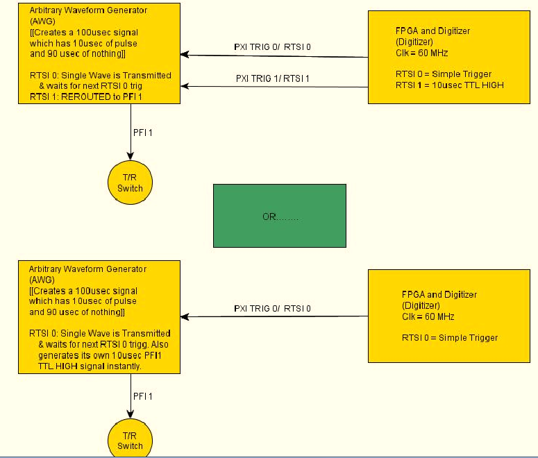
I want my signal generator (PXI-5422) to produce a pulse of 10usec with its PFI1 range each time that a wave of exit CH0. The frequency of repetition of the CH0 impulses and the port of PFI1 is 10 kHz. Is it possible for the signal generator automatically generate this HIGH TTL signals for usec 10 on the PFI1 line all at the same time produce a long-wave 100 usec?
Another approach, that I'm considering is to re - route a pulse of RTSI1 (10usec) from an FPGA and output via port PFF1 of the GTS. However, I doubt that this is possible, as the HELP MENU for the working group said that the report can only occur when the Working Group is in "idle" mode.
Any help will be greatly appreciated!
Have a nice day
 I have attached a diagram of operation that hopefully, explains what I'm trying to do a little better. Once again thanks for looking!
-Daniel
Hi Denn_Mann,
To get around the limit of 320ns, you should be able to use scripts with the FGEN markers to achieve your goal. Anything you want to do is use of script with markers in alternating mode. You may want to toggle high then low rocker after the number of samples you want pulse is high while your signal is present. I've linked some information below that should be good resources for script for you if you are not familiar.
Trigger on the arbitrary signal generators and advanced waveform sequencing
Creating an event marker in Script Mode
Script mode
Example of the expedition: "Fgen Arb Script.vi.
Kind regards
Ann Travis
-
calibration of Agilent N5183 Signal generator for specific output level
Hello
Newbie to labview environment! I'm writing a VI to calibrate Agilent N5183 to a specific output. For example if I want to have-4.5 dBm output of my installation (as stated on my electricity meter) I'll have to set the sig gen to say 7 dBm given my losses, etc.
How can pointers, I start to weld it? I think I'll have to create a while loop to check the levels of power, but I don't know how to increment and decrement the amplitude of sig gen and stop at the desired level!
Thanks in advance for any help.
PS: With the help of Labview 2013, on win XP!
mkossmann wrote:
3. adjust the pout to sign Gen to the desired level, while controlling the power power meter
Why is it that step at all? It is not clear from your description, what makes the difference between the reading of the gauge and the output level of the sigGen parameter.
I have done many times. Especially in the RF field, you want your tests to have a certain level of power to the object to be measured. We therefore have to adjust your signal generator to compensate losses in cables, couplers, etc.
To do this, all you have to do is set your generator to the desired level. Then measure with the power meter. Subtract the measurement of the desired and add that much more to the output. Repeat if necessary. I advise to use a conditional TO the loop so that you can easily set a limit to how many times adjust you (I've been in infinite loops due to the weird situations here).
-
Why can't I control my LabView signal generator?
Why can't I control my LabView signal generator?
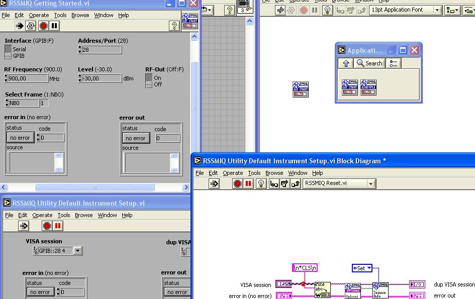
I put in schema-block function RSSMIQ (a function of the driver for my generator). I click on the RACE of VI, but compare a (red dot) interruption between the VISA ABC and ABC VISA and VISA SESSION flash icon. Why?
Automatically, it is open RSSMIQ DEFAULT INSTRUMENTS SETUP UTILITY and compare the figure downwards:
Is that a mistake? What? Why? I have fought with my generator WITHOUT ERROR?
Please see my response to your other post response No. 26 .
-
How to generate a pulse with the signal generator?
Hello
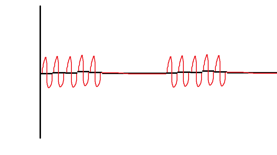
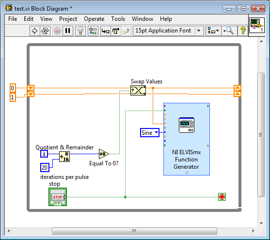
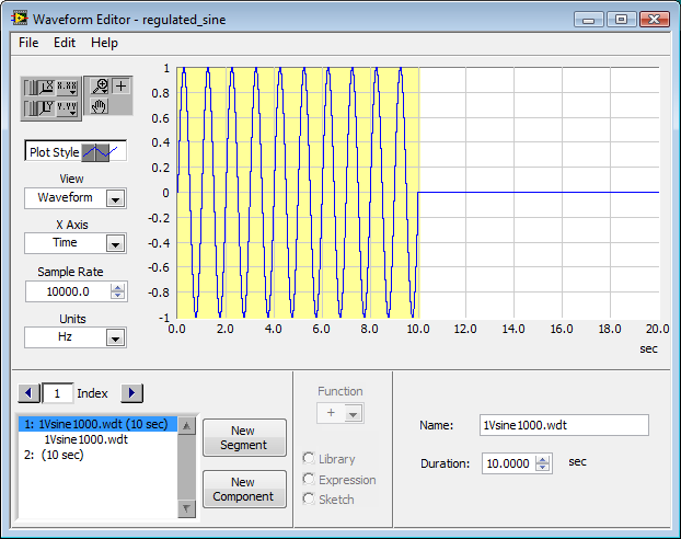
I would like to ask if anyone knows how to use the Elvis platform to generate a regulated pulse wave?
It should look roughly like the picture above. A sine wave with the regulation.
Anyone who can answer my question please respond to my post.
Thank you.
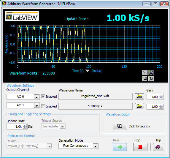
You are using LabVIEW to generate the waveform or using the Soft front panels? In LabVIEW, you can use the express VI generator function and specify the Type as "Sine". Then, simply change the amplitude of the sine wave. During the actual pulse, the amplitude would be what you want (i.e. 1 V) and while the pulse is idle, set the amplitude to 0.
If you use the soft front panels, you can use the Waveform Editor to create a waveform that includes a sine wave for the length of your pulse and then the values of '0' for the rest of the time. Then use this waveform in the flexible front of the arbitrary signal generator. Simply create a component of sine as the first part of the wave and then add another element to a level DC '0' for the rest.
-
Wait signal generator complete the scan list before sending the next command
I am writing a program for Agilent E4421B signal generator scan to list between a range of frequencies (ramp up to the maximum frequency and then back down to the original frequency) specified. The signal generator has only a list of 401 points, which is a problem when I want to wash over a wide frequency range. To work around this problem, I would like to perform several scans of list in a row. However, I can't figure out an effective way to "say" the program to wait until the previous scan has finished before sending a new order of scanning for the signal generator. Any ideas? For reference, I use Agilent ESG drivers series LabVIEW.
Thank you!
If you use standard VISA calls, I would say just that send the scan command, but add; * mutual fund? (operation ends?) make a query. Then, run a VISA to read what's coming. This indicates to the device to send a 1 to the output buffer when the scan is complete (or just about any other operation, also). As you are waiting for a response, your computer will wait the amount of time to wait so he could see a response, it is not less, your way with the exact amount of time - no more - to be actually taken.
A few warnings:
(1) make sure that the time-out is longer than the length of most slow scan.
(2) there are variants of the '1' being returned. I saw '1', '01', and even "1.00E + 3" therefore to allocate more than one byte to read."
-
[FPGA] Problem with the sinusoidal signal generator
Hello!
At first I want to apologize for my English is not my mother tongue.
Hardware and software I use is:
LabVIEW 8.5
NEITHER RIO 2.4.1
NEITHER cRIO-9014 (controller in time real CompactRIO)
NEITHER cRIO-9104 (chassis and FPGA)
NEITHER 9264 (16 channels, +-10V, 16-bit voltage analogue output Module)
I made a very simple FPGA VI: a while loop, generator of sinusoidal signal and a FPGA of e/s node in the loop. I've specified the Gnerator settings by following the path:
Frequency = 50 Hz
Amplitude = 1
Phase shift = 0.00
Size of the table look-up = 1024
= 16-bit amplitude resolutionFPGA clock frequency (40 MHz)
But the wave of "sine" I got is not what I wanted to get. First of all, its amplitude is 1 V. shouldn't it be coded on 16 bits? If I wanted to get 1V I should have specified Amplitude as a 3277. In addition, 'sine' is not very detailed, it's look like "steps", as many samples vere missing. What I did wrong? I checked the samples and tutorials, I did everything the same way. A I forgot something or not has not specify other parameters?
Thanks a lot for your help!
OK, I solved a problem. It's embarrassing to admit, but maybe this will help someone else
 I blame my inexperience
The main solution to the problem was changing calibration of calibrated RAW Mode. After that, everythoing works as expected. I had a problem with a sample because I was using a multiplier to control the generated sine wave amplitude. But... She was set to 1 in the sinusoidal signal generator. That was the reason for waveform Gradin. Please, don't laugh too much

In any case, thank you for an answer! It is now resolved
-
Application of a policy of VSG when the vector signal generator is offline?
How policies are applied when a vector signal generator is offline, make port profiles with an attached policy start VSG to abandon all traffic until the vector signal generator comes back online?
VPath and vServices configuration
The default value of failmode is close.
Fail mode specifies the behavior when the MEC has no connectivity to the service node. The default fail mode for ASA 1000V and VSG is narrow, which means that the packets will be dropped. The default failure of vWAAS mode is open, which means that the packets will be passed. service nodes vPath 1.0 does not support service chaining. When you use a vPath 1.0 service node in a string, traffic to that node goes into failure.
Thank you
Responsible Dan
Cisco IDP data center
You want to know more about how the PDI can help you?
http://www.YouTube.com/watch?v=4BebSCuxcQU&list=PL88EB353557455BD7
-
Jitter in response to signal generator of digital dashboard by using trigger nor tclk with digitizer
I've written a VI that uses NEITHER tclk to synchronize a generator (PXI-5422 named FGEN1) and a digitizer (PXI-5122 named DIGITIZER1). There is also a clock card TIMING3 generating a digital camera.
It seems that can probably be explained by the way TCLK to synchronize, but I don't understand all the details. Could someone help explain this to me?
You are right. NOR-TClk ensures that all synchronized devices start at almost at the same time, to the same sample clock, with timing very tight. Sometimes, the level of synchronization with the devices OR TClk-synchronized beats at the level of the synchronization of the instruments of some competitor channels in the same device. But this is not free, there are compromises and added additional jitter for trigger response time is one of them. Here is an attempt to explain why:
When you use NEITHER-TClk and send a trigger, the devices will respond to relax on the next cycle of the clock once made the trigger signal to the device. Let's say you have several devices all of them even configured with the same clock frequency. You block the signal of PXI_Clk10 using their PLL, so they drift out. But each unit's clock edge will be off, clock +-0.5 cycles. If you send a trigger to each of them, they will respond on the next clock cycle whenever it is, after the arrival of the relaxation to each device with different propagation times, whatever they may be. You get a single clock cycle of jitter on reaction of device to set it off.
When you use NEITHER-TClk, several things happen: all devices are locked on the PXI_Clk10 signal to eliminate drift. The device clocks are then adjusted to a period level secondary clock. Very very tight. Then a clock signal common, slower called TClk is produced inside the devices. All the generation of trigger are delayed to be sent to the next rising edge TClk, and all consumption trigger is delayed to be received at the next front descending TClk. This way you make sure that propagation delays don't mean one of the devices does not react to the trigger until the next clock cycle.
That's why you see jitter above the reaction time of relaxation. When you add devices with different clock settings, so the frequency of the TClk can be slower for a divisible frequency in the device clock frequencies everything is possible. This causes the trigger jitter of reaction time be even slower!
I hope this helps you understand what you see.
-
Hello
I want to do a continuous waveform. There are samples and files online to do it, but I would like to be able to change the frequency of signals continuously, I mean something like a function generator. I try to use the channel of PFI in NI 6221, but it provides just the waveform with a constant frequency. I wonder if it's a good idea to use the channel of the IFP? I want to give 100 kHz square wave.
Thank you
Hi Saridar
Thisexample may be what you are looking for!
Concerning
-
pulse width of measurement of signals generated by data acquisition
Finally, I would like to:
Start a counter pulse width measurement and the analog output at the same instant.
Stop the measurement with an external digital signal pulse width.My current plan is to use a digital output on the acquisition of data to synchronize a digital input and the start-up of the meter input. The digital input will be a trigger to start for the analog output. This works, except for the meter.
While trying to implement this, I tried a simple test to generate a digital pulse with the acquisition of data and wiring for counter inputs. It does not, even if it seems perfect to an oscilloscope. Then, without changing the software at all, I connect a function generator to my counter entries, and it measures pulse flawless widths.
I'm actually implemented it with a Python wrapper around the C DAQmx API, but I recreated in LabVIEW, and it has the same. VI attached. I have the latest drivers DAQmx.
Accidentally, I posted this in a forum for LabVIEW, as I managed to post with the account of a colleague. I think 2 ups live as this mandate to another post. I'm sorry. Former post is http://forums.ni.com/ni/board/message?board.id=170&message.id=389856.
Solution: I had to set the channel to counter with implicit synchronization. In addition, the sampsPerChanToAcquire must be at least 2, if not, there is an error. I still don't understand why it worked with a source of external impulse, however.
DAQmxCfgImplicitTiming (task_handle, DAQmx_Val_FiniteSamps, 2)
-
PtByPt square signal generator for output FPGA
I'm currently building a host vi in which I can choose to send a square wave or a constant value in the analog output of FPGA. I know this might solve using the square wave generator express vi in FPGA.vi, how ever, in order to save using the FPGA card, I want to use the generator function from signal square on the host vi.
The first problem I encountered was square wave generator outputs feature a table instead of a ladder, so can not connect to the output function FPGA I/O node. Then I tried square wave PtByPt. However, the functino description is a bit vague for me. What I get now is a constant value defined by amplitude instead of a square wave. If I set the amplitude to 4, then the wave is a continuous line with a value of 4, and if it's 4 or - 4 depends on the frequency I put. I don't know if it is caused by the definition of wong of the time parameter of the function.
Can someone help me understand how a square on host vi of output wave? Thank you.
Here's the same VI to 8.5. I hope that helps!
Gregory C.
-
Hello!
I wonder there is any mechanism in Labview to sysnthesis some waveforms and playing with the generator of signals 33522B.
I think that pilots have screws that can load an arbitrary wavefrom to the instrument. You should be able to modulate an entry to the unit or internal external. Is that what you are looking for, otherwise, your question is unclear to me.
See you soon,.
McDuff
-
FPGA: Change the sinusoidal signal generator
The sine wave in the FPGA palette generator, that's what I need to do
but he can't exit do 'cosine', which is outside of 90 degrees. I need 120
degrees. To avoid discouraging, I opened the façade on the sine wave
Express VI generator that turned into a normal sup - vi. I changed the
a digital constant corresponding to 120 degrees out of phase, and the name was changed
of the output pin.The module will not compile. First mistake was a wire that was a type of variable, the
Fix suggested to check a box for pre-allocating did not work so I made the table
the length constant of 1024 (that is, it is supposed to be). Following error was
that one line of vhdl file was too long (32 k characters for a specification of length 4 k max
characters).Just for grins, I put the original VI Express return with the release of cosine and
It builds correctly.There was a big damper on the modification of the vi. However, I didn't know that
simple conversion to a subvi and the tweak of a constant value would break.Is it possible to get an updated the express vi for this application, or advice on how
changing the text that is there? The compilation breaks mainly online VHDL
length associated with the range of 1024 points.I can roll my own generator of sinus by using some examples, not a big problem but
It will cost you some time. Another option might be to run two generators of sinus
and specify a different phase, but I'm not convinced that over time they
will be exactly synchronized. Change the Express VI is a much better
option.Thanks in advance,
Bill
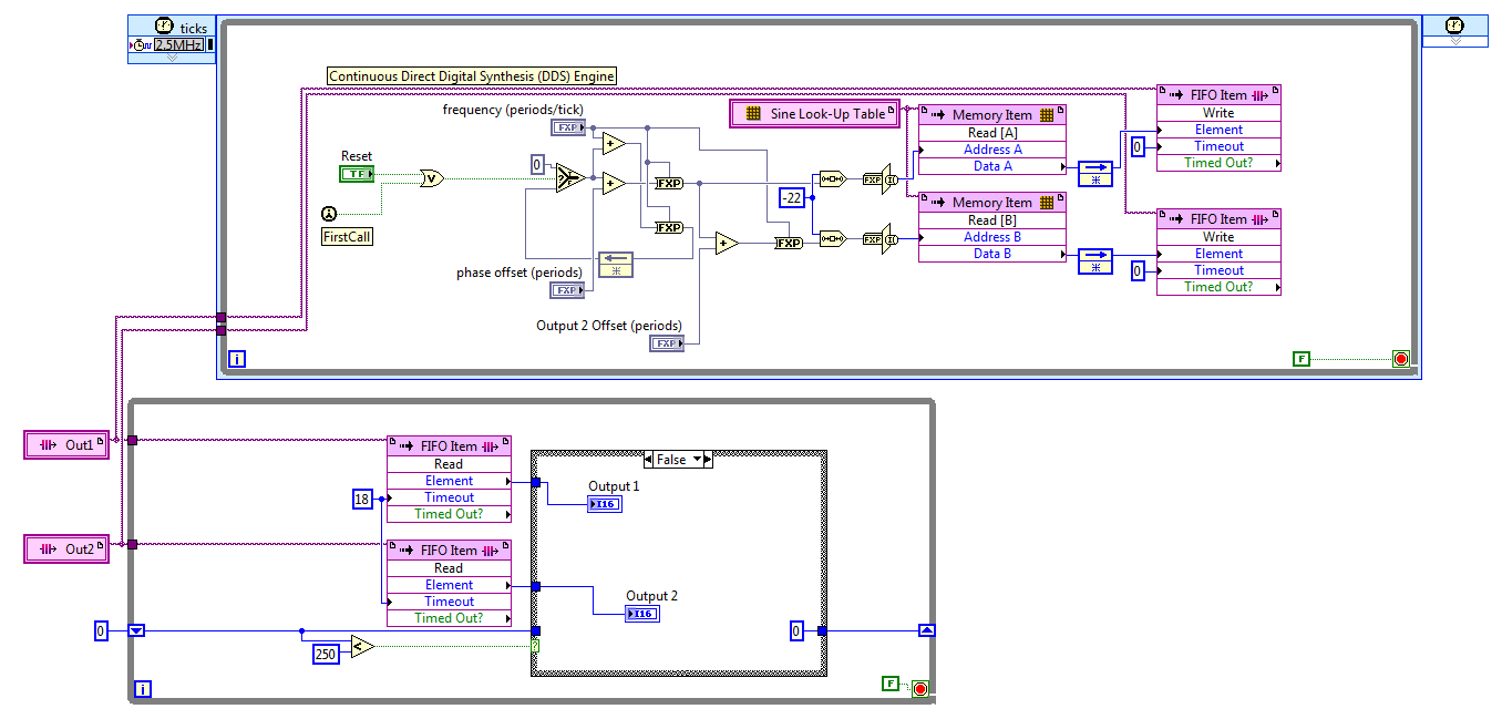
I discovered the hard way that LabVIEW 2011 has no records. After reviewing various options, I settled on the FIFO. The code presented here works well, but it is not save space on the FPGA to the wire using two generators of sinus with a phase difference in hard on one of them. For now, I'll use two sine generators, if this turns out to be unworkable in practice due to the relationship of phase adrift, then I'll look at it again.
The frequency and phase of the compensating controls are fixed point numbers formatted in zero whole bit and a 32-bit word. Bed down while the loop is synchronized with the loop timed by the FIFO, FIFO of 18 ticks timeout is two more than the 2.5 MHz in a loop which is a ditch-16. The IF block in the lower part, while the loop cut update control up to 10 KHz, 60 Hz sines more quickly.
Great experience, thank you for the help.
Kind regards
Bill
Maybe you are looking for
-
The program cannot find the execution engine
I create an executable before normally and after as a Setup program. When I try it on computer with license complete LabView program works, but if I install it in another pc, it asks me to install the runtime, but the runtime engine is installed in t
-
Impossible to update, error code 80070241
Original title: updates Hello I'm having an impossible time with wiondows updated. Whenever I try to install the updates that the error code 80070241 rises. It won't show me previous updates or anything like that either. It is said that updates were
-
Impossible to get a disc of music copied to my computer
I put in my Player library Windows Media, the classic of swoon Collection disks. (Discs 1-9 [8]) For some reason, the computer won't accept disc 8 - despite different efforts. Anyone got any ideas how I might solve the problem? John. [Original title:
-
I don't see a reference to any methods close to the database, transactions, etc. resultset in Webworks for SQLite documentation. I want to assure you that I am using device resources as efficiently as possible and I just want to confirm that there is
-
I've heard of this problem before, but am not sure of how to stop it... Client connects to the switch, switch contacts ISE on the backend. Client gets the IP address on VLAN 30 in the meantime. ISE determines the customer belongs to VLAN 60 and perfo