One look at one signal rev
I am currently trying to catch once a rev signal in the form of a square wave of 5 v, using an acquisition of data USB-6341. I have it configured as an analog voltage currently and am able to look at the level of voltage coming out. My first attempt was to take the output voltage and compared to a threshold and trigger an event from that, but I could never catch a value on the threshold. How can I trigger on a rising edge for this type of signal?
Thanks for the details, which helps a lot. I thought the camera was a configurable delay - more modern do machine vision cameras.
So, essentially, you want to trigger the camera to capture a picture whenever the time by rev signal is considered only if another condition (such as data acquisition channel exceeds the threshold) is also true at this time?
The inconsistency, you are referring is almost certainly caused by jitter of the synchronization of the acquisition software. You will get a lot more deterministic performance using a periodic trigger of material for the camera, then throw the images you don't need. The only real downside to this is that time CPU extra absorbent false images, which should be minimal. If you want a pure solution of HW, perhaps use an external Boolean AND door to ensure the time by rev signal only go through if another signal (defined by the DAQ card whenever the other condition) is high.
Tags: NI Hardware
Similar Questions
-
How to subtract one signal on the other, with the help of an oscilloscope?
I have two chaotic oscillators, which I am trying to sync. There is an oscilloscope, which channels are related to each oscillator. I need remove the signal from the oscillator-B, the oscillator signal - A, using the oscilloscope, so that I can find how much is the error between them. A - B would work very well, but there is only A + b. is it possible to do, without having to add additional circuit elements? If this isn't the case, that I would add, subtract one signal from another?
Edit: I use the classic Multisim 13.0 oscilloscope.
Hello.
You can invert the signal B-
the standard scope 2 ch a reversal for Channel B - there are 4 small buttons on the bottom of the chB instead of only 3 for chA.
Best regards
Michael
-
How can I send more than one signal to DMA FIFO?
Hello
I am trying to send more than one signal to DMA FIFO, but I don't know how to do. I have no problems when I send a signal. I try to use a DMA FIFO block for a single signal. For example if I have 3 signal I use · FIFO of DMA but when I want to wath them a table waveform signals have a delay.
How can I do to send more than one signal to DMA FIFO? and if this is not possible, how do I do to syncronizate 3 signals?
The data type of the signal is FXP<16,10>
Kind regards.
Pablo
-
Hello
We plugged a skybox until our HP omni via an hdmi cable, but I don't know how we can display the signal. Have a video converter which converts the sky SCART hdmi and it works very well on a normal TV just by changing the entry. How can we do this on the Omni?
Please read this HP document entitled ' using a game Console HDMI or HDMI video Player with your PC Omni27 " for instructions on the use and function of the input HDMI port.
-
Wireless printer when ENVY, PC keeps looking for wireless signal. Help!
After installation of the software of printer ENVY, it prints fine wireless. But, when I turn off the printer my computers appear to continue to pick up the wireless signal. Arrow and circle continue. A PC XP and Vista 2.
Can someone help me please? Having the dizziness of all this spinning. When I turn printer on it stops turning.
Help!
Hey, Hey,.
Thank you very much!!! You'll never know how much time I spent on this issue and I do not either.
I had to enter the printer software to access the scan mode, but works fine on my 2 computers and my husband.
We're going on a trip tomorrow and I just started thinking about our trip turns all the time on computer.
Thanks again, Vicki:
-
Can I use USRP 2 channels at the same time to receive a signal?
Hello world
I want to do an implementation of the time difference of arrival between two receivers (antenna) estimate. I have a kit USRP, Remora and two antennas. There is only one signal source (it is transmitted in nowhere is not serious).
Can I use two channels at the same time the USRP to receive a signal?
I need the original source signal and the delayed signal version.
Thanks a lot for your help.
Sincerely yours.
Uysal.
Hello
I found this post on the forum that can be useful for you. Looks like you can not receive two antennas in the way you describe. I think that this would require a configuration USRP two.
-
Cannot find examples of generation signal
Hello
Here is the page with information about the signal generation modules
http://zone.NI.com/reference/en-XX/help/371361H-01/lvanls/signal_generation_vis/
At the bottom of the page, there is information that these examples can be found at the following location:
labview\examples\analysis
But in my version, there is no file examples\analysis.
Where can I find these examples?
Thank you
This link is LabVIEW 2011. One of the best features of 2013 was a complete redesign of all the examples! Look here
\examples\Signal Processing\Signal generation directory -
Hi all!
I received some signals from the device. Also, I had a known standard signal. My problem is: How can I choose one (signal receiceved), which is comparable to a standard signal with the slightest mistake?The picture attached here, the yellow graph in bold is reference (standard). How to make a decision: which other graphics is the closest to the reference curve?
Thanks for all your help!
MC
This is why I post the photo, I have no 7.1 (no more), this response took more time to write code for this new thing ;-)
the mse.vi is located in the section of mathematics-statistics
the rest is digital, table and waveform
PS: the help section and search functions are the tools to look at
Congratulations to welcome
-
How can I create a record list or global signal system
Forgive me, but I've been away from LabVIEW for awhile. I worked in the field of LabWindows (99% of our work) for the past five years with some sprinkled in LabVIEW. I was responsible for designing a replacement for an existing test unit at another plant in our society with a main requirement being that LabVIEW is the development environment.
We have two architectures 'C' standard very strong that we try to use them as a reference point on the majority of our work. I would like to try to implement one of these architectures in LabVIEW but I find this part, and really a fundamental part of this architecture is not translated very well. The centerpieces of this architecture are looking for overall signal structures and a record of overall system. The research of signal structure is a complete list of signals in the system test with information scalar and offset. Registering system stores the current raw value for the each of these signals. See the examples below:
typedef struct SignalType
{
int globalIndex;
Double voltsPerEngUnit;
Double voltageOffset;
Char [SIGNAL_NAME_LENGTH] signalName;
} SignalType;
struct SignalLookup
{
SignalType sigTable [MAX_SIGNALS];
SignalType * hardwareOutSpare100;
SignalType * hardwareOutSpare99;
SignalType * hardwareOutSpare98;
...
SignalType * hardwareInSpare100;
SignalType * hardwareInSpare99;
SignalType * hardwareInSpare98;
...
SignalType * time;
SignalType * dutyTime;
SignalType * frameTime.
SignalType * isrCounter;
SignalType * softwareOutSpare96;
...
SignalType * graphPlot1;
SignalType * graphPlot2;
SignalType * graphPlot3;
SignalType * graphGo;
SignalType * graphDomainMin;
SignalType * graphDomainMax;
SignalType * graphRangeMin;
SignalType * graphRangeMax;
SignalType * softwareInSpare91;
...
} signalLookup;
Initialization functions:
void SignalTypeInit (SignalType * s, global int, char * name, scalar double, double offset)
{
s-> globalIndex = global;
s-> scalar = voltsPerEngUnit;
s-> voltageOffset = shift;
strcpy (s-> signalName, name);
}
Sub SignalLookupInit()
{
Release of material
signalLookup.hardwareOutSpare100 = & signalLookup.sigTable [0];
SignalTypeInit (signalLookup.hardwareOutSpare100, 0, "hardwareOutSpare100", 1.0000, 0.0000);
signalLookup.hardwareOutSpare99 = & signalLookup.sigTable [1];
SignalTypeInit (signalLookup.hardwareOutSpare99, 1, "hardwareOutSpare99", 1.0000, 0.0000);
signalLookup.hardwareOutSpare98 = & signalLookup.sigTable [2];
SignalTypeInit (signalLookup.hardwareOutSpare98, 2, "hardwareOutSpare98", 1.0000, 0.0000);
...
}
typedef struct SystemRecord
{
Double sigTable [MAX_SIGNALS];
} SystemRecord;
How can I translate these structures to LabVIEW when LabVIEW with global structures and tables in large n - n in LabVIEW? I am open to any criticism and help I can get.
Regards-
John OC
I'm not C code too closely, but it is seems to me that you basically have a bunch of definitions of named (structs) signal that you want to get the data by name.
Personally, I would add that all additional necessary data in there (like hardware address and the actual current value) and use a class or library to encapsulate all this in an easy to use API.
You can create the base functionality by the presence of a data value references lookup table (DVRs, which are a bit (just a bit!) similar to pointers, so that they point to specific data) that will each point to a single cluster (or object). Once you get the DVR to the cluster (or object), you use the structure in place to get the data inside the RECORDER and the specific operation you want (for example, set up the initial configuration or reading calibrate the current value of the signal) on these data.
For research, I would recommend a simple VI with a variant in a shift register. The shift register allows to ensure that the data between tracks of VI and use you the primitives of attribute ranging from keep the EVN - if an attribute with the current name does not exist in the variant, you create a new and write it in the Variant. Each attribute includes a digital video recorder, which is what you are exporting.
Thus, for every VI in your API (Init, current value of reading, etc.), you give the name as input and start calling the VI search to get the DVR. Then, you use the DVR to operate on this specific signal.
If all this seems too complicated, you can try to go with something like this - http://zone.ni.com/devzone/cda/epd/p/id/5326
-
Two timed in a single parcel sine signals
Hello
I enclose my VI, and I need help to draw the waveform.
Each symbol (0 or 1) have different frequencies. I would like to draw each signal one after another. (like a waveform of the FSK)
I am trying to build my own FSK.
So far, each signal is display one then the other.
Thank you

Hit Ratatouille,
The display of graphics for one signal after another, click with the right button on the graphic on the front and replace it with a graph in the form of wave. I think that this action has resolved the problem you mentioned. The functional difference between a waveform graph and a waveform chart is the way are handled the x-axis. For the chart, the x-axis is in real time, while for the chart, the values of x are an entry. In your case, the generation of sinuses makes the sine waves, but each generation has the same values, X, so the best you could do would be to overlap.
Hope this helps,
Luke W
-
Pxi different 2-5421 or-tclk synchronization help and reversing a signal
I have 2 PXI-5421 function generators. Screened through my vi I load a .hws file and output the same signal makers 2 all in phase and triggering the same point. I need basically to do, it is reverse one signal of 180 degrees and keep them always trigger the same starting point.
im not sure how is invert the signal on a 5421 or how to separate code so that each signal generator is separated.
Hi Liam,
I did a quick search on your issue and I think it is interesting to try to 'configure exit Mode.vi niFgen' (red border on the screenshot) and the value
output mode of entry to the "arbitrary signals" (right click on the parameter "Output Mode"-> create constant-> select 'arbitrary signals' in the drop-down list).
You could include a code of the error you found in your next reply. Thank you!
All the best,
-
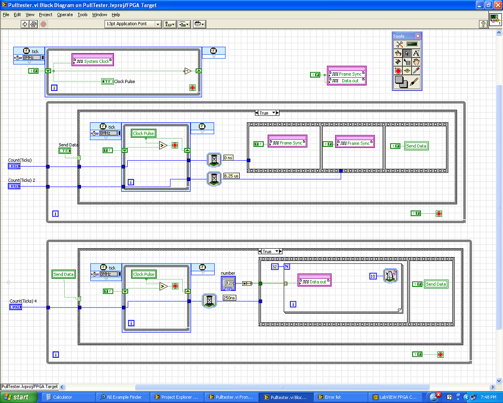
Synchronization of signals on my SBRIO problem
Hi all
I need some advice on how to complete my project.
I need to send a 32 bits of data to my unit test with the following parameters. CLK + FS + and +.
The clock runs at 4 MHZ. The FS + sends a bit length 33 of high for the treatment of the data signal, and in this context, I need to send my 32-bit data.
What I did is I created 3 loops as shown in my diagram.
1. the first loop is a loop timed to generate my clock pulses. I run at 8 MHZ with the low and high signals in loop rotation.
2. the second loop is for my frame sync signal using the rising edge of the clock over an external trigger (SEND DATA) to start the sequence. It has two red WAITING to the 0 graduation and 330 ticks (by tick is 25ns).
I have compiled up to this version of the code and run it with all the problems. I was able to generate the signal FS + 2ns after the clock rises and is to have cycles of clock exactly 33 in length.
3. the third loop which is I'll have trouble at this time is designed to loop data. I also used the pulse of the clock and the external data to start the sequence. I used one signal to WAITING to delay the start of the data by 1 clock cycle and use a loop for send data from 32-bit to 250ns (10 ticks) per line.
The problem is that I do not get the result I want. The departure of the bits is always erratic and not 1 clock cycle of delay that I hoped. Also the first bit is much too small for the 250ns.
Can someone tell me where I'm wrong? Is there another way to address the issue?
Your help will be greatly appreciated.
As a short response, I would recommend combining the three sets of loops in a single state machine. All three loops are intended to be based on the field of derivative 8 MHz clock.
As a longer answer and to explain the behavior you see... the time of the present code is assigned by the data through the areas of the clock. The details are in this help message LabVIEW FPGA: implementation of multiple clock domains with the overcoming of the areas of the clock (using a tunnel in the field to clock 8 MHz timed loop to the domain block diagram clock 40 MHz), LabVIEW is obliged to implement a hand shaking algorithm to maintain the integrity of the data. This shaky writing consumes FPGA (logic cells) tissue and takes 25ns several clock cycles to run, as well as creates unwanted delays. In addition, the third loop cannot guarantee that code data will trigger off the same synchronization signal as the second for loop because of the handshake that occurs for the data to pass through the loops of 8 MHz.
I would recommend that base you all of the communication out of a single loop timed in a configuration called a state machine. Essentially, timed with a looping structure business inside, where each picture of the structure of the case is a different State. Breast of a timed loop state machine, does not have the 'wait' function, so the delays must be implemented with a 'status quo' State which is repeated N number of times to match the time required. The following link leads to a state machine similar to the SPI communication that would be a good example for the implementation of this communication: Example of SPI LabVIEW FPGA.
The example above implemented the following communication scheme, which seems pretty close to what you implement:

This code is a little more complicated than what may be absolutely necessary to your application, but it is an excellent example of a scalable & flexible of the notion of core implementation (this code can easily be migrated to new hardware targets or add multiple replicated or modified communication to the same architecture protocols.)
See you soon,.
-
Linksys E4200 - range WUSB600N V2 / signal issues
Router Linksys E4200 dualband and Win7 64 bit Linksys WUSB600N v2.
Both in the same room, the distance is about 10 meters.
I compare the results on 5 GHz btw the stick of Linksys and btw another laptop with Intel Advanced-N 6200 AGN wifi chip.
Running a wifi 5 GHz N on the stick of Linksys, leading to the signal strength low and reduced its speed.
Practically, I can't improve the signal than the Intel + 15 to 20 dB...
Negligible:
distance / Intel / Linksys:
<1 m ="" -26db="">5 m /-50 dB /-65dB
While Intel radio affects 300 MB/s, the Linksys is somewhere around 200 MB/s only. in the same room
Anyone else knows a bad signal with the WUSB600N v2, as well? I bought the stick to stream HD media, but with - 65dB is not much of an improvement to what I had on 2. 4 Ghz, 802.11 g (())Sorry, but how is this releated response must keep the problem I described?
disable the firewall on the router spi?
I checked the possibility of automatic channel selection and channel 20-40 establishments width (automatic channel selection does NOT work correctly from either). I still have the experience that the stick has lower than intel one signal. regardless of the setting of the router firewall
-
Signal acquisition of voltage AC using NI 9206 9205 and cRIO
Hello. I have difficulties accurately acquire a signal voltage AC using a module OR 9206 and cRIO. I'm looking to acquire signals of tension of the two types of current transformers Magnelab: divide the rope and the base. In Labview, I first fill out an array of size 2 500 with the signal of the sensor (DIFF mode), and then calculate the RMS of the table. For the core of split CTs, I'm able to acquire exactly reading the correct voltage (verified by measuring the match on the line using a power Analyzer Fluke 434 amp. For the CT string, however, using the same method of table/RMS, I am unable to gain precisely the correct voltage reading. Measure the amp on the line using the Fluke 434 PA, good the CT string tension should be 0.05v. Using the 9206 (DIFF mode), the RMS of the array gives a reading of 0.071 voltage. Now the interesting part is when I measure the voltage by using two different True RMS DMM, I get two different readings. A multimeter, a Klein CL2000, reads the voltage in 0.05v. Other multi meter, a Fluke 189 reads wrong to 0.071, the same that I get using LabView and NI 9206 release. I guess the question is how the Klein interprets the signal differently Fluke 189 and the NI 9206 via LabView module. A difference between the split-core and rope CTs, is that the rope CTs require a power external power supply 12-30 v AC or DC. I'm providing 12v DC. I tried several AC and DC voltages and still get the same wrong result. I am quite sure that it is not a question of power supply, although perhaps the integrator in the rope is the creation of a single signal. Any ideas? I appreciate any input.
Thank you
J.Grant
AK2DM:
Update - found solution
-
Export of signal not cleared after erasing the task.
Hello
I'm a newbie DAQmx. Material: LabVIEW 8.6.1 with a USB-6251
I just put a Signal.vi of export DAQmx in the example of the impulse to dig of Gen. He rerouted properly to the PFI cntr0 I chose but also left the default connected.
I removed the Signal vi export and represented the Pulse.vi Gen digging and found that the IFP had routed I always responded. Can someone tell me what's supposed to happen?
More KB of aNItaB (which is a great resource whenever you are looking to export signal) note this counter output uses a "lazy uncommit' on the output terminals. Basically once you send a signal somewhere it will be routed to this line until you reuse this PFI line for something else. You can lighten the device reset routing, or just tristating line using the output Terminal.vi Tristate DAQmx.
See you soon,.
Andrew S

Maybe you are looking for
-
Is there an easy way to migrate my bookmarks from one device to another? Sorry if this question was asked before thank you for your help!
-
How can you find your restrictions password if you remember?
How can you find your restrictions password if you do not remember?
-
Hacked? Webpages look different and called Safari fake Apple number
HI, I have recently updated to IOS 9.2. A few days later my iPhone 6 has started to act weird. Safari look different and redirected web pages. I was disconnected (e) my ID Apple and when I was asked my password it was a different decision that pop up
-
How can I get my unlocked email, since he's are blocked?
so its been 2 days and still no resolution Tech eventhough say there is. my email address has been blocked, can't seem to get it unlocked... have not really solved as work important information are saved in folders and emails.
-
Error executing the call of duty 2 (entry point not found) how to fix?
When I try to run Call Of Duty 2 it pops up an error that says: "The procedure entry point _except_handler4_common could not be found in the dynamic link library msvcrt.dll." Please help me