order of node property
I have attached a photo similar to what I saw on my CLAD (I went... yay!) and was curious to know what the answer was.
Its a property node and asked at what order it runs in
choice went in the direction
top-down
bottom-up
they all arrive at the same time
his indeterminate what order
Let me know!
top-down
Tags: NI Software
Similar Questions
-
Hello
I have a simple problem.
On my side, I have a 2D chart.
I can right click and exploitation of data > empty data to clear the table.I want to do this in my entry into force.
If I do the node property or the local Variable with an empty array as input for my program initialization, it don 't work.
They are therefore, any possibility of having a property node > data operation > empty table.In advance, thank you for your help
Hey Mini,
in your init framework you write empty tables to table three controls.
When I test your VI it works as expected: all three paintings are deleted/erased...
What else do you need?
But as said before: you use two shift uninitialized registers. It would be really useful to initialize - using the same empty array constants!
-
disable the node property problem
Hi all!
I want to do a VI that the user will not fool around with the button.
So I put in my case for the "change the value" event, a node property disable during 1 second (disable) and out of it, an enable.
The problem is that if I press the as button 3 times in 1 second, the button will still change the value 3 times, as he has memory.
I want to just the user to be able to make changes to the value only after 1 second and not save them. I hope I made myself understood

Are there any suggestions?
You may use a state machine with two loops. UI loop place the actionwith a timestamp and the loop of consumer can compare timestamps to decide if enough time has passed, or if the action should be discarded.
-
all the nodes property objects and objects grouped
Hello
Now position an on my GUI objects in the center of the screen using nodes property. However, I don't want to have to have a node property for each decoration, image and control. Is it possible that I can group all the objects and then use a property node to position them? I tried to use the property node all objects, but none of the clues seem to apply to my group of objects.
Help please!
Thank you very much.
John
p.s. I downloaded my vi test. The graph, the decoration and the exit button have been grouped. control over check.vi to set the object to be moved.
Tabbed pages are a great way to group objects GUI.
Rather than use a decoration,
- use a tab control
- Delete everything except the first tab
- Hide tab
- The value of the proprties of the tab control and control on this page is move, hide, display as well as the tab control.
I hope this helps,
Ben
-
Node property accessor vs LVOOP
I spent my CLD and exploring the world of LVOOP. I am a mechanical engineer with about 1.5 years of experience in LabVIEW, so I still have a ton to learn.
While browsing through the LVOOP, I ran across things that I can't reconcile.
When is the right time to create an accessor for a property of a class method and what is the right time just use a node property to get or set a node of class?
Data class must have all children data parent instantiated inside more his own? Or does just have its own data? (that is, if the parent has child Name and Value, should he Name, Value and amount or quantity?)
Can anyone provide an example of Composition as a class relationship? I understand the LVOOP class training that the Composition is a "has - a" relationship, but I'm still not sure what this means in reality in the real world.
Any help is appreciated. Thank you

Welcome to the object-oriented approach.
When is the right time to create an accessor for a property of a class method and what is the right time just use a node property to get or set a node of class?
I used to always create accessors and it is advisable to do so. Technically if the accessor is private (which means no VI outside the class can call) and you don't need to do any checking of range or any other logic on a read or a write and your class is not to have children, then you might get away with just using a ungroup by name (using a property node requires creating an accessor - the property node is just syntax to call the accessor).
An accessor allows you to:
- the scope of access (i.e. which is able to access these data, data of class being always private in LabVIEW)
- error checking or conversion to centralize code
- protect code against changes how store you a value (as long as you can write an accessor which returns a value in the specified format, the way the value is stored internally to the class will not affect the rest of the application)
- have a single point to debug
Data class must have all children data parent instantiated inside more his own? Or does just have its own data? (that is, if the parent has child Name and Value, should he Name, Value and amount or quantity?)
Not if you use accessors to get data from parents. Because the child inherits all methods of parents, he can call the parents of the accessor methods. Recreate the fields Name and Value of the child class would be exactly what OO tries to avoid duplicate work.
Can anyone provide an example of Composition as a class relationship? I understand the LVOOP class training that the Composition is a "has - a" relationship, but I'm still not sure what this means in reality in the real world.
Of course, take the job template DAQmx for example. A task class contains information of calendar and 'a' one or more channels in. Each channel can be it's own class that represents the type of measure and scale for this specific channel information. Given that the task class contains an array of classes of channels that have no use outside the context of a task, then you have a composition relationship.
Hope this helps clear things
Simon
-
Nodes property and rings of Menu
So I have this multimeter I need to make a driver for, and it has so many modes/scales of operation it will be a pain.
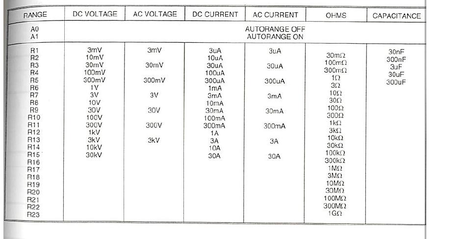
So that's what I'm working with, there are a lot of 'functions of measure', including the tension continues, alternating voltage, current DC current alternative, etc, there is more than what is shown in this picture, but functions are the first row in the table above.
Associated with each function is a set of ranges. GPIB codes for each range are on the left most column, and you can see what they are in the other columns.
To manage the functions of measure and the beach in this driver I have, I'll use 3 sub.vis:
The first sub.vi is very simple, consisting of a ring of unique menu, a number to string converter, then a concactenate string, shown in the first attachment. It sends the command of the unit function.
The third sub.vi is also quite simple, it sends the range control to the device. This is the sub.vi between the two that I need help.
What I want is to have a single control of the range , in the form of a ring of menu, and the 2nd sub.vi reformatted this menu ring. So what I need is to use a property node to set the line items in the ring menu to match with items included in the 6 columns above, so that if the function is chosen to be volts DC, the menu range ring will show 3mV 10mV, 30mV, 100mV, etc etc, but if the function is chosen to be alternating current the menu range ring show 3uA, 30uA, 300uA, etc etc.
The other tricky part of this is that the voltage and the current functions of the AC pass range controls (see how there is no range associated with orders R2, R4, R6, etc.).
That I'll probably be able to come up with something clever to treat (as simply double the value coming out of the ring and incrementing it with a + 1 on these functions to make them all odd), but for now I need help in the form line items in the menu ring.
Attachment 2 was my first attempt to simply edit the line items in the menu ring. Unfortunately the way it is put in place, he crams this whole string them in 1st command line, rather than separate. I don't know how to change one of the elements of the past that 1st menu ring.
Hope I explained quite well, make me know if I need to be clearer.
You use the wrong property. The property to use is 'Strings' and the entry is an array of strings.
-
Use the node property to get the value of control
Hi all
I know that you should keep the use of local variables to a minimum in order to avoid race conditions. Is this the same problem if you using the eg property node. a digital control?
The reason why I want to do is to keep the son of the intersection when I need to use a control on one side of the diagram across the diagram...
Basically to make the scheme simple and enjoyable to watch.
I hope that makes sense!
Good day!
Kind regards
Tommy
Tombech84 wrote:
[...] Is this the same problem if you using the eg property node. a digital control? [...]
Exactly. Perhaps, he creates the race conditions and should not be used. Using wires to connect the terminals is the approach only "Save".
In addition, performance decreases in the following order:
-Terminal (+)
-variable (0)
-property to value node set (-)
Norbert
-
typedef red dot coercion cluster with node property value
Hello!
I have a project more vast, where I have parallels of DAQ and other calculations. In the project that I have spend all my relevant data between different parts of the program by using a typedef cluster control, so if I need to add the new element, it updates everywhere in my project. My problem is, when I want to update the items of this control on the graphical interface of typdef in what concerns changes in different places in my program, I use the property for this node. It works normally, but sometimes, I get a really strange behavior... sometimes the enum element not updated and so on...
I have attached a simplified version, only including the party concerned...
No idea what I did wrong?
Thank you very much!
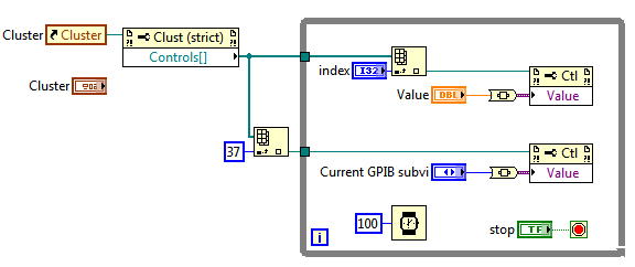
The attached file and the picture shows a way to write about the control with nodes of property.
Run the program. You can change the "current GPIB Subvi" selection or select a control (via index) and set its value.
You can use a def enum type to select the desired control if you know that the order of the controls will not change.
Steve
-
Node property/reference for the image and 'Create VI' inconsistent control?
Hello
I encountered this problem several times already and although I have worked around him, so far, I would really like to understand what is it:
If I have an image display control on the Panel before (IMAQ Vision, not the image control type) and drag a property node or a reference to it on the block diagram, it seems impossible to create a Subvi diagram if the selected objects are equipped with a knot of property image or an image reference. Select 'Create Subvi' won't do anything, don period. No warning, no beep system, no nothing.
A related issue is that if I have a view control reference on the diagram and try to create a control from it (for example to use as a control on one dimension of connector VI entry), same thing, "Create control" will not do anything.
Why is this?
Thanks for your comments.
X.
Xavier,
This was reported to R & D (35835) for further investigations. A possible workaround is to make the Subvi LabVIEW 7.1 and open it in the new version of LabVIEW.
-
Hello
I m using a camera GigE (DFK23GM021) and im trying to put for example the brightness.
I would like to know how the work of property nodes and how can I get the names of attribute/chains I put in the nodes.
Thanks in advance.
the camera im using does not support property imaqdx nodes, instead I use nodes in the Active X for it to work.
-
a node property to return the configuration of the task a DAQmx
Tasks in this project are preconfigured in MAX, but once the operator needed to enter and change the sampling frequency, that I would like to add a routine to start to check the sampling rate of the configured tasks. I know that using a DAQmx property node can return task names and channel names, but what I could use is a property node to return the sampling frequency of the task. A knowledge of a way to do this?
If you place a property on the block schema node, connect it to your task control. Right-click on the property node, and then select the DAQmx Timing (class select DAQmx-> DAQmx Timing). Then select the sample-Rate property > clock.
-
Boolean switch node property in the Sub - VI
Hi all
I have a main vi and one under vi. In my Subvi, he gets a Boolean value from the main vi through property node (see table). The Subvi queries the Boolean reference until it gets a real. Apparently, when the Subvi is running, it is not detect changes in the Boolean main vi. Why is this?
If it's a Boolean latch, you will get error 1193 whenever you try to read its Value property. I noticed that you are not checking the output of the reading the property value error, this is why I guess that's the problem. Read/write, the Value property of a latch that Boolean is not taken in charge. You will need to pass the Boolean value to use the mechanical action switch... or you will need to find another way to transmit information between your screws
For more information on the mechanical action of Boolean values, see this help document.
-
Connecting the node property programmatically to objects in front?
When I right click on a property node, I see the option to connect to any object of front panel.
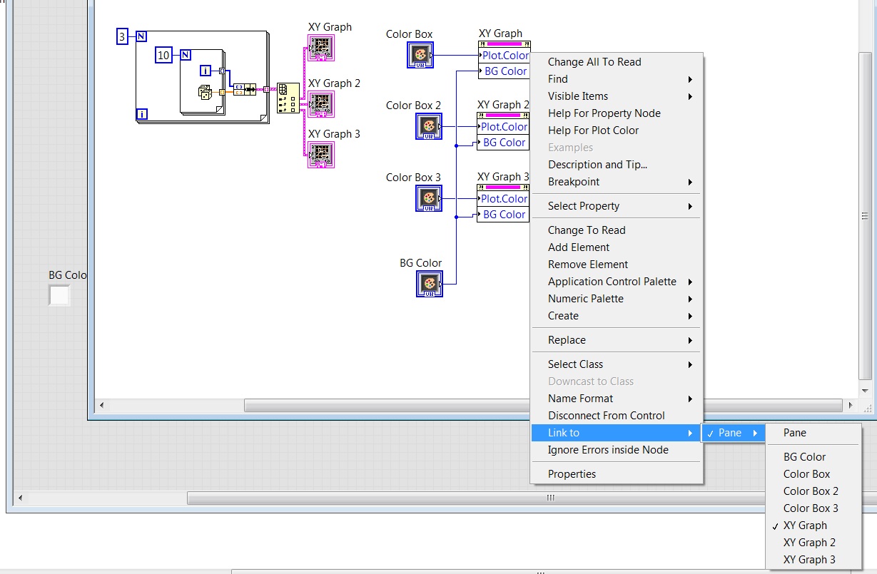
Is it possible by programming? I create three charts XY and I want to know if I can control
the color of terrain for all three charts XY with creating ONLY a property node (color graphics) and placing it inside a loop for
and for each iteration of the loop for example, linking the property node to different XY graphs.
See the image.
Hello
what you can do is to select the option 'disconnect control' when right clicking on the property node (it becomes a generic property node to pass a command reference XYGraph), place this property node in a loop for, before the loop, build an array containing references to your 3 XYGaphs (right click on each XYGraph > create > reference).
Hope this helps
-
Hello all;
I want to do my most powerful .vi, so what I wanted to do are the following:
1. my entry should be: "checkbox system Boolean" table 1 d (it's must have, I need this as input in the function call library node)
2. all these checkbox (12) are connected to the graph (in this example, I chose 12 graphs and a signal input which is the same, in real time, I have different signals, the scales...)
What I wanted to do when I check the first box, first graph will appear (and on the graph will display its name, which is identical to the box). And then for example if I choose will be 3,5,8 checkbox graphic 3,5,8 which will follow one after the other and so on;
I started making table 1 d box, but after I group all together and try to rename it for example check box 1 for channel 1, is to change all names not only those who I have renamed it. I know that I can use 'property node' and choose 'visible' and 'value', but I don't know how to implement together and also move graphic one after the other, if I choose for example 1,5,8 channel.
I attach test file and photo;
Thank you
Look at this.
This makes the Cluster to table as I talked earlier and locates also each chart based on a table of positions.
-
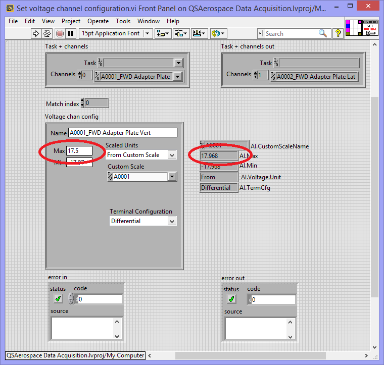
Writing to the nodes property DAQmx channel does not refresh the channel values
Hi all
I have a riddle. I created a task programmatically in LabVIEW and programmatically added several analog input channels to the task. It's easy.
I wish that my user must be able to modify the individual channels within the task. To this end, I created a set of screws that allow it to change the settings appropriate to the channel (for example, if it is a channel of thermocouple, it can change the type of thermocouple, CRC value, etc... If it is a strain gauge channel, it can change the coefficient of fish and so on). These screws all works beautifully, like the VI where they live.
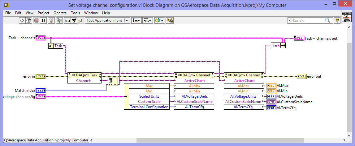
The specific question that I have is that writing to the channel property nodes refreshes not communication channels. See the images below. The first image is the code that needs to define new channels of communication:
Note that immediately after setting the property nodes, I read their values back, just to see what comes out back.
The second image is an image of the public Service immediately after the execution of this VI. Note that the values read from the channel property nodes did not updated to match to the set of values, but instead kept their initial configuration values:
What I am doing wrong? I fought this for a few days now and I'm stumped.
Thanks for your time!
Diane
Hi, Diane. A week ago, I also had a problem changing the channel properties (not sure that our situtions are exactly comparable, but...). My 'solution' to want to change the appearance of the task was to just throw the original task and recreate all the elements of the task from scratch.
I've not done enough 'experiments' to work when you can and cannot change, but am now much more cautious...
Bob Schor
Maybe you are looking for
-
Automatic wifi connection does not
Since the update to El Capitan, my laptop is no longer automatically connects to my wifi at home on the opening of laptop after sleep (it does not connect because it shows an IP 169.x addy, i.e. internal) - I have to disconnect from the network, then
-
E545 think more that his battery is a lenovo authorized
If one day my computer gives me this message when I start: "this system may not support makes Lenovo not authentic or batteries which are allowed. "The system will continue to start, but may not charge batteries not allowed," he said. I don't know wh
-
I just put a dvd in my player for the first time and it makes a winding noise / rattling during operation.
-
Microsoft made a habit of you personally call by phone and saying: you have malicious software on your computer? Whenever they asked me to go to my computer and go to the Control Panel, they will say to me then my serial number to confirm that it is
-
When I try to install the drivers under sound and also imaging devices he returned with access denied and the code 28 error and said that the drivers for this device are not installed.