output of a wave in U8 using NiDAQ USB-6009
Hey
guys im trying to output a sine or square wave in U8 format using NI Daq USB 6009, I'm a kind of a release, but I don't know if the law or the not.please help me check, am doing some kind of a blunder that correct me please im fairly new to labviw.
I'm waveform.vi Resample dt varied my value of th also.but requirement what outputs does not match with the value/s enter the loop.
Tags: NI Software
Similar Questions
-
Why is the selection of the mode disabled in max for NIDAQ-USB-6009?
I try to use NOR-USB-6009 AO to generate the sinusoidal signal.
(1) I want to use MAX, but the selection of the mode and frequency are all disabled in the "Analog output" section
(2) I find a VB example to generate the sine wave, but I received an error message.
I want to know if the OR-6009 function support limited or not...?
The attachment includes the screenshot.
Thank you very much!
Kevin
Kevin,
Yes. Timed software means that the appliance has no internal clock or the buffer. You call the AO write with data point. Then you call AO write later with another data point. Repeat until cooked. This means that the maximum rate of update of the AO is approximately 100 hertz or a little faster. It also means that there is a lot of jitter of synchronization due to latencies of the OS at speeds like that.
Think about AO on the USB-6009 case as a parameter Variant sometimes of continuous tension for your system.
Lynn
-
Recommend components for the plant of thumbnails that will be automated using NI USB-6009
I build a treatment for a University project and I'm looking for a few recommendations of components that work well with the NI USB-6009 case. Because of what is a project of the University, my budget is $ 100 and I need the following:
a float switch or something similar
a solenoid valve two-way or three-way
a pump
a pH sensor
a temperature sensor
a camera
I understand that I may not have a sufficient budget for all these components, but all product recommendations would be appreciated.
Hello
I recommend using the following tool to see examples of projects other users worked on in order to determine the appropriate components: http://www.ni.com/examples/
I hope this helps!
-
motor current by using NI USB-6009
Is there a way to measure current of a motor with the NI USB-6009 case? I understand that I must use I = V/R. But it seems that with this concept, I would have losses for the engine, so I used a small resistance and measure the voltage across it. I'm trying to get a reading of the Spike current with a voltage to an engine No. Thanks for the help.
-Nick
The shunt would be just to go online with the engine and measure the voltage drop across the resistance.
Eric
-
The best way to channel multiple steps using NI USB 6009?
I'm new to labview and I am trying to acquire multiple voltages of several channels and spread them out on a chart. It seems impossible to do it at the same time since the NI USB 6009 has only one pair of ADC.
The only way I ever came with is to use daq assistant to support significant tensions one by one and then make it loop awhile, but y at - it any delay during the move between channels?
And there at - it of best ways to acquire data from multiple channels?
If you have specified multiple channels (i.e. Dev1 / ai0:ai3) with a single DAQ Assistant, then this is the right method. The inexpensive device has no simultaneous inputs, so you will have to live with the slight delay of channel inter.
-
Is it possible to collect 16 channels of analog data using 2 USB-6009?
I got this error when you try to read voltages of 2 USB - 6009 s:
Error-201426: one or more devices do not support multi-equipment tasks.
John
Create a separate task for each device.
-
Pull-up external USB-6009. digital output (open collector) allows onboard external + 2.5 V output?
Pull-up external USB-6009. digital output (open collector) allows onboard external + 2.5 V output?
Hello
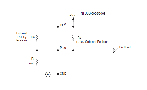
I want to config output digital USB-6009 to + 2.5 V above and 0 V digital output low. I know I can config USB-6009 digital output open collector with resistance to pull-up external, that can be applied with + 2.5 V power source.
My question is: can I use USB-6009 Board + 2.5 V output as the current source of resistance to pull-up? What resistance is a good number for the resistance to pull-up, if I can use this configuration?
Thank you much for the help.
Cathy
Hi Cathy,.
The digital USB 6008 front-end server looks like this:
So, there is actually an internal pullup to 5V 4.7 kOhm resistance when the device is configured to open collector.
If you want to display 0 to 2.5 V, I would look in a resistance of polarization of 4.7 kOhm between c and ground (according to the rest of your tour).
Best regards
-
Can I use two USB 6211 to replace a USB-6009
Hello
I got a labview vi., 5 output channels digital, 2-channel digital input, 2 analog inputs are necessary for the execution of this vi. Initially a 6009 usb is used to run the vi. But I have only two usb ports 6211 now, which has digital to digital for each data acquisition 4 inputs and 4 outputs. I wonder, can I use two usb 6211 to run the vi. ? What should I do?
Reverse lines are wrong, does that mean it will display 0 for false and 5 V 1.
Active drive is the normal mode of the digital output: it generates tension when said.
I forgot one thing: that you are behind the wheel of these lines, how much power do you need?
Analog output is less powerful, it can give only 2-4 mA, while the digital output 6009 could give 8 my.
-
Is it possible to a floating voltage with the output box usb-6009?
Hello
I was wondering if anyone knows how to a difference in voltage output 0 to 1 AO on the box USB-6009 DAQmx AO without reference to the ground. Any help would be greatly appreciated.
Thank you
Bryan
Hello
Page 19 of the manual USB-6009:
http://www.NI.com/PDF/manuals/371303l.PDF
Shows the internal circuits of the DAC are referenced to ground so there is no way to internally isolate it / provide any reference.
Maybe there is another way to make the desired effect? I don't know the details of your request to suggest everything.
Please do not hesitate to ask questions
-
Using the NI USB-6009 case to generate a 12VDC output and output current of 300mA
Hello
I use the OR-USB-6009 my power supply for a 12VDC with drive current of 300 solenoid my. Initially, I used a non reverse Op-amp circuit and Inverter circuit operational amplifier to get the + 12V and - 12V output but I could not get the current I required. Should I use a transistor?
Please find attached photos. Any input would be appreciated.
Thank you
Adam
Well, really depend on your piercing circuit. But I used most systems use the transistor to set the voltage of the device to 0V. So when your DIO is high, the output is actually 0V (low). So using a converter chip, your release of the DIO will be sort of the output circuit. If you get the right IC, then the inverter will give you also a few extra current to drive your transistor.
-
How can I measure the output of a sensor pwm ultrasound using the module or 9403
How can I measure the output of a sensor pwm ultrasound using the module or 9403
Khalil,
When you say 'measure' the PWM signal, exactly what to tell you?
You're looking to measure the frequency or cycle of the signal function? You count the edges of the PWM output increase? Looking to control the waveform?
With reconfigurable FPGA hardware, it is up to the user to define the function of the physical i/o on the FPGA chip. By connecting the signals as Adam suggests your digital pulse will be brought to the cRIO. In your FPGA program, you define the function. You can set a base counter or transfer digital data from single point to welcome you cRIO for floating-point more complex treatment. Example FPGA programs are located in the http://www.ni.com/IPnet.
Hope this helps, please post any additional questions.
-
USB-6009 slow output signals using SignalExpress - error 200077
We have a Council of USB-6009 and Signal Express version 3.5.0
We want to generate low-frequency, analog and digital outputs to simulate some slow movement process.
We have created the signals and their generated as output, put when we RUN the project, we get error 200077, which seems to indicate that we must use On Demand distribution of signals.
If we choose On Demand, then the generate DAQmx says we have a missing entry.
So, what method should be used with the slow USB-6009 to generate box (.01Hz and slower) analog and digital outputs?
These are 2 of the projects, we tried - using On Demand, N samples, continuous, internal, and external triggering etc..
Thanks adavance for your help...
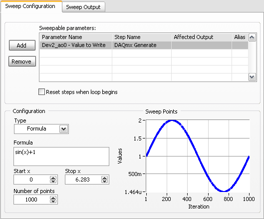
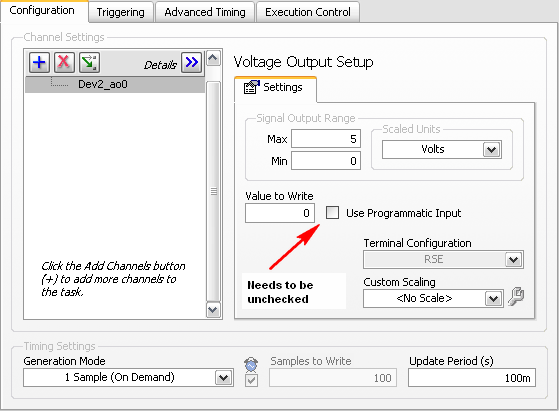
Welcome to the forums of Steve,
I have good news for you. I played a bit with the sweep and actually got a code facing up to generate a slow signal. I went and tested it with the 6009 and he was able to run without any errors. I joined here, but if you have to open (or anyone else in the future), here are some screenshots of how it works. If this works, feel free to make the forum as resolved while others can locate a solution a little easier in the future.
Scan Configuration:
DAQmx Config:
-
With LabVIEW how to control an instrument with a RS232 output, using a USB RS232 converter cable.
With LabVIEW how to control an instrument with a RS232 output, using a USB RS232 converter cable, since I do not have rs232 ports. I have two instruments I want for the control in this way. One is a guarantee of strength Imada SPAS with RS232 output. The other is a micrometer Panasonic HL-G103-S-J laser sensor which is RS422. I have done significant programming LabVIEW using GPIB, but I have no experience with devices such as these. No matter what tutorial or examples would be greatly appreciated.
Thank you.
When you plug the USB-RS-232 converter, it installs a driver under Windows which makes it look like any other RS-232 port. You may need to install the driver of everything that came on the CD with the converter. It will get a Com as Com5 port number according to what is the next available number.
-
Output analog, the USB-6009 case - can I use DAQmxWriteAnalogScalarF64?
I just got a NI USB-6009 and I try to use the outputs analog simple.
I'm running on a Mac, so I'll try to use the API OR-DAQmx Base 3.2 C (downloaded from here: http://joule.ni.com/nidu/cds/view/p/id/1078/lang/en). This is the most recent version of NOR-DAQmxBase, I could find.
I try to do continuous analog output on the 6009, which does not have a built-in clock. I was hoping to do the sync software and just new output values when I want to.
I can't get an output of database to work. Other messages and the example of Windows files, (e.g., National Instruments/NOR-DAQmx Base/examples/ao/MultVoltUpates-SWTimed.c) it seems that the best thing to do would be to use the DAQmxWriteAnalogScalarF64 function.
However, this is not in the Mac version of the C API of NIDAQmxBase. There is actually an entry for this in the NIDAQmxBase.h file, but it is commented out. Anyone know why? Is it possible to use this function for the analog output on request on Mac?
Thank you.
Clement
I have NEITHER-DAQmx Base installed 3.2 on a 10.4.11 system. One of the examples files 'genVoltage.c' calls DAQmxBaseWriteAnalogF64. I was able to compile and run this example with a USB-6009.
The DAQmxBaseWriteAnalogF64 function would work for you?
My guess is that, since you can write a scalar value with DAQmxBaseWriteAnalogF64, DAQmxBaseWriteAnalogScalarF64 becomes superfluous. The example provided with the installation shows how to write a unique value (i.e. scalar.). I pasted the code of OR below.
int main (int argc, char * argv [])
{
Task settings
Int32 error = 0;
TaskHandle taskHandle = 0;
char errBuff [2048] = {'\0'};
Channel settings
Char [] = "Dev1/ao0" chan
float64 min = 0.0;
float64 max = 5.0;
Sync settings
uInt64 samplesPerChan = 1;
Writing data parameters
float64 data = 3.25;
pointsWritten of Int32;
float64 timeout = 10.0;
DAQmxErrChk (DAQmxBaseCreateTask("",&taskHandle));
DAQmxErrChk (DAQmxBaseCreateAOVoltageChan(taskHandle,chan,"",min,max,DAQmx_Val_Volts,));
DAQmxErrChk (DAQmxBaseStartTask (taskHandle));
DAQmxErrChk (DAQmxBaseWriteAnalogF64(taskHandle,samplesPerChan,0,timeout,DAQmx_Val_GroupByChannel,&data,&pointsWritten,));
Error:
If (DAQmxFailed (error))
DAQmxBaseGetExtendedErrorInfo (errBuff, 2048);
If (taskHandle! = 0) {}
DAQmxBaseStopTask (taskHandle);
DAQmxBaseClearTask (taskHandle);
}
If (DAQmxFailed (error))
printf ("error in DAQmxBase: %s\n",errBuff); ")
return 0;
}
Hope this helps!
-
I am not able to install driver of mx NIDAQ (for the use of USB-6008) in my laptop,... well NIDAQ902f0 want to give any suggestion...
 Following message comes when I run the Setup... (installation program downloaded from the website OR..)
Runtime error:
This application has requested to terminate in an unusual way.
Please contact the application support is more information.
Title of the dialog box is "Microsoft Visual C++ runtime library"
Is the same when NIDAQmx 7.5 is tried to install from the CD that came with the USB-6008.
Maybe you are looking for
-
Toshiba laptops work well with Linux?
I'm a big fan of Toshiba, but it's the last time I buy a Toshiba product. Producing none of Toshiba laptops running Linux? Least toshiba engineers could do is to make sure that a live ubuntu cd works on the laptop, to make sure that the fan starts an
-
I can make a presentation of Keystone on iphone 6 using the AV connector in area no wi - fi?
Can I make a presentation of Keystone via the AV connector + 6 iphone offline?
-
can ii put a ringtone of notification on my emails
-
I've updated the Mac driver for the 8600 and direct wireless printing is no longer works. V5.9.1
I've updated the Mac driver for the 8600 and direct wireless printing is no longer works. The HP utility is v5.9.1, Mac OS x 10.7. I did the software update and a new driver HP was part of the package. HP ePrint still works, and print tests are okay
-
How can I report a hacker on my email account and find the IP addresses for both weeks
My email account and my social network has been hacked. All emails have been deleted, but I was able to retrieve emails and realized my facebook and paypal account had been or tired to be hacked as well. I was wondering how I would make this and it m