Output TTL triggers analog input with PCI-6251
Hello, I'm new to LabVIEW and have a question that I hope I can get a response on this forum. I am currently using a PCI-6251 DAQ card with a block of connection BNC-2120. I would like raise an event on an input, for example a sine wave, which is connected to AI0 analog. Then I would send a TTL pulse train via the digital output. What I'm describing can be better understood by the images of this link:
http://zone.NI.com/DevZone/CDA/tut/p/ID/3017
In the tutorial page linked above, they do mention the card PCI-6251, but when I read the specs and compared, 6251 also has analog and digital Board, trigger functions, as well as digital I / Os... so I think he should be able to do what I want it to do. Can anyone confirm this? If anyone could help me by providing a VI that could do what I ask, just to help me get started, would be greatly appreciated. Thank you!
Hello!
Please post on the Forums OR! My suggestion would be to use build it digital Pulse - Retriggerable.vi found in the Finder for example of OR. Open LabVIEW, go to help > find examples > input/output equipment > DAmx > generating digital pulses > generate digital Pulse-redeclenchables. Change the type of trigger for this departure vi > Analog edge and make the source one line APFI (pin 20 of your card is APFI0). This will generate a pulse based on an edge similar to a level that you specify.
I hope this helps!
Tags: NI Software
Similar Questions
-
Problem with a precision of analog input on PCI-6111
Hello
I'm reading an analogue signal which varies from 0-11 V using a card of acquisition data PCI-6111. The signal comes from a Tube set (PMT) which is part of a microscope configuration, so it is very important that the resolution of the analog input signal be as wide as possible generate quality images. According to the data sheet for the PCI-6111, the analog input resolution is 12 bits, which should correspond to a sensitivity of ~2.686 mV for my voltage range.
To test this, I set up a task to analog input with a 0-11 V voltage range to read samples of an analog output, which I wrote a simple waveform. Since the 16-bit analog output resolution that I assumed that it would not limit the accuracy of this measurement. I have attached the VI I used for this measurement below. The analog input data are saved not truncated in a text file.
Analyzing these data, I found that the real input sensitivity is ~9.766 mV, corresponding to levels of voltage exactly 1126,4 and ~ 10 bits.
Is there a reason why the resolution of analog input is much lower that it is indicated on the card? What are some of the ways I could improve the sensitivity of this measure?
Best,
Keith
Sorry, when you mentioned the specs, I thought you already had them. If this did not come with your Board of Directors?
-
6009 outputs digital and analog input synchronization
Hello
I work in a program NI 6009. I want to leds by car with outputs digital NI 6009. For example, leads first will be on until what 200 micro seconds then second led will be on up to 200 micro seconds, and then first of all led will be on up to 200 micro seconds. I'll take led with photodedector signals and connect analog output photodedector input NI 6009. I want to synchronize the outputs digital and analog input and separate the first and second led signals the analog input for NI 6009 channel. How can you do with NI 6009? Please ADV
You can not do with the USB-6009 case. Its outputs digital are software with a maximum speed of slightly more than 100 samples per second. The outputs can produce 200 microsecond pulses and cannot be synchronized with the analog input.
You need a device with outputs digital hardware timed or counters that can produce a pulse outputs.
You can synchronize a bit digital output and analog input recording signal on an additional channel to HAVE. Will allow you to see the photodetector and LED the drive with the same schedule and such resolution as described by the sampling rate I. The maximum sampling frequency of AI on the USB-6009 case is 48 kHz that is shared by all channels. If you have two lights to led and photodetector two signals maximum sampling rate would be 48 kHz/4 = 6 kHz which is barely fast enough for your 200 US signals. For more than 4 channels, it won't be fast enough.
I suggest a simple oscillator circuit building and use it to clock a flip flop. This will give you alternating signals to drive the LEDs. You can use a line to reset the flip flop to give you control without the need for high speed.
Lynn
-
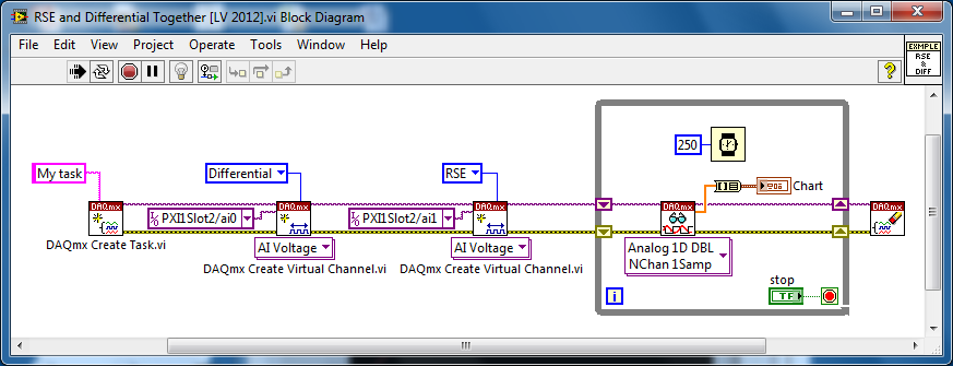
Several analog inputs with different configuration differential/CSR
Hello
Can anyone tell how to measure two analog inputs with different configurations using a USB-6009?
I am aware of the syntax for create virtual channels for the channels DAQmx create virtual so I created two strings using Dev3 / ai0:1 but I would like the first string of the CSR and the second to be differential.
So far I have found no way to specify the configuration of the separate channels.Any ideas much appreciated!
Jack
JackT wrote:
I prefer to use the 'low' level vi is therefore always curious to know if there is a way to set the configuration using the their.
It should be like this:
-
analog inputs with outputs analog delayed
Is there a straightforward way to configure Labview as a generator of analog delay? I need to generate an analog output that is identical to, but delayed, an analog input signal. The delay could be quite long, on the order of a second or two. I'm using Labview v8.6 and I have a card PCI-6251. Any help would be greatly appreciated.
Kind regards
Stephen
Hi UKslj,
I went ahead and took a stab at it - how does this look:
Use delayed output Version of avian influenza in DAQmx AO
The downside is that you need to set delay high enough so that the task of the AO is not negative, but I think it should be more or less what you need to do. Let me know how it goes!
-John
-
Blocking of blue screen with the analog voltage (WinXP, PCI-6251)
Hello
I'm looking to solve a problem of blue screen with my measure blocking
application, which I am developing with C++. Blocking seems manifest
a little random after a variable amount (500-50 000) of voltage analog
measures. My application needs to make a huge amount of these digitally
trigger voltage measures after a certain period of time, and I'm using a
unique
task to do. The task is stopped and started after a single measure
is
which is done around 10 000 - 100 000 times per second. For this
because I do synchronized with the PCI-6251 map data acquisition and
one
Ztec oscilloscope card. It seems that the probability of blocking could be
associated with
the frequency of measurements of voltage that I perform.The
the app itself is multithreaded, but I'm blocking concurrent access
TO
the card with lock - all access to the card are behind a single mutexlock, so simultaneous access is blocked. In any case, all data acquisition
access
o the map is initially a single thread, which is dedicated to the acquisition of data
operations.I also did stress tests with Ztec scope map, which does not
result
in all the problems. I also disabled in order of acquisition of Ztec map data
TO
Make sure that it wasn't the card scope, the origin of the problems - the problem
persistent, so this seems to point towards the direction of the nidaq map.The deadlock appeared when I used the original supplied with drivers
the
card. I installed the latest drivers (removed the device from)
' Windows
Device Manager and your application Measurement & Automation, reinstalled), but the blue screen still appears.Blue screen gives me a few debug data, but it does not mention any
files .dll or something that would be of course point to a specific file (driver). I enclose at least partially matching code snippets.
Hello again! I've been in contact with a local support person, who suggested that I have use DAQmx_Val_FiniteSamps instead of DAQmx_Val_HWTimedSinglePoint. I don't have any other changes, but this (see below) and the problem disappeared, so this seems to be an acceptable solution, because I don't see at all why not do this way. (Thanks Henry!)
DAQmxErrChk (DAQmxCfgSampClkTiming (task_reader, NULL, 100000.0, DAQmx_Val_Rising, DAQmx_Val_HWTimedSinglePoint, 1));
DAQmxErrChk (DAQmxCfgSampClkTiming (task_reader, NULL, 100000.0, DAQmx_Val_Rising, DAQmx_Val_FiniteSamps, 2)); -
9174 triggered output pulses and analog input synchronization
Hello
I have a cDAQ 9174 with a 9215 analog and a 9401 module. I wonder if this configuration is suitable for my use: a trigger digital extern is sent to the system to trigger a task of analog input, trigger a generation of pulses, with another counter, count of trigger events. Using two counters on 9401, it seems I have no left Terminal at the entrance of my trigger signal. The trigger DAQmx vi does not show counters entries in the list of signals; and if I select a PFI line, an error that says that the line is already in use..., I missed a few obvious solution? I have change my 9401 to a 9402 did?
Thanks for any help,
Vincent
Hi Vincent,.
So, looks like you need a single line to use as input to trigger events and another line to use for a generation of pulse output. This should indeed be possible, since the 9401 has 8 lines that are configurable nibble (i.e. lines 0:3 could be configured as inputs, while the 4:7 lines could be taken out, or vice versa).
However, a big caveat with the 9401 is that the lines must be reserved before each task is started. This is a limitation of the direction of the line is implemented in hardware and is common as customers when something they using the 9401. Explicitly reserving your tasks before starting must correct the behavior if that is indeed what you see.
Best regards
-
Synchronize the clocks of 2 PCI cards for analog inputs with e/s digital reference
I'm trying to synchronize the clocks of reference of 2 PCI cards so that the analog inputs are synchronized. However, my appilcation has also digtial e/s on two cards, and who apparently made the mistake DAQmxErrorResourcesInUseForRoute_Routing. This discussion describes a similar problem, but the solution was to just put the reference clock to the slave device, who had no other tasks running on it, so what mine does.
Is there way I can synchronize the clocks of refernce without interfering with the digital I/o?
Thank you!
PS: My application is in C++.
The reference clock is really a lower-level component that is shared by all resources on a given device. All tasks on a given device must use the same reference clock. So if you use DAQmxSetRefClkSrc for a task, you can use it to set the same value for your other tasks.
Best regards
-
the analog inputs with digital edge trigger
I am currently triggering a readout with a digital trigger using a 0 - 5v as the digital source encoder. I am running LV 8.2.1 DAQmx 9.0 and a PCI-6259. I use a VI I wrote and which is very similar to 'Acq & chart voltage-Ext Clk.vi', and using the one-pulse encoder connected to PFI8 as the clock source for the sample clock vi. The only major difference is using the channel of the Z-trigger as a software reset inside the While loop with the DAQmx reading. Currently, the sample clock doesn't allow that either read the lower edge or an increase of PFI8, so I get a sample by one-pulse.
I need to double the rate of analog playback for a given tree rpm and encode them, so I need to read on the fronts and edges of the one-pulse encoder. The sample clock can be reconfigured for the detection of changes and still read the PFI8 port to increase and decrease as inputs of physical channel, or do I have to configure detection of modification of the task/digital input for a single line and use the "ChangeDetectionEvent" as the source for the sample clock HAVE? Detection of Timing/change DAQmx can still use the signal in PFI8, or should I use DI ports, and which ports are DI should I use?
Thanks in advance!
In fact P0.8 is. I was looking at the pinout for the 6251, no 6259. Sorry about that.
-
Hallo,
I use the following system:
- OR PXI-1044 with controller NI PXI-8109
- OR PXI-2564 switch module to turn on the monitor of my test device
- Data acquisition multifunction NI PXI-6259 to measure the signal that responded to the questionnaire jump
The two cards are the same - PXI trigger bus. For both, PXI-2564 and PXI-6259 I use DAQmx to set the reading and writing of the channels.
Now, I want to measure the time between the digital output, my unit turns and the analog input, which measures the response of my system.
I can't do work by myself, please help me!
I thank Ludwig.
Hi Ludwig,.
If you can't give us any VI we have difficulties with to help you.
Because I Donat knowledge how your program is mounted it is not easy to know where you should enter signals.
Here's a question similar to yours:
http://forums.NI.com/T5/LabVIEW/best-way-to-measure-time/TD-p/178704
and 2 external links:
http://www.ehow.com/how_8698983_measure-time-LabVIEW.html
http://objectmix.com/LabVIEW/385152-how-can-i-use-LabVIEW-measure-time-between-analog-pulses.html
-
reading of the analog inputs with RPC
Hello
Because LabVIEW can not handle this (in VI; the value that you have saved the excel file has not been the same, that I saw during the measurement...) This confused me for a long time
 ), I want to write a C++ program (IDE: Dev - C++) which can read & record 2 analog inputs of the NI USB-6009 box. For this, I looked for an example of National Instruments and I found a little. But my problem is that I can't even use any example, because it has always held a mistake, after that I have compiled and started.
The error once the task has been created and has the :-200220 error number with the description "device identifier is invalid. But I do think that its invalid, because it's the xP example
I must say that I am new in programming C++, which means I could have a rookie mistake. And I couldn't find documentation or something for the NOR-DAQmx library.
Someone has similar problems with DAQmx and C++ and know how to fix? I don't really know what I can do now without a working example or documentations...
Hi Mario
It's the same thing. You didn't just save all of the data:
Please take a look at my comments in the attached VI.
Christian
-
Intermittent failure with PCIe-6251
We had a power outage intermitant which was worse. It seems to be due to the card PCIe-6251. We have Labview 7.0 and DAQmx 8.1 the system as well as a PCI-GPIB and a PCI-6711. Periodically, computer would lock up and reset either not conclude card, or not able it to reset it until the power of the full test system was cut long enough for + 5V standby to drain. The problem seemed to be exacerbated by the ambient temperature. When the test system has been moved from other external heat sources (Ie the cooler for the laser), the problem seems to disappear or has been reduced to less than 1 time per week usually when labview program was executed.
The test case itself has recently been rebuilt and the problem returned with a vengeance. After additional cooling was added, and the problem persists, we started checking temperatures of housing. The internal system temperature is 42 C worst such case reported by the chipset. We have improved the power supply to make sure it wasn't a collapse of power line causing the problems. When we catch the problem in the error log, it is an ATI video driver or NIPALK.sys because the production chain continues to go down to this we charge software is installed on a different machine and moved the cards and installed. It seemed to work perfectly for maybe 2 hours and then started throwing memory parity errors. The computer is outside the grid of test and cold. If we draw the PCIe card, the parity errors go away and all is well. The problem is, is that it is the heart of the control system. The original computer is not plant 2 or 3 times a day, so it takes a good amount of time trying to verify a fix.
Unless I'm mistaken, DAQmx 8.1 is the latest driver that supports labview 7.0 DAQmx 8.01 is the other driver that supports the card and labview 7.
Are there known problems with this card that I'm not find?
The chassis that has had some parity errors to date had a best time of execution of 20 hours between grave down. If it generates a parity error, there is no entry in the registry so that I'm not sure that a kernel image will be generated. Accident yesterday morning, the computer will not re-start until the PCIe card was off for a good amount of time and case open to cool (it was the hottest part of the system by empirical methods, no part was what I considered warm) so the first case has been modernized with casefans directly cool the PCIe card. This system comes to pass in a few minutes. If that doesn't work we'll go to labview 8.6 on this system to see if the newer drivers help and finally throw the PCIe and move/o down in the VXI chassis. The latter may be constrained according to the when the system crashes then. I'm a bit wary of permutation of 7.0 to 8.6 on a production line with no available time to debug the old software with the new version of Labview.
External connections make you refernce to? The power of auxillery connection or the connection to the BNC-2090? At this point, we are only the e/s digital used on this card.
-
Switch between outputs, digital and analog input
Forgive me, I'm sure that there is a simple answer to my problem, but being relatively new to LabView, I do not know how to proceed.
With the help of producer/consumer achitecture I am trying to accomplish the following:
Producer
- Relay nearby
- Read the voltage
Consumer
- Compare the voltage to the expected value and append the true/false value in a table.
It will be run 8 times then wait for input from the user through the dialog box run then 8 times.
My question/problem is how I set up so that the digital analog in and out are timed correctly and get a sample of AI after each relay is closed?
Material used is the cDAQ, (2) NI9481 & NI9221 (1)
Attached, is the vi that I came with this day and a diagram to illustrate the intended application.
Any help is greatly appreciated.
-
measurement of analog frequency with PCI or USB
I want to measure the frequency of a square wave 0 - 5V from zero to about 4 kHz permanently. I have to record the waveform, only get the frequency. The material at my disposal include:
(1) PCI-MIO-16
(2) 6062E DAQCard
(3) USB-6218
If none of these devices can do this? This seems to be a very common task, why can't I find the perfect example to do so. I'm not having any luck with the DAQ assistant. Can someone tell me a simple example?
You can also read the following link:
And look at the examples in the zip here
-
Analog input and contrary to the worksheet
Hello
I m trying to get an analog input (volts of a sensor) and a counter with an encoder. I ve long time looking for a solution and I ve already found some very useful examples that I ve used on the VI (thanks for that
 ).
).The program is very close to what I want, but there are still a number of things that I don't understand (I m very new with labview and I still Don t know exactly what I m).
-J' read in an example here that I should use "Single Point timed material" and use the "wait for next sample clock VI' to get samples always with a period fixed (rate). It's works! Before, I used "continuous sample" and it was a bit jitter. Well, could someone explain to me please what is the difference between continuous and timed, material and how the 'Harware Timed Single Point '.
-My second question is about the string formats that I receive on the loop of the wave. I ve tried with very different formats, but it doesn´t work as I expected. I have a format string like this on the 'Date Format VI': %S % 3u-online seconds with 3 decimals?
And on the format I have on the 'picture to a worksheet VI string' should I used %5.7f to get 5 decimals on the output (spreadsheet file). Why?.
What I m trying is to get the analog input with counter clock (I think I already do), given a graph and a file with lines of 3: 1 °-time with 3 decimals, 2 °-v with 5 decimals (positive and negative) and 3 °-position (positive and negative integer).
Software: Labview 2013, pilot DAQmx 9.8, Windows 7 32-bit
Material: NEITHER 6321 PCIe, Intel Quad 9550, 4 GB RAM
I hope that his undestable, I should learn some English to.
Thank you
Hello
Thanks again for the response. I tried to implement the code as you say, but it's always a mistake to time. I solve it with a timestamp.
The idea of a producer consumer loop was very good. After"a bit", I managed to solve it too. Here's the code.
Thank you

Maybe you are looking for
-
I can't send mail to one of the two accounts of e-mail with the outgoing server.
Recently, I was unable to send an email to one of the two accounts which are the two aol. One of them is netscape. They both use the same outgoing server 'smpt.aol.com' I've tried the suggestion to remove the password on behalf of netscape (the one I
-
AppleScript to add computers to a computer list
I would use AppleScript to add computers to a list of computers to ARD. Every morning I get a list of Mac that are supposed to work automation, but the automation server has lost contact with some. Then I understand why. Some mornings there are three
-
PC HP Compaq 8200 Elite MT: Should I roll back before flashing the BIOS?
Hello, I am trying to determine if the update of the BIOS shown on your website is right for my machine: HP Compaq 8200 Elite MT PC. After selecting 'Let HP find my products,' he identified my machine and sent me to a page that asked me to 'Select la
-
Popup under VI closing before user input
Hello people, I develop a VI where it generates a pop-up (subvis) according to the values of control, to alert users. Normally these pop-up windows should remain on the screen until the user rejects their (push a button on the pop-up window); However
-
Gel with my Acer predator g3-605
Hello First of all, I would say I'm sorry for my bad English because it is not my mother tongue. So here's my problem: since I bought my acer predator g3-605 I gel on it when I play games. I searched and found that I am not the only one having these