Passing of cRIO to myRIO
Hey!
I currently have a system configuration using cRio-9012, NI 9477, NI9263 and NI 9205.
This system has the following inputs and outputs:
1. entries: receives 2 analog pressure sensor values
2. output: connected to a circuit of pilot digital outputs 7 runs hydraulic/pneumatic valves
3 outputs: 2 analogue signals to a driver running variable hydraulic/pneumatic circuit
The LabView program has 3 independent control loops that do the following:
Loop 1 and 2: receive entries from the respective pressure sensor and control variable valves (based on input from the user (front)).
Loop 3: Turn on and off the 7 remaining valves according to user input (front)
At present the cRIO system I use manages the whole system perfectly, but I'm attached on a laptop more and intend to use the cRIO for a different application.
So my request is myRIO would be able to replace the cRIO for my application? I also want to add sensors / additional outputs and communication also.
Please go through my request!
The only potential issue I see with moving the project to the myRIO is the plug that you may need on your I/O. For example, the module 9477 is capable of 5 to 60 v output where the myRIO is only skillfully 3.3 v, LVTTL output. In the end, it comes down to your specific needs, I/O - I linked the manual and specifications for the 1900 myRIO below. I would recommend dominant to ensure that it will meet the requirements of your application.
User Guide and myRIO-1900 specifications
Side software, there shouldn't be too many adjustments to do - the myRIO has the same architecture as the cRIO treatment.
Kind regards
Tags: NI Products
Similar Questions
-
zedboard Xilinx Zync 7000 interface using labview
Hello
I'm doing my thesis in Zedboard for the development of a test for DDR3 memory and verification. For this I need to set up a base of dedicated on NI Measurement Studio LabVIEW graphical user Interface.
Theme: Algorithmic Szudy of test set-up for DDR3 SDRAM with a Xilinx architecting.
Here, I made my algorithm Xilinx SDK. But I need to create a graphical interface using labview. To run these programs. Please let me know how I can do this.
1 or is it possible to directly access the SoC architecting using Labview. If yes how?
2. or if I have to do the coding of Xilinx SDK and how do I run this code using Labview?
Please give me a detailed answer. As I am new to labview. I m not understanding how to start with. If you have any design example please share with me.
Thank you best regards &,.
Nithin Ponnarasseri
No you can not grow directly in LabVIEW and deploy this program to the Board of Directors Zync. NOR has their own material base platform Zync (cRIO and myRIO) but the tools to target these tips are specific to the hardware implementation OR and will not work with other hardware. Develop an interface for another hardware platform is a lot of work and must be adapted for each unique flavor to a new hardware platform. And NEITHER does not support this for other devices.
If your option will be to develop an application with the SDK Zync for Zync ARM controller and provide a form of communication interface (serial port, TCP/IP, or similar) to this application you can send commands to LabVIEW for your embedded application.
-
Choose the network protocol for CRIO-9024 to PXI on Ethernet
We are in the design phase, implementation of an embedded controller for CRIO-9024 to send data captured at an SMU-8105 on ethernet controller. The data will be arrays of double-precision 2D. These data should be sent to the pxi at the end of each test step. Each stage will have a different number of channels and sampling frequencies.
For example, Test step 1 will have 5 channels of analog inputs that will be sampled to 100,000 KHz for 1 second. These data will come from the CRIO FPGA. Data will be get dealt with by the CRIO-9024 and analyzed post to pass or not not metric. Then, the CRIO controller will send the data 2D (data points 500 000 5 X 100 000) table and the results of all the measures (a table 1 d) for PXI.
The connection with the PXI will use Ethernet.
Do not forget that the PXI should also send the CRIO certain values to tell the CRIO when starting the test, and when the test sequence is completed.
I thought that TCP/IP would work better because of communication 2-way necessary. But then I was watching streaming network or even using shared Variables.
If anyone has any ideas or suggestions please please post them.
Hello
You can use either. If you are more comfortable with really. The STM method will be a little less overhead on my style XML tagging data, but it will be very short given the size of the data. Probably go with STM has it right most of the work for you.
Regarding the size data the you must normally transfer data as this is to flatten to a string. If you convert a string of numbers readable human you will either lose accuracy, increase the size or both. Because the string after that flattened will be the same size as the original array anyway for the quick calculation based on your previous post 500 000 double (8-byte) is 4 miB (3.8 MB)
See you soon,.
-
cRIO-9002 - sees in MAX but Can not control
I have a cRIO-9002 with chassis cRIO-9201, I try to configure so that I can use it for a new project in the lab that I am working. So far I was able to get on our network and am able to see to the MAX; However, once I click on it in MAX, MAX is here trying to cool off for a while and system resources all is listed as not available (once MAX gives up on refresh). I'm not able to see the installed software and it disconnects frequently. I turned on the CONSOLE OUT on the cRIO and here is the result:
[2J
General software embedded STPC BIOS 2000 (tm) revision 5.2Copyright (C) 2003 General Software, Inc.
Copyright (C) 2004 National Instruments Corp.
Controller OR cRIO-9002
[23; 01 H (C) 1996-2003 General Software, Inc..]
STPC - 5.2 - 01DE-EB2E [01; 01 H [06; 01 PM
00000016K low memory passed
00000512
0000058900000000K Ext memory passed
00031744 [08; 01 pm [s [u [08; 01HWait...]]]PCI device table.
Bus Dev Func VendID DevID class Irq
0 b 00 00 and 104 has 0201 Host Bridge
0c 00 00 104 a 0210 ISA Bridge
00 0D a 00 104, 0229 IDE Controller 11
0E 00 00 104 a 0230 Serial Bus 11
0f 00 00 104 a 0238 Ethernet 11
00 18 00 1093 705E 11 unknown device
1F 00 00 104 a 0981 Ethernet 10
[2JBIOS review: 1.1.9 (10/08/04)]
Firmware revision: 10.1.94
LabVIEW RT the start player...
FAT16
Jump to 07E0:0000
Checksum: 018D9C6A
Executive in time real LabVIEW
Construction time: June 21, 2011 01:17:21
(C) copyright 2002-2011 National Instruments Corporation
MAX system identification name: englab-fpga
LabVIEW time real Single-Core Kernel
The initialization of the network...
Device 1 - MAC addr: 00:80:2F:0 A: 7E:E2 - 131.151.115.38/22 (primary - auto)
System Web server started
NOR-RIO 4.0 Server started successfully.
NI-VISA 5.1 Server started successfully.
Welcome to LabVIEW Real-time 11.0
FTP SERVER ERROR: Cannot start threaded
FTP SERVER ERROR: Cannot start threaded
FTP SERVER ERROR: Could not create threaded command
FTP SERVER ERROR: Could not create threaded command
FTP SERVER ERROR: Could not create threaded command
FTP SERVER ERROR: Could not create threaded command
FTP SERVER ERROR: Could not create threaded command
FTP SERVER ERROR: Could not create threaded command
FTP SERVER ERROR: Could not create threaded command
FTP SERVER ERROR: Could not create threaded command
FTP SERVER ERROR: Could not create threaded command
FTP SERVER ERROR: Could not create threaded command
FTP SERVER ERROR: Could not create threaded command
FTP SERVER ERROR: Could not create threaded command
FTP SERVER ERROR: Could not create threaded command
FTP SERVER ERROR: Could not create threaded command
FTP SERVER ERROR: Could not create threaded command
FTP SERVER ERROR: Could not create threaded command
FTP SERVER ERROR: Could not create threaded command
FTP SERVER ERROR: Could not create threaded command
FTP SERVER ERROR: Could not create threaded command
FTP SERVER ERROR: Could not create threaded command
FTP SERVER ERROR: Could not create threaded command
FTP SERVER ERROR: Could not create threaded command
FTP SERVER ERROR: Could not create threaded command
FTP SERVER ERROR: Could not create threaded command
Of course, there is some kind of problem here, but I don't know what it is. Any ideas?
Hi nslogan
What version of the drivers OR RIO, LabVIEW and LabVIEW RT do you have installed on your computer?
OR MAX was able to communicate the fine before? Nothing changed?
Is your cRIO executes any RT executable launch, request or communication with an FTP server?
If your computer has all the software and drivers may be easier trying to format and reinstall the cRIO, it doesn't take long and it takes a few simple steps.
How do I format my target in real time and reinstall the software?
Concerning
R. Esteban
-
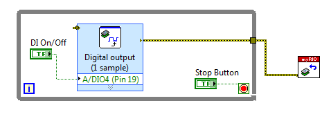
Myrio digital channels always HIGH
When my myRIO is turned, all DIO channels on connectors A and B are in a HIGH, regardless of whether State if I a VI running or not. If I run a simple VI as shown in the figure, the digital status does not change when you click on the button "On / off DI. She is always HIGH. Any idea what's going on?
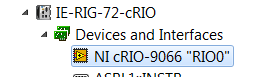
Has it worked before and now it no longer works? I'm sure that you should have the target FPGA called "RIO0" visible under devices and Interfaces in MAX.
This is for my cRIO:
This would mean to me that you are missing a component of driver software - either on your PC (check in the 'software' under 'my computer' for CompactRIO and NOR-RIO and maybe you have installed FPGA module?), or on the target itself (try to reinstall the software recommended on the myRIO).
-
How to run code and to communicate between the computer and myRIO?
Hello
I am trying to create a colortracker using the myRIO. The system is pan tilt servo with a webcam. The project works well and is able to follow and move with the desired color. However, in order to continue the project, I want to ensure the system with another device for the perception of depth and want to use the host computer for webcam and image processing and the myrio to get signals for the servos. The idea is to connect two webcams directly to the computer usb ports and keep the myRIO connected to everything does time i.e. no wifi. Can anyone guide me as to how I would go about sending signals constantly between the computer host and myRIO?
I advise to use Variables shared Network-Published or network stream.
You can read about them both in the cRIO guide Developer: http://www.ni.com/pdf/products/us/fullcriodevguide.pdf
There are also examples for both in the Finder for example LabVIEW.
-
Unable to create an access point to edge MyRIO
Hello!
Today I'm trying to follow this white paper (http://zone.ni.com/reference/en-XX/help/373925B-01/myriohelp/myrio_creating_wireless_networks/) to make my MyRIO Board as access point.
I tried with the Interface of MAX but when I tried to access the network settings on the Board of Directors, he doesn't show me an infinite spinner with writing something like "network card search...". "(Translation of my poor french"search of NIC in progress... »). instead of the menu on the first image at this link http://digital.ni.com/public.nsf/allkb/627507F4737474F286257CB4007984C6.
I said I can't do any operation on the interface wlan0 via SSH (no message such as unknown interface wlan0) and the proxy of my company block access to the web configuration of the network card...
But the main problem is this infinite cone. Why?
Please help guys...
Thank you to everyone.
Afghow.
Hi afghow,
The message "no network adapter found" could be the result of:
-Bad IP configuration.
What is your computer IP address and the cRIO one? (you use DHCP or static?)
-A problem with your firewall
Have you tried disabling your firewall in order to access the parameters of myRIO?
Other reasons can be found on the link below:
MAX error on the system remote cRIO "No. Found network adapter"
Kind regards
-
Hello
Can someone tell me how to access the serial port of the crio 9024. I pass the data to the serial port of the controller. This transmission must be by crio serial port and not by module CSeries.
Thank you
Hello mimran,.
cRIO controllers run LabVIEW Real-time. Therefore, you perform series read/write through the range of NI-VISA in LabVIEW. All data collected from the port, or sent to the port will have to be given "String".
There are examples for reading installed with LabVIEW series. These are only a few small changes to work as in real time.
Follow these steps for an example:
- Launch LabVIEW.
- In the main menu, go to the 'Help'-> 'find examples '.
- In the upper left corner, click on the tab "search".
- Search for the term "series".
- Open the example called "basic series write and Read.vi.
Kind regards
-
Hello world
Having a major problem with my MyRIO currently. I set up a (fairly complex) VI, who until last week worked no problem, made a few minor changes to him these days, which, according to LabVIEW, are very good. The program displays all errors before launch. However, when I connect to the MyRIO to run the VI, it will run for about 3 seconds and then disconnects my MyRIO. No reason is given, and no error log or error message appears to explain why this is happening.
If anyone can shed some light on this situation it would be greatly appreciated
Todd
P.S. attached the VI below, the program has been running for the open loop VI or VI of closed loop
I get that quite often on the cRIO, too. The main cause is that I forgot to include a time delay in a loop somewhere. Sometimes I just too treatment to follow.
The cRIO (and I am sure that the myRIO, too) has an operating system trying to divy time between several tasks. One of these tasks (and probably with the highest priority) is your application. Another task is now in communication with LabView on your computer. If your application does not have enough CPU, communication gets hungry and removes the links.
You can probably see the web page generated by your myRIO, to see what is the CPU usage.
-
Is it possible to have a multiple FPGA cRIO system?
I'm curios if it is possible to have a single cRIO chassis that can be extended with additional FPGA for calculations. Which means, I have more I/O but I algorithms take too much space and need a secondary FPGA to perform parallel processing. Data would be generated in the first FPGA and communicated to the second FPGA where additional processing takes place and then a command/response is returned to the first FPGA which will then be sent through the IO.
I saw something "similar" to that in PXI: http://zone.ni.com/reference/en-XX/help/372831C-01/p2pstreamhelp/p2plv_topo_pipelinefpga/
Although this solution depends directly on the SMU bus there the general feeling for what I want. However, I need this in cRIO. Is there a solution that I missed in my navigation of NI.COM?
It would be OK if the solution uses one of the slots on frame cRIO.
A cRIO chassis only has 1 FPGA on it. You may be able to get an expansion chassis and pass data to it in order to do the treatment. For what you're talking about, you probably want to add a few DIO so that you can directly communicate with the expansion instead of going through the RT chassis and the analytical engine.
You can also get a cRIO with largest FPGA and/or your representative local to la OR the chance to see if you can get some time with a systems engineer OR that can help you optimize your code to fit on a single FPGA.
-
Synchronized analog input and output on myRIO
Hello!
A brilliant new myRIO just landed on my desk and I'm looking forward to learn how to use it.
I have a question about the ability of the default FPGA personality.
Is really similar synchronous HW in and output possible? Can configure you the necessary trigger and clock routing from within VI RT? To say ~100kS/s?
I need to delve into a FPGA design to achieve this?
Thank you!
You will not be able to get your RT loop to run reliably at rates greater than 5 kHz, and we generally do not recommend trying to control I/O faster than 500 to 1000 Hz. This isn't a limitation of the default personality himself, it's just that some tasks are better suited for the OTR and some are better for the FPGA (it is important to understand when developing an application on the myRIO). Synchronization and the output of ~100KS/s signals are something that you have to do on the FPGA.
http://www.NI.com/Tutorial/14532/en/
There are some good tutorials in the link above. They use the cRIO instead of the myRIO but the functionality is basically the same. The biggest difference is that you won't have to add modules to your project, because all the inputs and outputs of the myRIO are fixed and must fill out automatically when you add a FPGA target to your project.
-
Pass a reference to the shared variable
I use two shared variables in a loop where I write one and read each other. I need to repeat this loop 5 times, but each loop uses a different pair of shared variables. These variables are shared between a vi on the computer and a cRio.
It would be ideal to incorporate this loop into a Subvi where I can pass a reference to the two shared variables in and then read and write in threw these references. Then I could just call this Subvi 5 times, instead of copying and pasting the loop 5 times.
Is it possible that I can accomplish this? I can't find an example that would achieve this.
Thank you
If I understand correctly, you can use the mode programmatic access to shared Variables and it would work.
http://zone.NI.com/reference/en-XX/help/371361H-01/lvconcepts/sv_usingdynvarapi/
http://zone.NI.com/reference/en-XX/help/371361G-01/lvconcepts/usingdynvarapi/
-
Deploying the cRIO controller host VI
When I include a Variable Shared Network-Published in my host VI, VI wants to deploy on my cRIO. Without the shared Variable Network-Published, it runs on the host as planned.
Yes, the Sub host VI post work and VI RT is under the lens of the LabVIEW project.
How to use a shared variable in a VI to run on the host computer? I need to pass data between my RT VI running on the cRIO and a host VI running on a Windows host.
Hello Shall12,
I misinterpreted your posts original - this option should be changed to the target on which variables are deployed. Based on your screenshot, the library is contained on the RIO and should be changed it. The behavior you're seeing is described in more detail here:
4TIGNL8A knowledge base: disabling auto-deployment of Scan Engine of e/s Variables
http://digital.NI.com/public.nsf/allkb/D9CF23FD2534E128862575430080CA17?OpenDocument
3V0H36XL knowledge base: connection to a host PC VI in a startup on a real-time target Application
http://digital.NI.com/public.nsf/allkb/A82CEF3FDC14DCA68625712500009649
-
In time real CRIO - writing a file on a PC hard drive
Hi all
I am developing and application with the following hardware features:
Time real cRIO 9004 target device
HAVE cRIO 9205
AO cRIO-9263
and the following programming features:
I run an FPGA VI to establish PID control where the reference signal generated in the FPGA and the real is an acquired signal through the cRIO 9205. I also find target FPGA FIFOs host in order to pass the data from the FPGA to the application of the RT. The time real VI will run in the 9004 cRIO processor. Now, with the data from the FIFO I would write a file (regardless of the extension), in order to do more tests. I did it but I don't want to use the local memory of the RT, instead, there will be a PC (hard drive) where I can place the file in order to write it (with data). I'm not able to do so, as 1) I don't know how to call the PC hard drive and 2) I don't know what communication protocol fits better I want to develop a device to Windows Welcome.
Nobody helps me?
Thank you very much
Enrique
The cRIO-9004 unfortunately has USB, so you can not write on a USB Flash drive (which would be my first suggestion). If you want to store the data on the host PC, you will need to write a simple TCP/IP client/server to send data to the host through TCP so that the host can receive and save to disk. Façade of the VI may seem as it is running on the PC, but it's actually just show you data be listened to the target (you are not allowed to piggy-back on this same Creek).
There are several examples of TCP/IP client/server integrated into LabVIEW.
-Danny
-
OR Scan Engine is available by myRIO or sbRIO?
I see information on NI Scan Engine for cRIO. That exist for myRIO or sbRIO? I can't find this setting when I do a new project. It is a potential project.
Help August 2015: https://zone.ni.com/reference/en-XX/help/373197G-01/target6devicehelp/supported_hardware_rt/
Maybe you are looking for
-
My contacts at e went after iCloud
All my contacts deleted them self from my iPhone which is brand new * happned to them after I made my icloud w? where are they
-
Satellite 1800 400 broken dvd player
Anyone know where I can get parts for my DVD ROM My boy hit a dvd in the player and broke the capture so that it snaps into place. I don't want to buy a new drive as the drive itself is fine. Please help me!
-
Reloaded my xp on an old machine, when trying to update the service packs were saying mistakes along the way. Find a service pack. installed, appears on the screen of the computer, but when try to said updates do install SP2 or I receive errors when
-
Problem software Checksoft home and business
just purchased Checksoft Home and Business and the message I get is: MDAC 2.8 RTM is not compatible with this version of Windows. All of its features are currently part of Windows. I have no idea of what I need to do
-
Smart blackBerry phones ringtones?
So I was finally able to get a good download on the new system. But it seems that now I don't have the ability to choose my ringtones. I went to select, for each email address, and he tells me "Invalid ringtone selected, you must make another selecti