PCI 6221 with BNC-2090 acquisition card
Hello
With regard to connectivity, here is the user manual of the BNC-2090:
http://www.NI.com/PDF/manuals/321183a.PDF
Explanations of the it there all pour a measure differential, CSR or NRSE and how to put the switches pour different modus.
In Chapter 2 it is also the comment explanation connect inputs and outputs signals.
Nice day
Ken
Tags: NI Hardware
Similar Questions
-
Is compatible with BNC-2090 PCI-6723 has?
Hi everyone, I am working in a project where I'm forced to use both a PCI-6723 connected to a BNC-2090 case has... In the datasheet of the 6723 only to versions of the BNC-2110 and 2115 are suggested. Anyone know if I can still use the one I have no problem? I mean, it is, is always compatible 2090, do I have to make some adjustments to the hardware/software, or this is just a desperate mission?
Boards are good, thanks for the help.
Hi Jason
Has BNC-2090 is specifically designed for the X-Series, E-series, M-series and S-series.
The PCI-6723 belongs to the series of analog output and for this reason BNC-2090 has not supported this Commission.The best connection BNC block for this is the 2110. This connection block lists the series of analog output as a series of supported.
Concerning
André Director Napoleao
Application Engineering
National Instruments Brazil -
Using the acquisition card in Labview
I am considering the purchase of an NI PCIe-8242 acquisition card to go with my camera ace acA1300-200uc of Basler. I can't find any documentation on how to actually use the inside of a frame grabber Labview, and I'm very inexperienced with regard to the use of Labview. Anyone has any advice or tips on how I can use the acquisition card?
For reference, I need start a video stream given a trigger to an different Labview vi, then take some pictures and save them to a directory on the computer in the first 30 seconds. I need to keep the video stream up to the end of the trial. But I can't save any video - only a few pictures.
Thanks in advance!
Although he needed the VDM, why would you recommend the duration? He couldn't really use it. It would be wasted money. The only value to it is if you already have an application built using the VDM development software. (which is more than one Service that is more than the card it looks)
If you have no customer Service, certainly grab some cheap acquisition cards. If you already have GOING, I would skip the tips here to blindly buy the card and test your USB3 ports prior to the purchase of surplus material.
As far as how you would work with the BT acquisition card? Really, you won't. You will work with the camera that you plug in LV you won't see anywhere mentioned acquisition card. In MAX, it'll be the camera. In LV, you will use the resource name of MAX. The acquisition card will just be additional USB3 ports.
-
Impossible to test, check, calibrate the card (PCI-6221) DAQ with MAX
Hello
We bought a PCI-6221 DAQ card and we have installed. However, it seems that the device is not recognized. First of all, it appears as a device in the PXI system then that is a PXI system. Then, I don't have access to the 'properties', 'self test' and "to calibrate" menu. This issue should be linked to the first.
I tried to remove the driver and install it again, but it didn't work, so I tried the update but it is the latest version. Is there a problem with the driver?
I checked with Labview if it was possible to use it, but no devices were found by the DAQ assistant. We have the whole NI Developer Suite 2009.
Thank you for your time
Cedric THOMAS
Hello
It works! Great! Thank you very much for your help.
However, does this mean that DAQmx 8.8 is having trouble with the PCI-6221 device? Or I made a mistake during installation (but I have followed the manual)...
I even can I create a simulated device also. That I couldn't do before with MAX 4.5.
Thank you
Cedric
-
How to detect the relay ON / OFF state with PCI 6221 analog input card
In order to test if a relay is ON / OFF using my card PCI 6221 DAQ devices and ports of HAVE it. I conect of the relay contacts to an AO giving 5 v and the other contact to an AI in order to detect the corrent. In addition to a bridge is necessary to close the circuit betweeb the AO and AI.
Shoud this bridge conect the MASS of two ports?
The plan is: relay - AO (5 v) - AO GND - GND AI - AI0 -.
This does not work and gives a continuous corrent to 10 V (I think it is a saturated)
Hint, please?
The simplest connection is:
- One side of the relay contact: + 5V PCI 6221
- Other side of the relay contact: all DI PCI - 6221
But I would add a DI (for example 10 k) resistance to GND of the PCI 6221. This will outline the entrance to GND when the relay contact is open.
-
Need help with counters on PCI-6221 (37-pin)
Hi all
I have a system with a PCIe 1429 connected to a Basler A504 camera and one I use a clock generator (SRS CG635) of 3.9 kHz for trig the image acquisition.
On the same system that I need to add a PCI 6221 37
PIN to acquire:-2 HAVE 39 kHz, synchronized with the acquisition of the image. (Sample of the 10 for each image)
-1 meter to measure a frequency
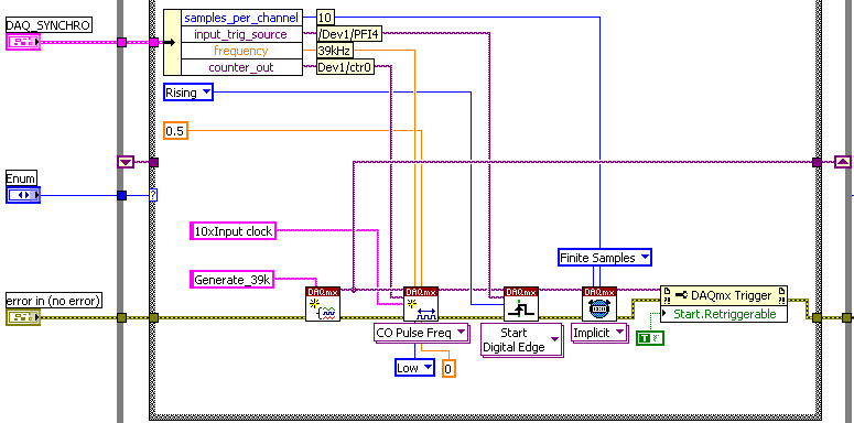
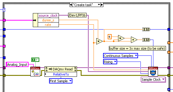
The accuracy of my clock of 3.9 kHz being much higher than what I have on the DAQ card, I thought that an interesting option would be to have a redeclenchables DAQmx task that generates impulses from 10 to 39 kHz for each pulse received from the clock and then use it to trigger the DAQmx AI task.
Of course this can only work if the 'trigger' sources that I defined for these two tasks do not take both counters that I have on the card.
So, let's describe the DAQmx tasks:
-Here is the one who generates the 39 kHz on 0, the counter of the 3.9 kHz I entered as a source on PFI 4 trig
-This is the task of analog input for which I put the trigger on 6 PFI.
It is: I have "softwarely" know the jury to deliver output (Ctr0) 6 FBP counter? And if so, how?
Thanks in advance for any help!
Maybe you missed something that I didn't really point out in my post. The method I described would use the external clock of 3.9 kHz precise as a sample clock, so you would * not * be in danger of loss of synchronization in 1 s per day. You need to only son of this clock signal in a stem of PFI available and configure the task to HAVE it as a result. The 80 + kHz clock that controls conversions within each sample cycle * would * be generated by the jury of 6221, but he don't would not accumulate any out-of-sync error because he gets "retriggered" on each edge of the 3.9 kHz precise clock.
-Kevin P
-
Selection of encoder to use with NI PCI-6221 for a project of inverted pendulum
Hi, I'm a mechanical engineering student is his last years, for my final project I do an inverse pendulum system, the University already offered me this data acquisition card which is a NI PCI-6221, and I have to get the other components (motor continuous, encoders, cables, servoamplificateurs, etc.).
My concern is to choose the right encoder so I have no problem... I was told that the best way to measure the position of the carriage uses an absolute encoder mounted on the motor shaft and some incremental encoders for measurement of angles of clock, but I don't know if the 6221 can handle this kind of data to an absolute encoder, and if so, what are the main parameters for selection? as the format, the number of bits.
In the case where it doesn't work I have to go with the option of incremental encoders for both measure the position of the carriage and the angle of the pendulum, I believe the 6221 can manage entries in quadrature encoders, there´re a lot of examples of this, but since models of incremental encoders are wide enough there´re some features that I worry about : frequency vs the sampling frequency response and the output type.
I found a catalogue which includes two types of digital incremental encoders said their models have 300 KHz frequency response, being the only differences, the output and food, anyway the 6221 can handle this freq resp? sampling rate of the card being 250 kech. / s, would there be any conflict?
They offer two types of output: TTL/74LS04 and line pilot, and even if I go further with the hohner encoders they have the following outputs/freq RESP: RS-422 (TTL compatible) / 300 KHz, push-pull differential/200 KHz, NPN Open Collector/100 KHz and push - pull without complementarity/200 KHz.
Any help would be well received

PD: I don't know if a similar topic has already been posted, I'm again like this... I searched in other posts, but found nothing,
-
Hello
I want to build a program with card PCI 6221 multifunction. In the program, it generates two analog signals to trigger a CCD camera and turn on an LED. Meanwhile, program to acquire an analog signal for a specific duration, and images that are acquired by the camera must be displayed. Above activities in signal acquisition and generation happens to a user the period (the time is currently 1500ms) and the whole process is repeated 40 times. A while-time loop thus serves to launch the signal generation and acquisition and acquisition of streaming images.
Analog signal acquisition should start at a point that specifies the user and he should continue for a set period of time. This is currently done using a digital signal, created and use the port this signal as a trigger of break for AI System. However, all these signals generating and absorbing processors should be well synchronized and accurate at the time. An external clock is shared by all of the clocks used sampling in GOT it, AO and DO (CTR0). Literature, I realized that digital output cannot be triggered in the M-series card, so I use a system of internal release (as shown in the examples in LabView 2010 multi functions).
Question: Is there a good way to start the analog and digital output using another output signal (lets assume a signal generated by CTR1) each cycle in order to maintain a highly synchronized system. (I don't like running the timed loop sample clock and continues to HAVE it and AO).
The 6221 does not have a digital output timing engine, so you cannot trigger directly (or define a.) ReferenceClock, well it's not like that's what you want to do anyway). You can directly use a sample from another source clock, then this clock signal is what needs to be triggered.
I agree with software distribution is not a good idea - you can probably implement this with hardware timing instead, although I don't know how the camera fits into the equation.
I assume you are using CTR0 as an output meter finish, task redeclenchables. Then you use that signal as a sample for AO clock, and I? This is probably what you want to do. Finished Counter tasks require the use of two meters on the boards of the M series: DAQ, so you would not be able to use CTR1 indepdently of CTR 0 if you want to use the outputs of the redeclenchables counter finished. You can always generate 0 if you do not want any voltage output during the acquisition.
Best regards
-
Strange problem with analog output PCI 6251 and BNC-2110
I'm controlling current source of third parties using the connectors of analog output on my card PCI 6251 and BNC-2110.
The current source needs an input signal of 0.1V. I tested it using a battery, the potentiometer and the voltmeter, and by manually adjusting the voltage of power current works - current output with control voltage scales according to the specifications and is relatively stable.
The data acquisition card works too - when I connect a voltmeter to the AO0 AO1, the measured voltage corresponds to the target with great precision value.
But when I connect the current source of third AO0 AO1 data acquisition card, the measured output voltage drops and fluctuates. This applies to both channels of the AO.
I wonder what is the problem here. I suspect it could be a matter of the grounding - the current analog control of the source is an entry with two floating terminals differential. I tried to return the switches FS/GS on the BNC-2110, but that makes no difference.
Anyone knows similar behavior? Does anyone have any suggestions?
-
I use pci-6221, I need her to interface with thermocouple with voltage up to 5v
I use as my pci-6221 or data acquisition card and card 8.2.this labview version gives the constant 10.5 volt signal in at the entrance to analog channel AO on pin 68 and 34. why it shows 10.5 although I did not connect any input.i use type k thermocouple and after signal conditioning with tl0804 I need it interface with AI 0.i channel unaware aware of off the road on the output pins this Card.i need to operate an electric rod that needs 24 volt DC.i give entry to the pins HAVE with variable dc power block after reaching the limit I set(eg:2v) it jumps instantly to 10.5 volts.
You have your task to acquisition of data configured for the mode differential or asymmetric acquisition for the analog input?
I don't understand your comment about to connect the pins WITH a DC power supply. Why is that you connect a DC power supply to the analog input?
Using an analog output or digital output to operate the electric rod? I'll assume that you are looking for on/off control. A digital output is not the voltage or current to drive something that big. You may be able to find a relay for coil 5VDC. Check current requirements. With which you can have the relay to connect or disconnect a power supply of 24 VDC is the actuator. Make sure you have a protection diode across the relay coil wired, so that the magnetic field of the coil does not damage the analog output of your card.
Another possibility is to have the 5 VDC output transistor circuit switches the 24 VDC circuit.
-
Allows you to control two app PCIe-1427 acquisition card program?
Is it possible that NEITHER MAX poster image and a program of Uart control a camera through PCIe-1427?
I'm designing on a FPGA board with a link to the camera, and the side FPGA generates the image of the target. and PCIe-1427 Council receives the image.
I'm contrling the map via USB2UART FPGA, and MAX displays the image. This works.
but instead of USB2UART, using UART is possible with the terminal program such as putty and teraterm via PCIe-1427?
In fact, I can't because teraterm cannot see the PCIe-1427 uart port. However neither offers
device driver, I think it would work.
If there is the driver that shows the interface UART to PCIe - 1427 as normal COM port, where is it?
If this is not the case, why is that this driver?
And there at - it can access any other OR acquisition card that provides the link camera and COM port interface the other terminal program series?
Thank you..
Imperx software automatically find the port (I use Imperx camera).
When the farmed grabber is installed and NEITHER-IMAQ is installed the software should automatically find the camera.
Have you tried running the capture with Standard camera card? I understand that you create something special on FPGA.
-
How to find the time between two channels of entry in the data acquisition card or pci 6036
Hello
I read a lot-related posts on the simultaneous measurement of two input voltage of similar channels in map data acquisition. I know that the best material is "simultaneous measurments of the Series DAQ cards" but I only pci data acquisition card 6036 and I try to understand what is the time between the reading of the two channels . This period is always constant? (must it rely on a voltage (amplitude, frequency, waveform..). I send the sine wave (s) to the two channels and read the values of V, if they read the same value, the difference should always be zero but I get-0,002 to 0.002 Volt difference (I must find a way to convert it in time). A screenshot of my VI is attached. I wonder how I can accurately measure the time delay between the channel.
I am open to any suggestion, my final goal to read exactly two channels at the same time ((ou connaître le délai exact donc je peux correspondre les données correspondantes étant donné le temps de retard))
Hi spinup,
better you should post your question in the forum of LabVIEW, LabWindows/CVI is used

Good luck.
-
I need to generate 3.3 V logic level Digital train of pulses with the NI PCI-6221. Can I change the level of 6221 OR logic output?
The output cannot be changed. 5V to 3, 3V level controllers are readily available (Maxim, I think). As long as the scanning speed (etc.) is fast enough for your pulse train, even 3, 3V regulator would work. I don't know if NEITHER offers a module to condition TTL levels.
-
Exposure / white - black voltage settings on the PCI-1410 acquisition card
Hello
I use a PCI-1410 acquisition card and have written acquisition software in Visual Basic .NET.
In measurment studio there is a button that automatically sets the tensions black and white, based on the tensions of entry on the channel.
I want this impliment into my VB.NET code. I am aware of the 'CWIMAQ. BlackReferenceVolt "and"CWIMAQ. " WhiteReferenceVolt' properietes, BUT is there something that will automatically adjust the tensions? I ask because I don't have background no function that will probe to find what is the maximum and minimum voltage that is nessasary to dynamically set the tensions.
Thank you
Jonathan
Through the research forum. If the solution below to create the IMAQVision control. IM assuming that the reason why it wasn't available is because I do not have the license of installed vision
Dim IMAQVision As New NationalInstruments.CWIMAQControls.AxCWIMAQVision
IMAQVision.CreateControl) -
What is the acquisition card OR 1426 compatible with a line/Linear array scanner?
What is the acquisition card OR 1426 compatible with a line/Linear array scanner?
I'm currently doing a feasibility study of the project that uses the NI 1426 and a linear Array Scanner acquisition card, and I would like to know if they are compatible with each other.
Thanks in advance
Martin
Hi sandeepchinni,
I agree with gunnesjr that we need more information about what you mean by Linear Array Scanner. As he said if it is a scan line or an area then yes it will most likely compatible. A small correction to what he says. You need not buy NI Vision if all you need to do is to acquire images. The framegrabber will be delivered with the software that is needed to work. If you need to do any image processing then you need NI Vision. The following knowledge base lists what is installed with the driver for the card. Live that are installed with OR-IMAQ Vision Acquisition Software?
Maybe you are looking for
-
Mac OS 9.2 mouse blocked thoroughly after installing USB Overdrive
After you restart the installation of USB Overdrive, my cursor is stuck at the bottom. I can still move it horizontally, but not vertically. I can't restart in OS X 10.4 to uninstall USB Overdrive, because I need the cursor for this. And since they a
-
After updating Firefox. Tabs not saving
Hello.After Firefox, upgrade to 37.0.1. Tabs not save after you close the browser.I re - install Firefox. Problem not solved.You can correct?
-
Hi, I'm trying to customize some controls, but I have a problem with the construction of a button. I replaced the central image by a more realistic appearance and now I want to change the scale to better understand my button again, but I can't put ac
-
I try to open with a pdf file, and it says I have to update the windows photo gallery, but it will not be updated.
-
Bluetooth headset does not appear in the control panel
I try to use my bluetooth headset. It is paired with success and it seems in the window bluetooth devices. However, it will not work. I looked in the sound control panel and the helmet does not appear. This use to work, but stopped. How do I add