PCI-6251 vs PCIe-6351
Hi all
In another thread here somehwere I spoke getting the smaller possible buffers to reduce latency when reading and writing to the acquisition of card data in a loop. The "10% rule" came (i.e. setting the buffer size of e/s to 10% of the sampling rate of 100ms per buffer) and although it seems to work on most systems, on some systems, well I can do much better than this, reliable: I can do full Visual Studio 2010 then builds in this loop , using a few sizes of buffers of 20ms, without a single negative overflow error. It's all about a card PCI-6251.
I decided to see if I could do better with a PCIe-6351 surfboard, hoping all latency issues could be mitigated by the PCI express bus. Unfortunately, things are much worse. On the same system where using 20ms puts in buffer (at 100 kHz sampling) was the test of the bullets; for example I couldn't fail any load I put on the CPU (a quad core Xeon hyperthreading), using the same code with the PCIe-6351 could not even past the start of my loop of I/O without meeting many overflow errors. I increased the sizes of buffer to 100ms (as recommended by the basic rule), but still have occasional overflow errors, even with virtually no load on the PC.
Another question, I noticed during the transition to the 6351 that surprised me was synchronization; another application considerably depends on the sync input and output buffers. It worked well on the 6251, taking into account delays caused by the buffering. The same code fails on the 6351; not with a code error, but tampons are not synchronized. I did a thorough analysis of this yet (I put emphasis on the first problem above), but it seems that the IO can be synchronized by a partial buffer; in any case, the behavior is quite different, questioning reports cards of the same physical buffer size in each case, using DAQmxGetBufOutputOnbrdBufSize.
I'm not sure what my question is, except, "huh?" The biggest difference that I could find on the sheets, is that the 6351 has several DMA channels, which could only help (although I don't think I need more than what's on the 6251). If someone could shed some light on that, I'm all ears.
(It was all done using the 9.3.5 drivers supplied with the PCIe-6351;) I don't have the time to go through the pain and suffering that is updated to the NOR-DAQ drivers yet - my company has limited bandwidth and, let's face it, 1.3 GB for a simple driver update is ridiculous, not to mention the time it takes actually install.)
Hi, JSA,.
Take a look at your other thread, my first suggestion is to disable the regeneration on your output task. In c#, use the following text:
myTask.Stream.WriteRegenerationMode = WriteRegenerationMode.DoNotAllowRegeneration;
WARNING 200015 can only come when you use regeneration, and it occurs when you copy data on the same portion in the output buffer that the device is being read. It does not necessarily indicate that an overflow would occur with disabled regeneration. If you have enabled the regeneration (which is the default) then the unit will try to keep its edge FIFO (8191 samples) filled with data that is currently in the output buffer, so you could get the additional data transferred to the device before you have a chance to replace the previous buffer.
In addition, you mentioned that "i/o can be out of sync by a partial buffer." While I don't have too much to go here, I wouldn't be surprised if regeneration disabling fixed this problem as well. If you transfer a partial buffer of data to the device, and then write the new data, your output waveform may appear out of sync with where you expected it to be. It is best to simply disable the regeneration, in which case the output buffer is treated as a FIFO, and not a circular buffer, so you're never more than expected.
Once you disable the regeneration, you will no longer receive WARNING 200015 and I believe that potentially you will not see the synchronization problem. If the loop of Scripture cannot meet the generation, you will now see 200290 error, which is a mistake of underflow true (i.e. no data is present in the FIFO shipped on time the sample clock is received). If you encounter some errors-200290 rates and sizes of memory buffer that you think are unreasonable, please do after return and I will be happy to take a look at your code to see if what you see is logical.
Best regards
Tags: NI Hardware
Similar Questions
-
Timestamp of the external Signal triggered using the PCIe-6351
Hello
I use a PCIe-6351 to acquire externally triggered data. My block diagram looks almost exactly at this link in the section A. Posttriggered Acquisition with a digital start triggering:
http://www.NI.com/white-paper/4329/en
As you can see he is a straightforward acquisition. My trigger signal is on PFI0 and it is supposed to occur at regular intervals. However, I started to suspect that it varies in time. For example, if this is supposed to happen every 2 milliseconds it can range from 1.9 to 2.1 milliseconds. Is it possible for DAQmx record the time at which each trigger occurs? I realize that it will not be synchronized with the time on the PC, but as long as I can have a time stamp of each trigger I can subtract each time individual time of the first condition for the time between triggers.
Thank you!
Steve
MR. O,.
Thanks for the reply. My system is set up to acquire many points of data at a relatively fast pace, so I their stamp on the data acquisition card and only download on the PC once the acquisition is completed. My understanding is that writing to file measure vi set a timestamp whenever he writes to the file - not for each individual data point. Is this correct?
Steve
-
Encoder 6351 PCIe and quadrature + voltage sensor.
Hello! All the experts,
I am considering 6351 PCIe to use as a counter and all of catch data.
The question is how to use the input channels equipped with PCIe-6351 quadrature encoder and correspond to voltage sensor data.
1.
Ex)
Each quadrature encoder pulse count, take each value of the voltage with the value counted (Crank angle)
Rising edge of a pulse of 1 2 3 4 5 6 7 8 9 10 11 12 13
Value of sensor vol. 0.1 0.6 0.8 1.2 1.5 1.9 2.1 2.4 2.8 3.0 4.0 4.2 3.5
I would like to know how to get the data using 6351 PCIe quad. function...
2. in addition,.
Do you know how to directly transfer the values of the voltage sensor of PCIe 6351 VI FPGA?
Ex)
Value of sensor vol. ===> PCIe-6351 ===> VI FPGA (analog channel in FPGA)
Could you give some advice?
All tips are welcome!
Thank you very much!
Best regards
Hyo
Hi Hyo,
To the best of my knowledge, the PCIe-6351 isn't any FPGAs; FPGA is generally available on the platform of RIO and R series cards. As such, I'm a little confused by what you mean when you say that you want to transfer the values of voltage for the FPGA VI.
If you use our API of DAQmx LabVIEW, you can use redeclenchables Analog Input to collect a finite quantity of samples of your card for the acquisition of data each time a trigger (e.g. a pulse encoder) is received. This article has a bit more information:
http://digital.NI.com/public.nsf/allkb/14843A49037D7E368625769C006F7A65?OpenDocument
I hope this helps!
-
Hello again everyone.
I looked through the other posts and have tried all suggested without a bit of luck. (other that a complete uninstall, re - install)
I'm forced by my Department to upgrade systems to Windows 7 64-bit and a computer Lenovo ThinkCentre shinny new M series.
My problem is with MAX v5.0. I have a PCIe-6351 and a PCI-6052E installed in the system, windows recognizes the card and according to the Device Manager, everything works fine. The problem is that devices are not appear in MAX under the tree of devices and Interfaces. I'm refreshing the tree and it is said, it is looking, but he never finds anything. I used the tools > Reset Configuration option and have nothing done.
Could there be a security features that are installed that may stop MAX from the voting systems hardware correctly? Only, I only ask because I was told that some hard enough security practices will be implemented with the new computers, I am about to receive.
I gained administrative rights and run MAX under an administrator account, but still no luck.
This is a new installation and I received no errors, everything seemed to install correctly.
Any ideas how to solve this problem?
Your help is as always, very much appreciated.
Steven M.
Well, my problem is solved. MAX recognizes all my devices and everything works as it should. The solution is a bit anti-climatic

The source of the problem was that NEITHER System Web Server (NiApplicationWebServer) service did not, who stopped the mDNS responder service of the race, which, in turn, stopped the service of charger OR to run.
Try to manually start the MSDN OR system Web Server & National Instruments that service would result in an error 1075, you try to start the device loader neither resulted an error 1068.
My Department of systems had no ideas on what safety measures or protection of viruses on their end parameters might be the cause of the problem.
Solution:
Control Panel > programs > programs and features > National Instruments software > uninstall / change > measure Automation & Explorer > repair.
After the repair, everything works fine, and all of the above services are running.
The installation process has shown without errors or problems, so I am at a loss as to why he needed repair. But whatever it is, problem solved.

-
NOR dear Experts:
I use NEITHER-DAQmx ANSI C to develop software to acquire an analog signal by PCIe-6351. The sample clock is generated internally, which will be sent to trigger a transducer. The sample clock rate is about 4 Hz. I'll acuqire believes over data on each digital trigger, which is redeclenchables. The snippet of code like this:
DAQmxCreateTask("",&taskHandle);
DAQmxCreateAIVoltageChan(taskHandle,"Dev1/ai0","",DAQmx_Val_Cfg_Default,-10.0,10.0,DAQmx_Val_Volts,NULL);
DAQmxCfgSampClkTiming(taskHandle,"",10000.0,DAQmx_Val_Rising,DAQmx_Val_FiniteSamps,1000);
DAQmxCfgDigEdgeStartTrig(taskHandle,"/Dev1/PFI0",DAQmx_Val_Rising);
DAQmxSetStartTrigRetriggerable(taskHandle,1);DAQmxRegisterEveryNSamplesEvent(taskHandle,DAQmx_Val_Acquired_Into_Buffer,1000,0,EveryNCallback,);
However, I need to save data from RS232 to each trigger starts exactly who needs to synchronize with the recording of the analog signal.
So my question is how can I get each startup trigger event or recall or read the timestamp of each trigger early?
Thank you very much.
Hello
Below I've linked to a Knowledge Base that will give you a few options to get a timestamp in a C environment.
http://digital.NI.com/public.nsf/allkb/354468202721D85D8625759F004B0357
-Jake B.
-
Duration of the individual sample - OR-6220 and NOR-6723
Hello
We are acquiring data through NOR-6220 and NOR-6723 Renault in our laboratory. The data acquisition process through Data Acquisition Toolbox of Matlab, where we put the sampling rate of the analog inputs to 10 kHz - or 0.1 sec per sample. Now, we wonder what is the time of the sampling process, i.e. the period during which an individual sample. Is there an average process for the duration of the sample (0.1 s), or during a window much shorter? In the latter case, how would know us the exact duration, and it would be possible to control it?
In our case, we see resistance jumps in our system. Even if we get a range of resistances, we suspect that these jumps can actually be between two distinct levels; It is possible that the process of averaging during the sampling results in obtaining intermediate values between these resistances. Have a shorter window of sampling would be useful in addition to interpreting the results.
It seems that this could be a trivial question, or who might be a Matlab thing rather than a thing of the card. Bear with us in these cases; We have made an effort to research on the problems on the forums and elsewhere
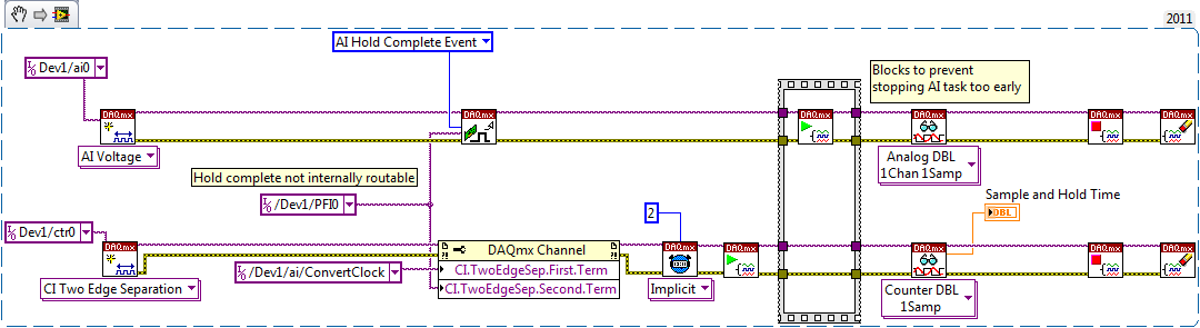
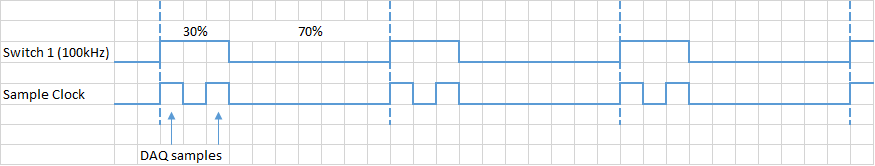
. Thank you!There is a sample circuit and hold on the device. The clock to convert marks the beginning of the sample interval, while the complete signal of cale HAVE mark the end.
I don't know if the waiting time is nowhere specified, but you should be able to measure like this (example LabVIEW... I don't have MATLAB or the Data Acquisition Toolbox unfortunately):
On my PCIe-6351, I get a waiting time between 440 and 450 ns. The 6220 can be different, but I hope that gives you an estimate. This setting is not adjustable.
Having said all that I don't think it's relevant to your question. If your input signal varies between different levels and you want to try that once it has established a new value, you must ensure that the task of IT is synchronized to what generates the signal.
Best regards
-
Measure the intensity of the flash using a photodiode
Hello world
I want to measure the intensity of the flash of my flash lamp using a photodiode.
Maximum repeat of the lamp flash rate is 500 Hz, the duration of the pulse ~ 2 µs.
Right now I use a card counters/timers PCI-6602, so I have to buy new material (max $ 2000) in any case.
The precision should be as high as possible because the signal is used to normalize the flash fluctuations in my measurement.
I don't know what hardware meets my needs (USB-6009, NI PCIe-6351,...) because there are so many options.
Any recommendations?
Thank you!
Johannes
Johannes,
Yes. Additional information has been very useful.
1. you can consider a tube set, as opposed to a photodiode. Who spends the majority of your budget here rather than on the acquisition daq hardware but can give you better optical performance. PMT can be very sensitive (responses of single photon), fast and low noise.
2 and 3. For an area under the curve as, I would consider a high speed Integrator (OPAMP fast with return of capacitor). The output is a voltage proportional to the area under the curve. Because you must read at 500 Hz, a relatively slow and cheaper DAQ hardware could be used. You must also reset the Integrator after each reading.
Consider the comparison between direct scanning of the curves in your image to the Integrator, I proposed:
A digitizer to 10 MHz capture 3 or 4 samples non-zero on the closer peaks and probably no sample in the upper part of the pulse. Thus, the calculated surface might have significant errors. Certainly greater than your target < 0.1%.="" faster="" digitizers="" with=""> = 12 bits of resolution (required for accuracy) are very expensive.
Op amp Integrator costs ~ 10 US $. The other required components that would increase slightly. Even if you were to buy a power supply and an enclosure for the Integrator, the cost could be< $200-300="" us.="" the="" sampling="" rate="" of="" the="" a/d="" conversion="" is="" ~="" 500="" hz.="" ="" even="" a="" usb-6008=""><$200 us)="" is="" fast="" enough,="" although="" its="" triggering="" and="" accuracy="" may="" not="" be="" good="" enough="" for="" your="" application.="" certainly="" there="" are="" several="" devices="" in="" the="">< $1000="" us="" range="" which="" are="" more="" than="">
4. stay with the 6602 for measurements of frequency and generation of calendar. It works well, has an impressive track record and you already have it. Add the input device a adapted analog and you should be ready.
I don't want to make this sound too simplistic, because it isn't. What you're trying to measure requires some effort and a few precautions to ensure that you get significant results. For example the discharge that powers the lamp flash can produce powerful electrical transient signals. These could be much larger than the photodiode/PMT outputs and they occur simultaneously. Preventing transient corrupt measures may require a substantial amount of test and design.
Lynn
-
Entered analog PCI 6251 not extent of tension of a mass flow controller
Hey,.
I have a data PCI 6251 M acquisition with a break in Council SCXI 1302.
I'm trying to measure a 0 - 5v analogue output voltage from a mass flow controller (check picture of PIN)
When I measured with a digital multimeter the voltage of the flow signal (PIN2) and common signal (PIN12) I get a stable right tension between 0 and 5v depending on the flow set up. I can control the amount of the charge by providing a data output set point PIN8 and common PIN12 of the 0 - 5V analog signal.
Now when I connect the signal flow PIN2 and on my DAQ signal common PIN12 AI and AIGND, I don't get readings on my labview VI of the AI. In addition the flow does not meet the setpoint voltage, it get stuck in a range of values no matter how I vary the OD 0 - 5V of data acquisition in setpoint PIN8 and PIN12 common signals.
I have to add that I tried different ports HAVE with results of sam, and I also tried to measure my supply voltage with my HAVE and all the good work.
It seems that the entry of AI affects the AO output voltages to my charge. What would cause this? That would be a problem of impedance adaptation?
Management or ideas are appreciated.
Thank you
Ali T.
Update for anyone that might interest you:
I not connected to the ground of the power of the mass of the signal of FJA FJA.
Once I did the acquisition of data reads all data as expected.
So it turns out not to be a problem of acquisition of data, OR at all, but a game of question for my part, as I suspect is the case with most of the problems.
Jeff Merci for your comments.
Ali T.
-
Error 200452 with break triggered DI on PCI-6251
Hey guys,.
I am writing a program to snoop on SPI communication between a microcontroller and two MAX-7221 display drivers. Essentially, I want to read the PIN Din of both fleas and convert the data stream in the numbers that are displayed on the front panel of devices (each chip controls two 3 figures, 6 total). The data is 16-bit and contains a 4-bit address and a 4-bit code representing the number b. I recognize these two values in the vi, convert code B in decimal and use the address to combine each digit in the corresponding 3-digit numbers that I can view and save to a file.
Each chip has a Din row that contains data, a clock and a load signal (called CS). In my vi I acquire the data using the remote clock signal and use a trigger break to acquire only when CS is low. It worked perfectly to collect data of a single chip MAX-7221, but I started to run into problems when you try to acquire data of these two channels at the same time.
Since I am on two different trigger and clock signals, I couldn't use a single data acquisition. I got a PCI-6251 card laying around and decided to use it to develop a single chip and my original USB-6361 to acquire the other. Acquisition data from as chips with the USB-6361 works perfectly, but when I try to acquire two Renault at the same time I get error 200452 associated with the trigger break PCI-6251.
I did a ton of digging, but I can't seem to understand what the problem is. The Web site OR said that the PCI-6251 supports triggering of break, and any channel I use, I still get the same error. I even tried to use other types of triggers, but no matter what I do error 200452.
Thoughts?
Thanks in advance!
Colin
It seems that the PCI-6251 card only supports digital break triggering on a similar task. You use it on a digital input task. 6361 USB supports triggering of break on the two types of tasks. That's why you get an error.
-
How to generate two pulses per cycle? PCI-6251/6255
Hello. I want to generate two or more pulses per cycle like the timming diagram. This pulse will be used to trigger the sampling data.
I am ussing the PCI-6251. The VI examples to counter outputs can easily generate the first line, but the second I have no idea. All information can help.
Another problem could be the synchronization of this lines and data acquisition.
Concerning
Ivan C.
I would like to use the digital outputs for this - just generate a continuous at 1 MHz clock using one of the counters and write the following in your digital output lines:
H H H L L L L L L L
H L H L L L L L L L
If you want to use these signals to pick a different spot on the 625 x, you the output of wire in a PFI lines.
Best regards
-
connect labveiw 8.2 with nor pci-6251
I have no pci-6251 and its cd driver with labview 8. How can I connect the daq with labview 8.2 and run programs
Hello
I can't download the driver of NOR-DAQmx 8.7.1, connect labview 8.2 with NOR-DAQmx PCI-6251...
Why?
Please answer...
-
How to read digital signals with pre-and post-trigger on a card PCI-6251
I have 22-bit parallel position of data entering TTL lines to 16 kHz with a pulse of marker that says when the data is valid. I also have a fault line which gives an impulse when an error condition is met. I want to read in the 22 lines of position with 500 positions of pre-event and post-event 500 data when the fault line says. How do I pre and post-déclencher lines digital input on a card PCI-6251?
If this is not possible on this map, which maps PCI would be possible?
-
Blocking of blue screen with the analog voltage (WinXP, PCI-6251)
Hello
I'm looking to solve a problem of blue screen with my measure blocking
application, which I am developing with C++. Blocking seems manifest
a little random after a variable amount (500-50 000) of voltage analog
measures. My application needs to make a huge amount of these digitally
trigger voltage measures after a certain period of time, and I'm using a
unique
task to do. The task is stopped and started after a single measure
is
which is done around 10 000 - 100 000 times per second. For this
because I do synchronized with the PCI-6251 map data acquisition and
one
Ztec oscilloscope card. It seems that the probability of blocking could be
associated with
the frequency of measurements of voltage that I perform.The
the app itself is multithreaded, but I'm blocking concurrent access
TO
the card with lock - all access to the card are behind a single mutexlock, so simultaneous access is blocked. In any case, all data acquisition
access
o the map is initially a single thread, which is dedicated to the acquisition of data
operations.I also did stress tests with Ztec scope map, which does not
result
in all the problems. I also disabled in order of acquisition of Ztec map data
TO
Make sure that it wasn't the card scope, the origin of the problems - the problem
persistent, so this seems to point towards the direction of the nidaq map.The deadlock appeared when I used the original supplied with drivers
the
card. I installed the latest drivers (removed the device from)
' Windows
Device Manager and your application Measurement & Automation, reinstalled), but the blue screen still appears.Blue screen gives me a few debug data, but it does not mention any
files .dll or something that would be of course point to a specific file (driver). I enclose at least partially matching code snippets.
Hello again! I've been in contact with a local support person, who suggested that I have use DAQmx_Val_FiniteSamps instead of DAQmx_Val_HWTimedSinglePoint. I don't have any other changes, but this (see below) and the problem disappeared, so this seems to be an acceptable solution, because I don't see at all why not do this way. (Thanks Henry!)
DAQmxErrChk (DAQmxCfgSampClkTiming (task_reader, NULL, 100000.0, DAQmx_Val_Rising, DAQmx_Val_HWTimedSinglePoint, 1));
DAQmxErrChk (DAQmxCfgSampClkTiming (task_reader, NULL, 100000.0, DAQmx_Val_Rising, DAQmx_Val_FiniteSamps, 2)); -
Outbreak of similar PCI-6251 reference edge does not work with two channels?
I use this card PCI-6251 to acquire data from two channles of entry. I need to use reference similar edge trigger. the trigger for the chan signal 1 and acquire data from chan 1 and 2 chan. However, the error is that this card can't take two channels with similar trigger edge reference. Please check if it's the PCI-6251 limilation. If so, can you suggest any other card can do this work? The normal extent can trigger from one channel and acquire data from many other channels.
Thank you
Liming
-
Analog triggering on PCIe-6251 using BNC-2120 on Mac Pro?
Hello all-
There, does anyone know how an analog trigger using a PCIe-6251 card connected to a box of BNC-2120 interface? I am running LabVIEW 8.6 on a Mac Pro OS 10.5.6 and my VI of analog data acquisition seems to work but hangs up waiting for a trigger. The trigger analog signal must be applied to the terminal APFI0 and the BNC-2120 contains no connector with this name. On the M-series cards, APFI0 corresponds to pin 20 on the map itself, but I was not to locate any information that shows how the pins of the connector BNC-2120 connect internally to different spring on its façade and BNC connectors. Sales people NOR recommended the BNC-2120 as the correct one to use with the PCIe-6251, interface box so I think that probably one of the many connectors on the front panel of the box is wired to pin 20. Am I wrong? I spent hours to connect signals to the box in the hope of getting a trigger, and nothing has worked yet. To make matters worse, reviewing the VI to trigger a data acquisition using a TTL signal connected to all of the PFI 0... 9 connectors on the BNC-2120 just causes of VI to give undefined error message ' specific 89136 route cannot be met because the hardware does not support it.» The specifications for the PCIe-6251 indicate that a digital trigger should be possible through the PFI connectors, so it's a puzzle. I have an interface BNC-2110 box in the case which turns out be a solution, nothing about it is named APFI0 either. Any suggestion would be of interest. Thank you.
-Ken1
Hi Ken,
Unfortunately, the BNC-2120 doesn't have a connection available on the APFI your M series line. The BNC-2110 has this connection available.
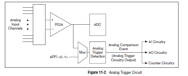
A possible workaround is that you can trigger off channels of analog inputs as well. Here is a screenshot of the M Series User Manual that shows the analog switch-off circuits:
There are a few caveats to trigger off AI channels (mentioned in Chapter 11 of the manual)
If you use a trigger to start, the analog channel that will be triggered off the coast of must be the first string in your scan list.
If you use an analog input as a reference or a relaxing break, it must be the only channel in the scan list.
I hope this helps!
Best regards
John
Maybe you are looking for
-
Adobe Flash does not work with mozilla, works will be all other why e/s?
A recent update had left my computer do not leave Fire Fox on the internet, so I uninstalled and reinstalled and found out then that I had to re add it to the firewall, because he could not work. Then, when I went on she worked and loaded fine, but n
-
HP 17bII +: yield to MATURITY of bonds
Hello! I'm trying to calculate a yield to MATURITY of bonds. Liaison for £110.5 trades, has a coupon of 9%, that has just been paid and the next payment will be in exactly one year. The binding is exactly five years to maturity (at £100). How can I u
-
Create a shortcut through the program?
Hello Is it possible to create a shortcut to my program when a user clicks a button? I thought to copy and paste a static shortcut, but the target of the shortcut must includes a file that specifies the user. Is it possible to do?
-
HP 6700 JO scan to computer, what must be the digitized file?
Scanned several pages using printer HP 6700 commands and scanned on my computer. Unfortunately, he failed to tell me where the hell the files went? Knew I should have stuck with scanning the computer and not the printer.
-
Windows Server R2 2012 unexpected restart
Hi guys,. I have a problem with one of my DELL servers running Windows Server 2012 R2 Std. It is a new Server Power Edge R630. The problem is that it has restarted unexpectedly by itself. So far, it has happened twice. I raised this issue to DELL tec