PCI6120-acquire an analogue signal on each edge of a digital signal
Hello
I have the card PCI-6120 and Labview 7.1.
I have a digital signal of the encoder. Am interested in buying an analog voltage on each rising edge of the digital signal. In addition, I have another digital signal (index) between which I wish to make the acquisition.
I tried several options. But I can't get on the digital dashboard via the hardware. Please help urgently. Alternative, I migrated to the acquisitions acquisition high speed analog and two digital channels and deteting change in software programming and then find the analog voltage. Which is heavy and inefficient.
Kindly guide correct programming technique.
Concerning
Marie-Hélène
Hi, Maud.
Thanks for the update and I hope that your well today.
Sorry for the delay but it was the Easter holidays!
Thank you for your congratulations.
I put your sampling frequency at the maximum rate of the clock source (encoder). The DAQmx driver uses the sampling frequency (and the number of samples per channel) information to perform various calculations and set sizes for the buffer.
If you set it too high, nothing will happen-guests still just on each edge of the unit receive. If you set it too low, your stamp could be too small and you may lose data.
Hope this helps,
Tags: NI Hardware
Similar Questions
-
Visual control of an analogue Signal, varying in time
Hello
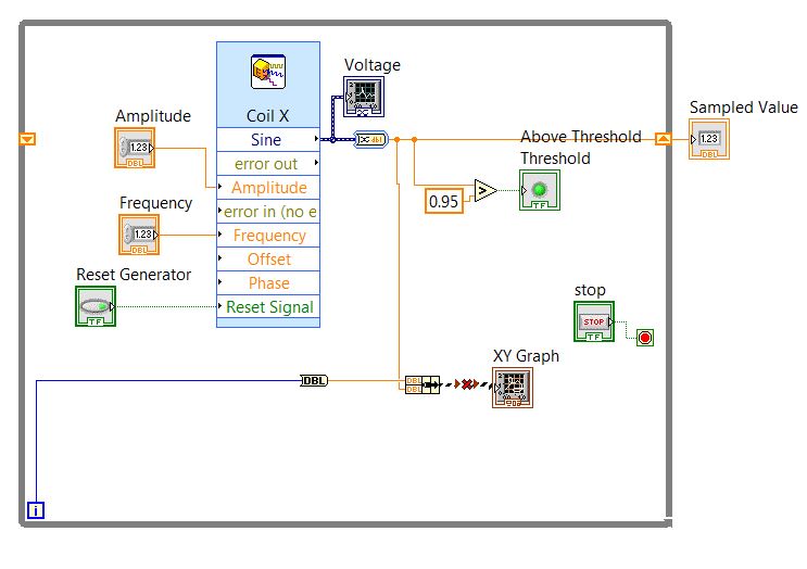
Here is my configuration (Fig. 1), where X coil - block "simulate Signal", which emulates an analog value that varies in some way.
This value is the result of a treatment on analog inputs... in this configuration the signal, I chose wave SIN just for simplicity.
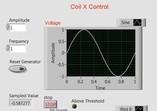
Is it possible to view the evolution of this signal in time... I mean that the "time window" on "Voltage" graph should move forward (Fig. 2).
I tried to use XY graph rather applaying (Figure 1, bottom of th), the iteration count in the loop 'While' for 'Time '.
but received an error message: "you have connected 2 terminals of different types.
What could be a solution (of course if I want it is feasible)
Thanks in advance
Pavel
Fig. 1
Fig. 2
Hi Pavel,
you don't 'manage' the history of a graphics buffer, you pay at the time of publishing. At runtime, it is fixed!
There is no difference between the periodic signals and not periodicals: you measure with a certain frequency of sampling and you decide Samper how useful are stored in the buffer. Point.
When you want to have a variable buffer (or: variable x scale) you must buffer on your own and use a graphic instead. So we're back to your original question: context-sensitive help will show you the data types expected for graphics, when you hover over their terminals!
-
How to acquire the generated signal?
Ladies and gentlemen, I am a novice in LabVIEW even if I practice solving problems more or less difficult, I got NOR cDAQ-9178, possess an entrance connected with output channels and after a plan of work on the signal acquisition and production separately, I decided that I could successfully combine the two plans and get the system of acquisition of generators. Hell I didn't know it wouldn't work. There are probably many things im doing wrong in this case, so no finance or support directly with the .vi is attached to the message would be so appreciated. Thank you.
One thing I think is that your generated frequency is not suitable with #S and Fs you have configured. Try #S = 10 k and Fs = 100 k.
-
Frequency of an analogue signal measurement and noise reduction
Hello everyone.
I'm reading a flow rate sensor that generates output signal square whose frequency has a linear relationship with the flow rate and varies from 37 to 550 Hz. My hardware does not support playback of the frequency, so I have to calculate. What I ended up doing was reading signal every 1 millisecond (1000 Hz), taking two samples spread and store the value of the signal and the time during which it was read. Every 400 milliseconds, I loop over the data and know how many cycles have taken place and the time between the first and the last cycle, divide the number of cycles at this time here.
Here's a graph of the signal.

I never use software loops timed then performing operations of data acquisition as a general rule. He's many trendy on negative issues. And as you mentioned that you cannot run a timed loop faster than 1 kHz. You should go to the Help menu in the toolbar, then select search examples. Then you look up "continuous acq. It is best to leave all the details of the calendar to the data acquisition unit and just retrieve data from the buffer of data acquisition, then it is needed. I have your case I would recommend a sample equal to 6 kHz freq. That's more than 10 times your highest frequency. You can always update your data at intervals to 400msec. Your signal also looks good. I can't have a lot of noise in your signal. If my guess is that your software is not optimal. You should not get 120 Hz, so there is no flow. If you post we can take a look.
-
ThinkPad Edge E520, paved digital / numbers issues
5, 4, 2, 1, 0 and enter digital button on the digital pad Lenovo itself works only half the time (sometimes it works, sometimes it doesn't).
When I use an external keyboard, there are no problems.
I just got this computer about 2 weeks ago too.
@FrankyG,
Check out this clip. E420 and E520 has the same built.
http://www.lenovoservicetraining.com/ion/E420/
Manual of Maintenance of equipment for E520.
http://www-307.IBM.com/PC/support/site.WSS/document.do?sitestyle=Lenovo&lndocid=MIGR-77264
JMT
-
Acquire 2 digital signal of custom scale (Engg units)
I am a newbie to the world of DIO.
I write a VI to acquire 2 digital signals. one of a load cell and others for engine rpm (legumes). I need acquire these two signals and then convert them to engg units using the custom scale and write it in a txt file with timestamp.
Please suggest the best ways to accomplish this task.
Thank you
DAQG
Look at the examples on DAQmx in the finder of the example.
You would not really acquire 2 digital signals. You would acquire an analog signal of the load cell. A digital acquisition or against, this is what would make you the acquisition of the motor. Looking for analog and the counter measures in the finder of the example. Some of the example should show you how to apply the custom scale.
-
Analog output with counter Falling Edge
Hi all
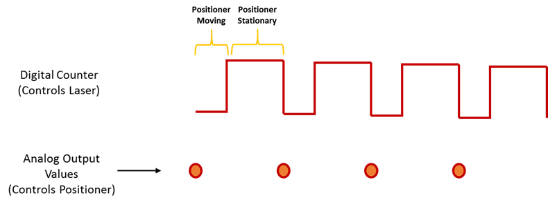
Here's the iamge which describes what wishes to accomplish. I would like to trigger that the AO output with the edge of the fall of the meter.
I have set the clock for my AO as the counter.
The analogue output should be raised whenever the Digital signal meter falls
SAMPLE_SIZE = 80
SAMPLING_RATE = 40 #Samples are written every 25 milliseconds
TIME = float ((SAMPLE_SIZE) / (SAMPLING_RATE))CREATE TASKS
CREATE CHANNELS OF AO
CONFIGURE THE TIMING CHANNELS
DAQmxCfgSampClkTiming (taskHandleAO, "PFI12", SAMPLING_RATE, DAQmx_Val_Falling, DAQmx_Val_FiniteSamps, SAMPLE_SIZE)CREATE TASKS
CREATE A CHAIN COUNTER
# Time high-low + time equals 25 milliseconds and is proportional to the frequency of sampling
DAQmxCreateCOPulseChanTime(taskHandleD,"DAQ/ctr0","",DAQmx_Val_Seconds,DAQmx_Val_Low,0.00,0.005,0.020)# The values of voltage DAQmx writing
DAQmxWriteAnalogF64(taskHandleAO,SAMPLE_SIZE,0,10.0,DAQmx_Val_GroupByChannel,Voltage,None,None)# DAQmx AO task start
DAQmxStartTask (taskHandleAO)# Counter DAQmx Start task
DAQmxStartTask (taskHandleD)#TIME is equal to the total time for the writing samples
DAQmxWaitUntilTaskDone (taskHandleD, 2 * TIMES)I get an error every time that I run the task:
DAQError: Over Acquisition or generation has been stopped until the required number of samples were acquired or generated.

 function DAQmxStopTask
That's because my AO task is stopped for some reason any.
Is there an obvious problem with the code. Can it be structured differently?
best regards,
Ravi
I do all my programming in LabVIEW, so I'm pretty limited to help with programming syntax text. That being said, here's what I * think * I see:
Your AO task issues a call to DAQmxCfgSampClkTiming, but is not your task of counter. This probably leaves you with a meter spot which creates only a single impulse, which causes only a single AO D/A conversion. In LabVIEW when I need a pulse train, I would call a similar function of the synchronization with the clock mode is defined as 'implied '.
Hope this helps you get started, I don't know enough to give you the specific syntax in the text.
-Kevin P
-
signal analog aperiodic acquisition
Dear Sirs,
Excuse my English, this is not my mother tongue, but I can't get help on the forum in my language.
I have LABVIEW courses are 2 but have not taught on DAQmx acquisition. I use LABVIEW2011, a card/CB68LP connector OR PCI-6229 and I want to buy an analog signal that should be considered as non-periodic.
An engine is spindling to nominal 20 Hz with an uncertainty of 20%. 2 ara attached to this engine sensors and send digital signals:
S1-> 1 rotation, reliable signal (f1 ~ 20 Hz)
S2-> 1024 teeth in 1 revolution (f2 ~ 1024 * 20 Hz), but must consider lack of opportunity to teeth
The analog signal must be acquired for periods of 20 or 40 (counter on S1) on every edges falling from S2 and I want to store each value with the time in microseconds (relatively at the beginning of the acquisition) and the index of the counter on S1. Is it possible to do without switching to LABVIEW RT?
Have managed to acquire an analog signal from a function generator, I am unable to go further.
Any help would be welcome to Setup Wizard DAQmx on these points:
-Dev1/analog ai0 must be triggered by inputs of S1 or S2 PFI, trigger of reference? Advanced settings of the timing?
-counter County entry/edge on S1?
-line input / digital for the S2?
Thanks in advance for your help,
Stone
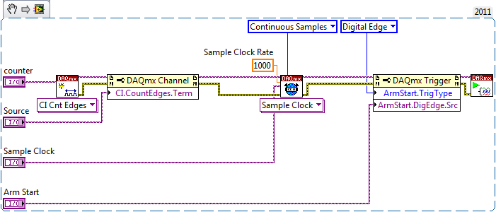
The Basic (from the task) configuration would look like this:
Task 2 and 3 are indeed very similar, using a PFI line for the source, while the other uses the time base of 80 MHz (or some time base internal you prefer).
Best regards
-
How to display any signals in SignalExpress read mode?
Problem: Read showing only 1 block of samples instead of ALL the samples taken when I click 'run '.
Installation program:
Monitor / Record:
DAQmx acquire analog input (Acq Mode: continuous, 1 k samples @ 10 kHz).
Create an analogue Signal (Signal DC 100kS/s, 1000 sample block size),
DAQmx generate analog output (N samples).
Reading: Same steps as monitor / record, except DAQmx generate analog output is continuous samples 1 k samples at 10 kHz.
I dragged my data in the folder of papers according to the Instructions of Documentation Help '5. Read the data.
All data is correctly written to a PDM file and converted to ASCII. How to see the length of reading?
Use: LabVIEW SignalExpress v2.5.1 Lite, NI USB-6221
It is a very requested feature that you can't do in SignalExpress - yet. One solution is to view the log monitoring/recording mode. It is not ideal, because you can only browse the signal not to analyze. Our apologies...
-
Syncronize to acquisition of data with the generation of signals
Hello everyone,
My request is generate pulses on the output of two different to drive two LEDs and acquire detected pulse signal amplified photodiode.
Actually pulses are generated by starting the writing on the analog output, and then start the acquisition (I need 200ms on average), stop the acquisition, turn off the driving LED and develop the acquisition and record the results.
All this in a cycle it takes about 1.5 seconds to run.
Next step would be to drive the outputs with a waveform (duty cycle of 50% of width of 250 ms) and acquire the signal of the photodiode in synchronization with the edge of the pulse.
I tried to use the trigger function, but the examples are not clear on how to do it.
I use NI 9205 or 9215 to acquire signals.
Is there a particular entry to be used as a trigger?
Thank you very much for your attention
Hello
I found that NI 9205 has inputto that one be used as trigger signal, i.e. AI0.
At latest
Eugenio
-
How to convert an analog signal into digital signal
Hello
How to convert an analog signal into digital signal, such that each sample of the analogue signal corresponding to 1.2V will be represented as '1' digital signal and other samples of the analog signal (which are not 1.2V) will be represented (converted) ' 0' in the digital signal.
And how to view the wavefroms or graphical indicators signals.
Thank you.
If you have 1000 samples and you want to convert to digital, you get 1000 digital values. Attached, that's what I mean.
-
Output signals controllable DAQmx (real-time)
Hello:
I have a question here.
It is quite difficult for me, and I can't find any bad example and discussion.
Hope that some people give me some information for me to look it up.
--
I am trying to generate an analogue signal into a DAQmx device (I have an and uses it well) to control another device.
The output signal must be the sum of a background signal (which is decided, let's say a sine wave) and another control signal.
The control signal depends on the entrance of real-time control, for example by using the horizontal location of the mouse to the value of the signal.
The background signal is designed in advance and it will run continuously (should not be stopped once the system starts to ensure that synchronization between each devices).
At the same time, the control signal should be continuous. (if there is no new entry, it uses the default value or the last entry).
--
I have almost no idea on how to do it.
As far as I know, needs only one daq task to write the signal, and then she runs after.
The control signal is a thing in real time, so the task needs to be updated very quickly.
But regeneration tasks cost 50ms ~ on my computer (and I used the low levels rather than the DAQ assistant Renault).
Also, in this case, my background/control signal will be be stopped every time that when the task is regenerated (and this makes my synchronization failure.)
I checked DAQmx in real time, but couldn't find a few examples of tris and seems it isn't for my application actually (?).
A possible solution, I came is cascading my two signals once they are generated by my DAQ hardware. And then I can use an a/o to be the background signal and use an another a/o to be the control signal.
However, my control signal is always interrupted between each loop, and the method of external cascade seems not smart.
Or data acquisition is not perhaps suitable for this application?
--
Hope that some people give me some information and then I can check their.
Thank you very much
Hi Jhensi,
How the example provided was for you?
With respect to the delay that you experience, there is always a slight delay incurred as a result of underlying driver DAQmx running in the background.
In addition, your USB 6611 will have inherent delay due to being used as the communication protocol USB bus. There may be up to 100ms latency in some cases with USB 2.0.
This driver requires a certain amount of time to change the type of output signal, that is production.
A user will never really feel a 'Real-time' experience when you use an application that uses DAQmx. Deterministic control applications almost always use an FPGA with a real-time embedded controller.
It is possible that other delays are due to timing considerations in your code but if you checked these it may be a hardware limitation.
If you could let me know how you do that would be great.
Kind regards
-
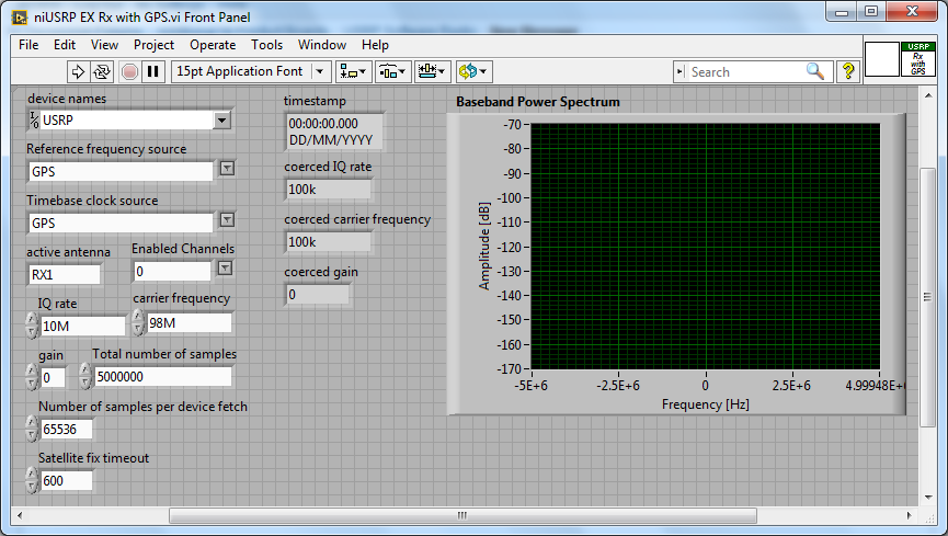
Acquisition with USRP 2953R of the GPS signal
Hi all
How can I configure a 2953R USRP receive GPS signals? I have an antenna VERT900 connected to the GPS ANT of the USRP port, but in the example VI 'niUSRP EX Rx with GPS', I can't reference this port in the field 'Active antenna'. I put only things like TX/RX or RX1 etc. Should what values I put in other areas as well? I know that the L1 band is 1575,42 MHz.
Hello
The example you posted shows you how to acquire an RF signal on the ports of the USRP with internal clock RF and sources of reference defined in the GPS.
To make it work properly, you must have a GPS antenna connected to the Terminal on the GPS device and installed in a place that receives a good level of GPS signal.
The other control of antenna on the schema defines the port on which to receive the RF signal.
If you want to capture and analyze the signal GPS (RF) itself, you can tune into the front-end RF (carrier frequency) at the right frequency of GPS band and connect your GPS antenna to the RF port.
You can use the simple niUSRP EX Rx continuous Async.vi in this case (but may not work due to the very low consumption of GPS RF signal)
-
QUESTION: SE 2012 data display returns to the time graph each time
Hello
I have SigExp 2012.
If I try to add a data view and make a pledge of graphic style, thermometer, etc., as soon as I have the right up until it clicks, add my TC chain, the data view returns immediately to a graph time.
In addition, even if I use the graph of time, once I added the signal, it only let me see the string in a table, a chart of time or a waveform graph. Those are the only choices.
If I use a graph of time or a band of waveform graph, it does not read the signal correctly, but I can not configure the data view, the way I want it.
Is this a bug or I do something wrong?
Thank you!
This occurs when you try to change the display of a signal in its raw format "waveform".
You must convert your signals in scalar format. To do this simply add an amplitude and levels step (under: analysis > measures Time-Domain). Drag this DC signal newly converted to a new chart and right click on the graph to change the display.Honestly, I'm not sure why raw waveform signals are inherently limiting viewing functionality, but in such cases, it is.
You can also; According to the devices on which you use and the order in which you add to your DAQmx Acquire, some default signals step to scalar signals without having to convert.
See the attached screenshot and you'll see how the icons are different between the waveforms and scalar signals.
Hope that helps
-
Problem with the acquisition of signals with DAQ
Hello
I am trying to acquire a signal voltage using NOR-USB DAQ 6008 without using express assistant DAQ vi but the vi gives an error as shown in the attached picture.
I just want to acquire the voltage signal.
Can someone help me solve the error so that I can get to acquire tension using data acquisition.
Thank you.
Hello GoviRe,
Please turn off the running highlight. ("the Yellow lamp" must be turned to off / / 'white')
Your samples crushed, because you are forcing him to crushed to help highlight the execution.
Maybe you are looking for
-
How can I get rid of this pop up?
window appeared... so I deleted firefox, reinstalled and pop up is still there? http://IMTP.me/95dn02jyy
-
HP deskjet1055: how to install the printer to a laptop without cd
Hi, I'm trying to install my printer hp deskjet 1055 to my new laptop hp windows 8? Can someone help me please, I do not have the cd.
-
New Sansa Clip + turns, but in a foreign language
New Sansa Clip + never gave me the possibility to choose the region or language. Later, I tried to manually "Reinstall" the latest version firmware to restart, but following the instructions resulted in no improvement. Any suggestions?
-
Just bought a HP mini 1010nr. I love it, except for one problem. When I move the cursor upwards or downwards it jams and this funny little money search rectangle appears at the end of the needle. It's a random thing, however. But there are enough to
-
my printer quit printing black
I do know that if it of a fix but works for now, my printer quit printing black text, color works fine I ended up cleaning the flue by scraping around it with a needle, then I blew in, like blowing bubbles in your pop, just enough for little ink is o