periodic count
Hello!
This could be so easy to implement but not for me, at least not for the moment. I would like to create a counter of CAD that I need to simulate to test a subsystem that I created, for demonstration purposes. It is necessary to be able to count-360 to 360 with a resolution of 0.1 (which is preferable if it can be adjusted as just the need) periodically. IE once a complete cycle is counted [-360,3609], then the County is supposed to start again.
All those put in place before? I really appreciate the help I get.
As always, thanks for all the helpful guys here!
Tags: NI Software
Similar Questions
-
How to set DAQmx period task input terminal
I have a measurement period counter as task created in VB6.0 using Measurement Studio 8.6 and NOR-DAQmx. Is it possible to configure the input (door) to be PFI0 instead of the default Terminal.
Thanks, vecsol...
The terminals of the meter are wired on certain pins on the DAQ card. The door of the Terminal is not set for a 'default', the door of the meter is connected to a certain line of PFI - this cannot be changed. See help NI - DAQmx Device terminals for more information on PFI line corresponds to what terminal of the meter.
-
Need help in the Migration of storage.
Grateful if you can help me with this.
One of our clients have 2 x 4.0 with standard edition license VMware ESX hosts. Currently, the virtual computer files are resided in local hard drive in the respective host. The customer will buy an iSCSI storage and will be attached to the ESX host.
The VM/VM files must be moved to storage. What is the best way to do this given the fact that the customer is having only the standard license. There's a Vcenter server standard is in place to manage these hosts.
It's legal, but for the version that you mention, I'm guessing it won't work any more, unless you upgraded recently from assessment slot license... After the first start of the host ESX 4.0 can't stop the countdown.
Search for "evaluation" in the documentation online here: http://pubs.vmware.com/vsphere-4-esxi-installable-vcenter/index.jsp
You'll see in the first few hits:
Assessment period counts downThe 60-day evaluation period ESX/ESXi begins to count down immediately after that the first time you turn on the machine in ESX/ESXi.
The 60-day trial countdown begins even if the host is fired and you do not use the evaluation mode. For example, suppose you decide 10 days after the first market to switch mode allowed for the evaluation mode. Only 50 days remain of the evaluation period. Sixty days after the first market, it's too late to switch to a mode of assessment being zero days remain of the evaluation period. During the evaluation period, if you put the machine in a mode, ESX/ESXi AdHocPolicyEvaluationMode timer of assessment does not countdown.
To avoid losing the availability of evaluation mode, VMware recommends that before (or shortly after) power on your ESX/ESXi machine for the first time, you decide if you want to use the evaluation mode. One of the advantages of the usingevaluation mode are that it offers lots of features, allowing you to try out the features you're not still without paying additional license fees.
and
Convert an ESXi host in evaluation modeIf ESXi has a license, you can switch in trial mode in order to explore all the features of ESXi.
Procedure1In the vSphere Client, select the host in the inventory.
2Click the Configuration tab.
3Under software, click licensed features.
4Click on Edit next to ESX License Type.
5Click on the product assessment.
6Click OK to save your changes.
-
Compution at level 1 at the split at level 0
Hello
I have a weekly, planning an application. Weeks roll up to the month. There are some features that must be calculated at the level of the month and then divided for weeks.
For example, monthly salary is calculated according to the salary and the % of salary increment.
Monthly salary = salary * (1 + salary increment %)
When there is no increment of salary % for every month, previous month's salary must be made the current month rather than the value of the previous weeks. I tried to do this using the code below. But it doesn't seem to work.
FIX (& DCCurrFiscalYr, & Fcst_Mth:Jun,@LEVMBRS(Period,1)) / * Fiscal Calendar runs from July to June * /)
I am trying to calculate the month and then divided for weeks.
'Monthly treatment')
IF (@SHIFT ("monthly wages",-1)! = #MISSING)
"Monthly Salary"=@SHIFT ("Monthly Salary",-1) * (1 + salary increment %);
ELSE IF (@PRIOR ("wages") == #MISSING)
"" Monthly salary = monthly salary"" - > & Fcst_Mth * (1 + salary increment %);
ENDIF;
)
ENDFIX
Fix (@LEVMBRS(period,0))
'Salary' = @PARENTVAL (Period) /@count (SKIPNONE,@isiblings (@Currmbr (Period)));
ENDFIX
Kind regards
Brig.Hello
Try using @SHIFT in this way:@SHIFT ("Monthly Salary",-1,@LEVMBRS(Period,1))
If you do not specify the month, @SHIFT evaluates the level 0 of the period dimension by default no matter what you fixed.
See you soon,.
Alp -
How to count the edges within the great period of door?
Hello
I use a PXI-6624 counter/timer in Visual Studio C++ with Meassurment Studio.
I want to count the edges on a signal within a high period of an input signal.
I found the documentation entries "CTR n CBC", "CTR n GATE" and "CTR n to THE.My idea is simply configure the counter 0 to count the edges on CBC by blocking via DOOR.
can be an example to my problem in the installation of nor, but above all I do not understand the description of landscaping.
to find a good example, you must know the name of the function you want to use.
can someone tell me the good examplename for my problem?
What call configuration should I use?a little less important than my first problem is a similar.
I want to count the edges on a signal between a start trigger and a relaxing stop.
SRC-> signal
DOOR-> start signal
To THE-> the stop signalI found a way to count the edges of the internal clock between start and stop (2 Seperation of edge), but not for an external signal.
can someone help me with this? especially with the first.
B
Hi John,.
Thank you for your help. It works very well.
I had a few problems with how the timebaseSource should be implemented.
Finally, I found the solution.
for those who do not want to search long for the code, it is here:
Create the task
CNiDAQmxTask ("CITask") m_task;Create the meter inlet channel
m_task. CIChannels.CreatePulseWidthChannel ("PXI1Slot16/ctr0", "",)
atof (minimum), atof (maximum), startingEdge,
DAQmxCIPulseWidthUnitsTicks);Retrieve the channel to change
CNiDAQmxCIChannel chan is m_task. CIChannels.GetAll ();
Fix the DOOR Signal
Chan. SetPulseWidthTerminal("/PXI1Slot16/PFI38");The value of the Signal SOURCE counton
Chan. CounterTimebaseSource = ' / PXI1Slot16/PFI39 ";CNiDAQmxCounterReader myCounterReader (m_task. Stream);
Double measuredWidth = myCounterReader.ReadSingleSampleDouble ();Thank you and goodbye
B
-
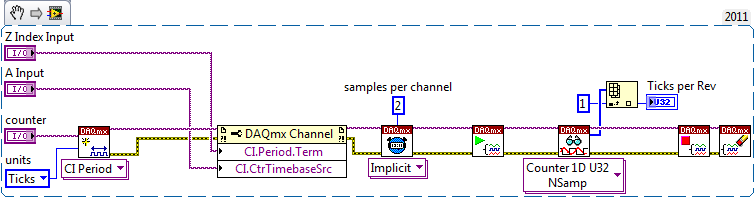
Count of edges within a period
Hello
I'm still fairly new to labview and that I could use help on something, I'm working on.
I need to measure two things of an encoder, the RPM, which I can easily do it through the index; and the number of edges on the channel between two pulses of index.
I would like to use the index to trigger the counter to start to count the edges on channel A, then the index following the end of the counting. This program will essentially allow check the speed of ROTATION of the encoder based on a basic speed, and it will check for the proper resolution of the encoder.
I use a NI6602 counter card and I need to be able to set up several top encoders that's why I'm only using the index and the channel has.
Thank you
Jason
You can either:
Configuration of the task as a measure of the 'period' (measure the period of the Z index by channel A time base):
OR
Configuration of the task as a measure of "County Board" (count of the edges of a signal using the Z index as the sample clock):
OR
Configuration of the task as a 'encoder' measure (measure the change in position in terms of A / B ticks using the Z index as the sample clock):
But the example of encoder, you probably want to configure the digital for each input filtering as encoder in all signals are often quite loud (sometimes the noise is detected as additional edges that would shake your meausurement). In the example of the encoder, it is probably not necessary given that the meter is incremented only once a cycle of A and B even if you still need to beware of noise on the Z index signal.
Best regards
-
Data acquisition period log rate Counter
I measure and record the duration of a pulse train of digital entry (entry to the NI9421 card on a DAQ, series "C" chassis and recorded via LabVIEW SignalExpress 2009). The acquisition stage 'Counter period' is configured to use ' 1 meter"measuring method.
In order to save the data that I have to use ' 1 sample (on request)"acquisition mode.
When I go through the saved data, how can I determine:
(a) the sampling frequency of the recorded data points?
point b) absolute timestamp of all the data?
The log file has no information concerning the frequency of recording and my experiences, it seems to change based on the measured period of entry.
Any ideas?
Hi a.yearsley,
Counters on cDAQ chassis 1st generation (9172) do not support measures clocked sample period. I assume you are using this chassis since you mentioned that you have the module in slot 5 or 6.
Your County of edge is very similar to the method of meter high frequency 2. In both cases, you specify a length of time and count the edges of your external signal during this period. The 2nd counter is used to generate the gate signal for the duration of time specified. Your error with this method is up to 1 time of the external signal, it is more commonly used with higher frequency signals (I don't know what is the frequency of the signal).
The standard method of 1 meter counts the number of ticks to a time base internally (80 MHz) for a period of the input signal. As the signal itself, it is what is blocking the measure, the sample is locked in the buffer on the edge of the signal and is not clocked independently. If you wish, you can configure the implicit synchronization, which gives you a period measured for each face of the input signal.
Taking the stage above an idea more far, you could just set up a task to County of edge with the time of 80 MHz as the source database. Use the external signal as a sample clock. The only difference between this and using the standard period with implicit synchronization measure is that the counter is not reset after each sample. This could make it easier to follow if you want to save a sample all the x seconds (that is, once the total passes a certain value). You can find the period by subtracting the consecutive numbers and multiplying by the period of the time base (12.5 ns). The meter would be turning after 53.69 seconds about, but if you read the County under the name of U32 there will be no problem with the subtraction (0000 - FFFF = 1 if the numbers are 32).
If you're on cDAQ chassis 2nd generation (e.g. 9174, 9178, 9188), then you have not actually taken in charge for a period clocked sample measurement. You can choose to enable a medium or not. The user manual 9178/9174 has diagrams showing the extent of the clocked sampling frequency that is essentially the same thing (the driver reverse the measurement period for the frequency). Must be guaranteed at least 1 m from your external signal between the sample clocks, if you use this method. The clock can come from many sources - I would probably recommend using another counter to generate.
Best regards
-
Create a virtual channel that increases a counter for each iteration of a cyclic load test
We will be a long period of cyclic fatigue tests, and I wish I could keep track of which iteration we are on this block. The current plan is to test for 10 hours at 15 Hz, and then stop test for 2 hours for an inspection of the structure. Later tests will begin upward. Each of these blocks of 10 hours can start at a number of 0, but I would like to follow the release of our cell so that when he sees a rising edge (with filtering to take account of any noise) it will increase a 1 meter. Each sample will then save this number in a column in the data file. It doesn't have to be perfect in the measurement on the forehead, he sees the new cycle, but there need to be specific in the way that it is not miss or as an additional cycle.
Is something like this in Signal Express full?
Yes, what you are proposing is possible with SignalExpress full. You can call LabVIEW signal express code, so call a LabVIEW VI, which contains your counter code is a way to do it. If want to do entirely in SignalExpress you can use DAQmx features by browsing up to add a step > acquire signals > DAQmx acquire and put in place a task entry counter to match your needs.
-
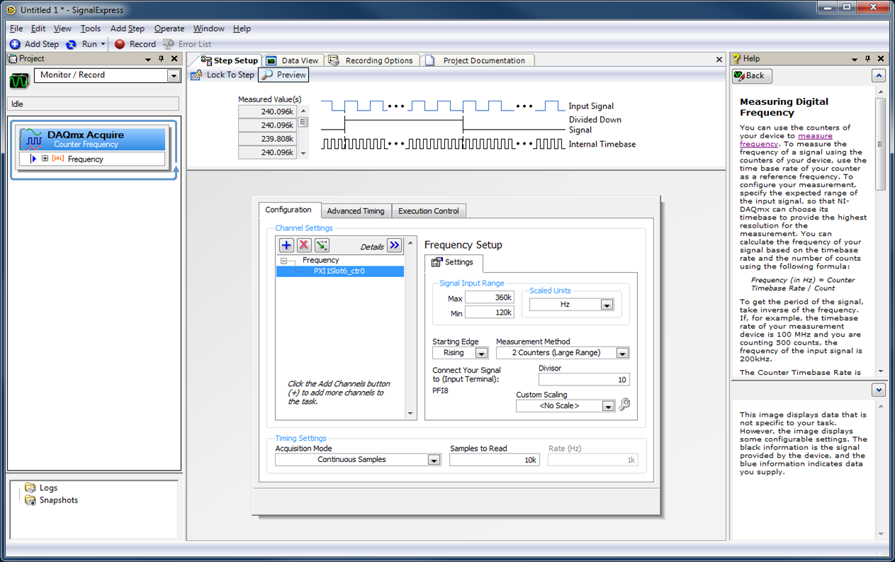
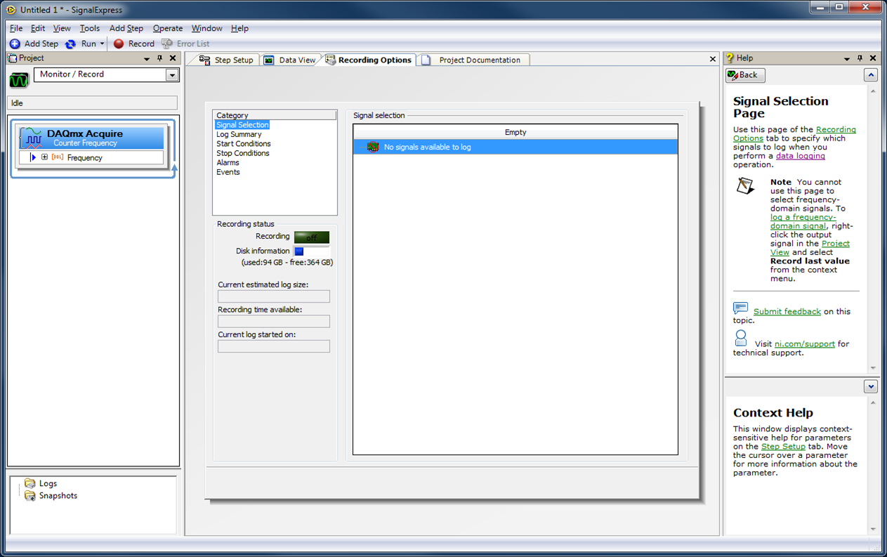
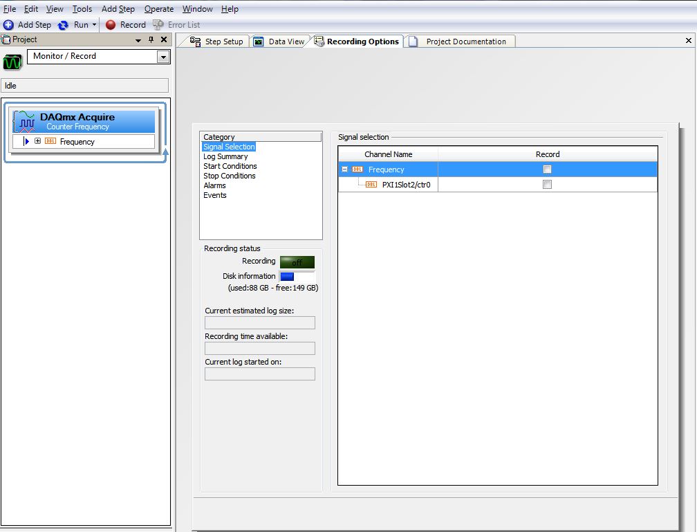
Can't the Datalog (counter) frequency data in 2014 SignalExpress
I'm looking to acquire data from a map PXI-6143 using SignalExpress 2014. I am the acquisition of measures of the frequency of one of the built-in counters. However, SignalExpress does not show this entry as counter available for data entry. See the attached picture for my setup:
On the tab "Options", he says "no signals available to open a session. Any ideas what I did wrong?
Change your method of acquisition for 1 sample on request and define your sample in seconds period.
I think IS don't like continuous samples when you work with the frequency -
Hello
I'm reading pulses TTL of a generator of service using a meter. I apply a 1 kHz signal to the meter. Each time counter reads the pulses correctly in the first cycle of measure, but it lacks some counts in all subsequent cycles.
I use NEITHER 9181 cDAQ chassis and NI 9402 module with 2014 LabVIEW and NI Max 14.0.
My computer has the Windows 8.1 operating system.
Please find the VI joint and the front image after EXECUTION.
I also used the same VI with chassis USB cDAQ-9171 . Results have been improved, but the same problem persists.
What could be the reason for this, please guide.
Thank you!
B. Sharma
1. the loop time is defined by software and therefore won't be compatible.
2. you restart the meter patch between each iteration of loop - so that the task is restarted, it does not take samples. The new start is faster on the USB device from the device ethernet due to the latency of the lower bus, so that explains why the behavior is improved on the 9171 compared to the 9181.
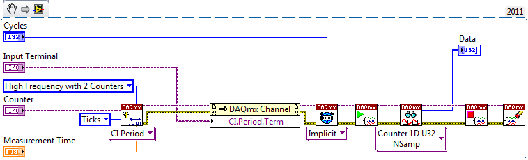
Using method 2 meter would be a clever way (maybe too smart...) to implement which, according to me, you are looking:
This will configure a second counter (ctr0 is paired with ctr1, ctr2 is paried with ctr3) to generate a signal of a period known (time measurement). The meter is taken into account the number of external pulses during this period, and since we are because data in terms of 'Ticks', it will give you the number that occurred during the measurement time. This measure is repeated for the specified number of Cycles without software-timing or latency between cycles.
The appeal of reading will have a time-out value long enough to ensure that all cycles have completed (or you can query to see if the task is made first of all to give the user the option to cancel the measure).
Best regards
-
Helps the acquisition of photon counter data using LabView 12
Hey all,.
Student graduate Chemistry here new to LabView and are looking for some help moving in the right direction. I'm looking for help with connecting my meter to 12 LabView for data acquisition of trace-fluorescence photon PerkinElmer SPCM-AQR-14 (now owned by Excelitas Technologies). I just want to be able to acquire number of photon counts vs. time. Currently, I installed a PCI-6601 and use a BNC-2121 to connect the BNC of the sensor output. The detector has a pulse output digital TTL with 30 ns pulse width, and by contacting technical support on this issue, I was told that this pulse width was too short to always detected by the 6601, but can still go ahead and give it a try. Basically, if everyone is familiar with how to start with this configuration, ANY help would be greatly appreciated. As I said I'm all new to LabView and am currently spend all my spare time reading manuals and help files.
Please let me know if you need any kind of information to make me understand what I'm doing.
I would say something like this:
A measurement period the registry account out of the entrance of the samples as well as gives the meter. You will basically measure the 'period' of your sample clock fixed regarding ticks of the external photon signal.
According to the downtime, you may need to re-read several samples per loop so that the software can keep up with the incoming data. Also, the first sample is not useful because it represents the County between the software from the task of entry of the meter and the first clock signal - you should disregard/erase the first sample (or if you want you can set up a trigger to begin arms).
To do the same thing by using an edge County task would require using both the sample clock AND a counter reset signal - this not is not supported on 6601/6602 (even if it would be possible to set it up that way on a device of STC - 3 as a series of X).
Best regards
-
Function DAQmxRegisterEveryNSamplesEvent can be used for the counter input channels
Hi all
I have a request to count the number of digital pulses. I want to know the time of impulses coming which start from 1 and an increase in later, 4 as 1, 5, 9, 13... The time interval between each pulse is not a fixed value. So I tried to use DAQmxRegisterEveryNSamplesEvent and DAQmxCreateCICountEdgesChan functions. But afterI calls the DAQmxStartTask function, it has always failed. The advice that I used is the NOR-PCIe-6320. Here's the part of my code.
DAQmxErrChk (DAQmxCreateTask("",&m_taskhandle));
DAQmxErrChk (DAQmxCreateCICountEdgesChan (m_taskhandle, "Dev1/ctr0", "", DAQmx_Val_Rising, 0, DAQmx_Val_CountUp "));
DAQmxErrChk (DAQmxRegisterEveryNSamplesEvent (m_taskhandle, DAQmx_Val_Acquired_Into_Buffer, 4, 0, EveryNSamplesCallback, this));
DAQmxErrChk (DAQmxStartTask (m_taskhandle));I don't know the reason. Can someone give me help. Thank you.
Yang
DAQmxRegisterEveryNSamplesEvent only works with the buffered in memory tasks. That's what you should do anyway (if you want to use the callback or not):
1. make your external signal the sample clock (DAQmxCfgSampClkTiming).
2. use one of the basics of internal time as the source (DAQmxSetCICountEdgesTerm).
Each sample you read will give the count in ticks of the time base. Multiply the number by the base of your time period and you now have a timestamp. Keep in mind the counter roll to 2 ^ 32 therefore account for this in your program.
The recall is not necessary, but it is useful that you can make sure that you block your main thread until the samples are available.
Best regards
-
Why does the period display NaN? What does it mean "NaN"?
I have a vi that is supposed to measure values of period 3 and 2 tension using DAQmx. The vi is attached.
When I run the vi, I get no error, but one of the counters display NaN instead of a period (in seconds) value. Why would this counter not appearing? See the .jpg image of the screenshot, which shows the lights on the front panel, after execution and stop the vi. Note that the period 2 shows "NaN" but, period 1 and 3 show a real value. "NaN" only displays in "period 2" executing too. ' " "Period 2" never displays a numeric value. Moreover, as "NaN" actually mean?
Appreciate your thoughts.
Thank you
Dave
(using 3 counters in the cDAQ-9174 and the module OR 9401 plugged into the chassis cDAQ; periods are measured from the encoders)
NaN means not 'a number '.
In your code, Mean.vi will return NaN (with the error-20003) if the input array is empty.
What happens if you connect the signal of the 1 meter or 3 to counter 2? If NaN disappears, then there is a problem with the signal currently connected to the meter 2.
- Your current code, using usrs to (unitialized shift registers), will produce NaN when running for the first time.
- The size of the usrs to will increment at each iteration.
- If your VI is used as a Subvi, the means will be bad for the first 15 iterations since they will be calculated with the values of the usrs to--> previous lengths.
You must use PtByPt.vi means that will calculate the average of the X last values without above mentioned problems.
-
AI sample clock using to Trigger counter samples
My basic question is: the ai\SampleClock signal is active only during the execution of a task of analog input?
The details are:
I have a multifunction data acquisition card series X PCIe-6321. It is controlling an SCXI chassis and has a module SCXI-1180 and SCXI-1302, so I can control the analog inputs of the chassis but also access to the meter 4 on the map. My application requires that I use all 4 meters to measure a frequency input signal and synchronize the samples for the analog input signals. I created 5 tasks, 1 for AI and 1 for each counter.
I'm using LabVIEW 8.6.1 with the latest NOR-DAQ drivers on and the operating system 64-bit Vista
1 are there drivers or hardware restrictions that cause this solution does not work?
2. can I use the ai\SampleClock as sample clock of entry for each task frequency? If I do this the beginning of sampling will be synchronized? I.e. If I each task frequency first starts, they will wait until that task to HAVE it is started before you start sampling?
3. If this does not work, do I need to send the sample clock of the task of the AI to a line PFI (PFI1) and then use it as the special frequency sample clock input?
I used to do option 3 when the synchronization of two cards in PXI chassis and use only the beginning of the task of the software instead of synchronization on a digital departure, given that the sample clock will control samples anyway. I need to know if the same behavior works with the above scenario.
Thank you
Bob
Prolucid Technolgies Inc.
Hi Bob,
I can confirm that the AI/SampleClock is available only during the execution of the task to HAVE it. As far as other issues go:
1. you must provide more information on what you seek to do exactly, but there is no problem with the clock of the task of analog input sampling to be used with routing counters. I had read through the section of the X series operating manual which deals with the measures of frequency clocked at sample (see page 7-16) for more information about what really happens during this configuration to make sure that it suits your needs.
The frequency of the signal to be measured must be at least two times faster than the sample of your task clock to HAVE.
2. you can indeed pass the signal on all four tasks at the same time (you can check the page peripheral routes in MAX to ensure the routing restrictions). Sampling will be synchronized four counters are started before the task to HAVE it, but counters will be armed at different times unless you configure a trigger to begin arms (see page 7-45 series X operating instructions). I would consider using the AI/StartTrigger if you want to do.
The effect of not to arm the counters at the same time would be a different number of periods on average on each counter for the first sample (assuming an average is enabled). Maybe it's not a major concern, but I just wanted to point out.
3. the itineraries are available inside the Board of directors so external routing is not necessary, you can simply specify to use the sample clock of the AI for each meter clock and roads will be done for you. If you want to export the signal on a PFI line and new route on another line PFI, this option is also available for you, but shouldn't be necessary.
I hope this helps you get started. I'll make sure to take a look at Chapter 7 of the X series user manual, if you have a chance as he described how all configurations of meter of working more in detail. If you have related questions do not hesitate to post in return.
Best regards
John
-
Hello
I use a mx-acquisition of data (NI USB-6211) and I would like to use it to generate a pulse of digital modulation
that is triggered by an analog input signal. The input signal is a pulse of squares analog modulated
What is almost periodic. It's because of my set up, and I can't do anything with it. I would use the
before the edge of this signal to trigger the production of a digital pulse signal modulated (0-5 V). My
problem is summarized in the figure given in the annex. I would also like to have the possibility of
Configure the 'backwardness' and the term of "TAU_LED", while the VI works.
I have looked at several examples of instrument OR meter generation, generation of PCI I / AO, but doesn't
not managed to solve my problem. Does anyone have an idea of how start with my problem? Are there
No matter what example VI that I could start to change?
Thanks in advance,
Gregory
Hi Gregory,
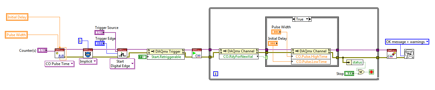
Sorry I forgot to mention: the Initial delay applies only to the first impulse of a redeclenchables generation. Every subsequent impulse will use low time as the Initial delay. I agree the behavior is not very intuitive (our latest guidance of series X actually supported an Initial period to allow on property Retrigger), but it is described in this knowledge baseand should also be mentioned in the DAQmx help.
As you generate just a single pulse, I would recommend simply connecting the Initial delay and at the entrances of low time to the same value for each pulse will be delayed further.
Exit tasks ongoing counter currently supports DAQmx writing. However, the finished generations or simple impulse are not. However, you should always be able to get the behavior you need with a property node DAQmx. The current solution on the series E/M is:
Again, this is not the most intuitive, but I checked that it works on my 6210. After writing a new value in the software the pulse will be updated on the 2nd trigger. Attached is the code stored in LV8.2.
Best regards
Maybe you are looking for
-
IPad showing 9.3.5 as the latest version of ios
I updated my phone and watch the last ios. However, when I look for the update to 10 for my iPad, the device checks the update and repeat me that it is using ios 9.3.5 and it is up-to-date. This happens when I use the general tab on the settings as w
-
Toggling off "autoplay to authorize" in settings does not work on some Internet sites. PCWorld.com is an example. I'm doing something wrong or if this feature is broken?
-
When I used to open a new tab it's a blank page, but now a link to a website mystart.incredibar.com. How can I get rid of this and get back on the new tab page
-
status of app store of the mavericks is downloaded - I need an up-to-date copy - certificate has expired on my copy
-
Error 0x800ccc0f of Windows Mail. Could not receive new e-mail messages.
original title: windows mail Error 0x800ccc0f Hello fantastic support network. Read these previous responses, but none of the work steps or apply here. It is a January 2009 HP Pavilion dv6-1030us notebook PC that is pre-installed with VISTA. I immedi