PID motor problems
Im having trouble with an application of linear motor control. I'm using a servo-motor/converter to power a linear drive. The player is running in current/torque mode so that the output power/force is proportional to an analog input that is sent to him (no setting parameters). For this particular application, Im using the express vi 'set up fake signal' to create a waveform of sin that is used as the target value then inturn helps determine the voltage sent to the engine and thus, out of power. The tension of a load cell is then read through PCI-6014 and convetered at a level that can be compared with the output of analag, scale factor for the torque mode. There is also a PCI-6601 used to determine the position, but should not be relevant here.
Without PID. Using a load cell, I see that the wave of fishing is truncated at the top and bottom, it rises to fast in response to the tension and then from the trays. The reverse happens when unloading and it reaches a low load to soon and there is also the truncation. I will attach a figure which can demonate the problem better than I can explain it.
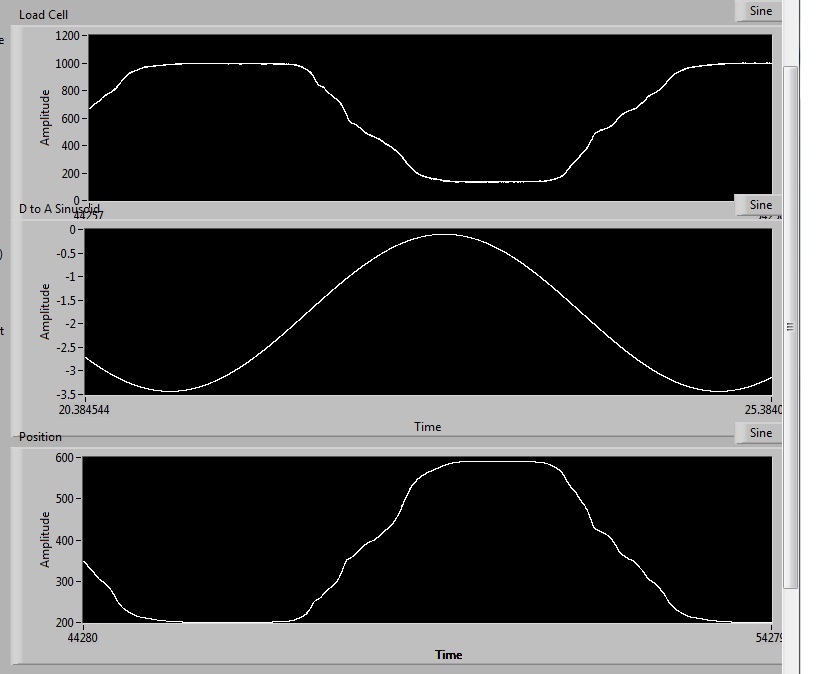
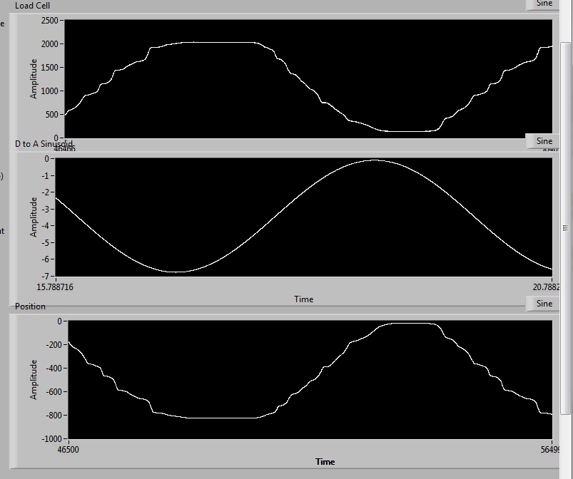
Without PID. This isn't a saturation effect, but as I can raise the amplitude of the input voltage and the force will follow the same type of waveform, but again the load levels. Ill. attach a screenshot 2 new levels of load of 2000lbs.
I can look at the levels of current/voltage output of the command servo which feed the linear actuator and that they are the sinusoids perfect, after all what is the input voltage, if guided by PID or not, its a mirror right, without truncation as occurs in the above figures. There is also no problem of speed or acceleration, it is well under the speed limit, that this system can work, IE under 0.25htz and it can run 50htz to these displamcements. So, these are not the problems.
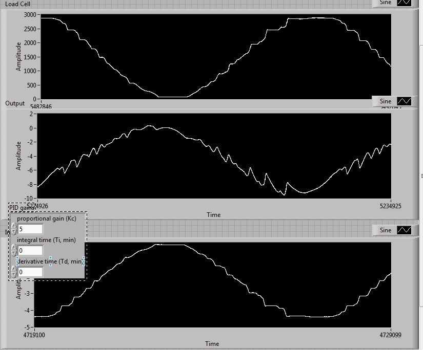
As I understand it, the PID is commonly used to correct this type of problem and is standard with machines that need to produce force in this way... Infact, I learned from the people who make the drive I use to fix this type of problem. Yet, Im could not get it to work. I tried to change the P term accoring to the N? I have the document below and dosent seems to correct the loss of crete, so Im doubtful the I terms or D will do much (and have tried without success). I'll attach a third screenshot and link in the general guide for the PID below
http://zone.NI.com/DevZone/CDA/tut/p/ID/3782
with the PID, with P increases so some departures of instability
Ive tried reinstallilng labview on a different computer, with PID and get identical results.
I'll join the code I help him, not that I'm waiting for anyone to find, its big enough.
Any help is greatly appreciated.
Jimmy,
If your control loop does not work with a deterministic timing, the highest rates of change of the setpoint to the situation, so the quality of the control loop also limits the frequency of your sinuses. However, the loop itself is always on to 2 kHz, so the loop time and jitter of the same order of magnitude, then it will be very difficult to get a system of stable control with this configuration. Reduction in the rate of control loop is also not a solution, because the linear motors are very dynamic systems, requiring control loop series kHz.
To improve the situation with your current setup, you can always try to better structure your vi, delete dynamic memory allocations and so forth, but the improvements will be very limited. In fact, there is a reason why NEITHER a lot of success with products such as LabVIEW RT or compactRIO and the reason is the deterministic behavior of these platforms that is required by the dynamic closed-loop control applications.
To answer your question on the amplitudes: regulator PID tried to generate an output signal, which translates as the set value - PV = 0. So for example, if your load cell outputs 0.5 V/N and you want to generate a force of 10 N, the set point must be set to 5. In other words, the scales of the setpoint and the PV must match, but this does not mean, you must necessarily across the PV before you go to the PID controller. Instead you might evolve set points to map to the copying. The advantage of this approach is the fact that you don't have to do calculations online on the feedback signal, because you could precalculate a set value table before you start the move. This approach would calculate you your calibration data in the matrix of setpoint values.
If you follow this method, you might also think of using a control chart of standard movement as a PCI-7352. This Council deals with all onboard, real-time control tasks so no LabVIEW RT is necessary and you can move the locker bays precalculated in the memory of the Commission (contouring mode).
I hope that gives you some ideas how to proceed from here.
Kind regards
Jochen
Tags: NI Hardware
Similar Questions
-
I NEED SPEED CONTROL A 120 V UTILIZANDO LABNIEW CON POR EL PUERTO USB PID MOTOR
: manindifferent: HOLA A TODOS, ALGUIEN CAN help ME A PROGRAMAR EN LABVIEW EL CONTROL OF SPEED OF ONE MOTOR DE CORRIENTE ALTERNA OF 120V. I NEED THAT TENGA EL PID Y Q SE RELEASE POR EL PUERTO USB CON EL PIC 16F628A U OTRO MICRO... ESTE ARE A HMI PROJECT...
GRACIAS POR SU POST... :-)

Hola Barcelona
No you tiendo very well the pregunta respecto a en parte that need help.
Respecto a lo del PID against este foro el cual tiene links in con PID information y controls Motors DC aunque vayas a usar para a CA, information engine you can be util además TR el control going to use usas UN PWM igualmente you serviria mucho gran parte the ahi esta info.
Command PID made al control of DC motors
Respecto al PIC the Comunicación y, mi primera mid-week seria using a PWM con UN cDAQ o una tarjeta and NO esa manera you mas eficiente el sistema control resultaria. Lo contrario seria UN media series utilizando el cable USB utililzar. O the third option you puedo recomendable usar UI an Arduino para which are hay una libreria Comunicación con cual ordered using LabVIEW seguir y UN mircontrolador sin tener as complicarte mucho.
OR LabVIEW Interface for Arduino Toolkit
I hope this information you sea util
Saludos
R. Esteban
-
So I got my Apple Watch (42 mm Watch 2 OS running) for a little over a week now, one day my engine haptic started vibrating hum of light. Today it stopped working all together, I put it on this morning had all my notifications as normal, but after 3 hours of wear, I received a notification with sound but no haptic feedback. Everyone knows about this problem? reset has seemed to help for a few days, but why it is happening? I feel like mine is defective
Hello
If you have not yet done so, it may be useful to update your iPhone and Apple Watch for the latest versions of software (currently 9.2 and watch OS 2.1 iOS).
- Update the iOS on your iPhone, iPad or iPod touch - Apple Support software
- Update the software on your Apple Watch - Apple Support
Otherwise, it can help to disable the twinning and re - pair your watch. The app shows on your iPhone shows backups automatically, including a new when the disparity with the app choose this option to restore the watch (backup restore) when provided the opportunity during the whole. Most of the data and settings will be restored, with a few exceptions (for example cards Pay Apple, access code).
- Pairing your Apple Watch and Support Apple - iPhone
- Set up your Apple Watch - Apple Support
If the problem persists, contact Apple support (mail service may be available) or make a booking Genius Bar in order to have your watch repaired under warranty:
-
Hi guys,.
Im a software using advanced LabVIEW PID and hourly programming. But as my gain change, the output does not accordingly with my gain. For example:
Error = 10
Gain = 10
Output = 100
Then
Gain = 0, 01
Output = 100 supposed to be output = 1
Looks like transfer smoothly? I couldn't tell.
Yo have any idea why? The VI of "PID Gain schedule example" change accordingly with the error output. But mine is not. I hope you guys could help

Not the Gain annex vi does not change your output according to the entry it will select all of the gains that you want to use. In a certain type of profiles, we will have to use a different set of earnings, so in these cases, you can have a different set of gains and which apply accordingly. For your business simple PID must be suffucient.
-
Hello
I have a question to the Menu/submenu.
IAM sure you can help me.
In the screenshot you can see my menu with the submenue.
I would like to know how to chance the arrow under the "events"? I would like to have the arrow on the right site of the word "meetings".
How can I do?
Thanks for your help.
Anett

To align the text in the left menu, you can choose the option "text left alignment" after selecting the menu.

Thank you
Ankush
-
The 12v DC motor PID regulator
Hello world
I want to order a motor to power DC 12v by using the PID control 8.2 toolkit.
-a closed-loop control system
-using a DAQ model: NI USB-6008
-How to control of motor speed DC 12v with PID control
Im stuck to get pid.vi and I wanted to know what the problem is.
pls help me on my problem, if can pls an example VI for me
Thank you!
Well, there are a lot of things you need to do this, the software LabVIEW being only a part. First, most of the DAQ cards will be not enough power source to actually power a motor, especially a USB6008, so you will need a form any driver/power of the amplifier. For closed loops, you will need feedback to tell you what the rotation of the engine is usually a wheel split with a LED and a sensor (if it is a school project or hobby a source you could look at is an old mouse wheel). With these two you so a way to drive the motor and then detect its motion. Then you can get the idea to PID, which takes the feedback (regardless of the sensor to find you using the) scaling so that it matches that you use and apply to one of the PID equations to match the target value.
-
Command PID made al control of DC motors
Hola a todos
Alguien me could asesorar con el uso del PID toolkit there that manera lo puedo more al control of 2 DC motors, con doble cuadratura encoders
Buenos dias, Diego,
SIGA el enlace para descargar el PID Toolkit. Any pregunta por favor póngase in contacto con nosotros.
LabVIEW PID and Fuzzy Logic Control Toolkit 6.0 - update for LabVIEW 8.0 - Windows
http://Joule.NI.com/nidu/CDs/view/p/ID/603/lang/en
Carefully,.
-
Problems with encoder motor switching noise readings
Hi all
I wanted to ask advice with a hardware problem which seems to be pretty common.
Here I describe my request:
We are controlling an electric actuator for robotics application. We use encoders to take position readings, and we need to perform analog acquisition for other measures (for example, the force measured using strain gauges).
The problem is:
In summary, I have problems to properly acquire position readings of a linear encoders quadrature and also a few analog inputs. The cause is the switching noise generated by the drive motor that we use (which is an engine without Stricker of CC Moog BN-23-23).
Our acquisition platform is an NI PXI-8106 with a PXI-1042 q chassis. We have two possibilities to acquire the signals. We have a multifunction DAQ series NI PXI-6259 M and a FlexRIO NI PXI-7951R with one module DIO NI PXI-6581R.
The switching noise have a frequency of 30 kHz. In a scope, we see a series of peaks of noise which are present only during a short period of time (approximately 1/10th of the duration of the noise). The rest of the time the noise is not present.
The Accelnet amplification module that powers the electric motor gives us a clock signal synchronized with the noise (whose frequency is approximately 1/4 frequency noise). This clock signal provides a way to solve the problem of analog acquisition. We can use this clock to make an acquisition stamped with an external clock in LabView connecting the clock on a spit of PFI or FPGA card. But the noise is also corrupt this clock signal (we get an error daqmx us warning of possible defects in the clock signal and also to stop the acquisition). I believe that to solve the problem of encoder we can also solve the problem of the analog acquisition.
In the encoder readings noise makes our County to counter upward or backward gradually fast enough. We can get an increase in the position of about 10 cm per second with no appreciable movement in the linear actuator.
It would be a great help if someone could put the solution he uses to solve this problem.
Thanks in advance for your help,
jespestana
PS: I stress my conviction that we have a hardware problem, because we have only bad readings when the electric motor does not work. I am therefore convinced because we have already done reading encoder and analog with the help of other players, such as hydraulic cylinders. So, I think that it is not a problem with our software (of our LabView VI).
Hi jespestana,
I don't know why the noise could be the cause of your encoder can increase more slowly... However I have a suggestion on the map of the M series (6259):
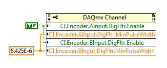
M-series cards have a digital filter integrated on the lines of the PFI (see the user manual of M series). Looks like the noise is a series of 3 ~ US of impulses (1/10 to 1/30 kHz). Of the available filtering frequencies that you can set on your M series is 6,425 US, which must ignore the impulses (high or low) that are less than 6,425 US. You can configure the digital filtering with a property node DAQmx:
One caveat is that the driver only allows you to configure the digital filtering for entries counter on M Series devices. For example, you can use a digital filtering directly on your task of encoder, but not for your sample clock HAVE. A workaround can be found here, which is to set up a dummy counter job to define the PFI filter for your task to HAVE. If you use the same PFI line for your encoder and the task to HAVE it, you should be able to just set up the PFI filter through the task of the encoder and worry for the workaround.
Regarding the RIO Flex, I think that you could implement something similar on the FPGA, but I'm probably not the best person to comment on this subject. It would be probably a lot more work to use the DAQmx API's built-in filtering.
Best regards
-
Hello.
I have a problem with my design of State machine and I need help to know what to do.
I m using a state machine six steps for HVAC test machines. Password-> Idle it down-> Run-> Acquire-> Report--> Shut. Run and acquire the States have PID controls in them (almost identical States) and very fast three-way-valves they´re for the desired control of the temperatures of the water mixture. I m running try to get static values for temperatures and I m satisfied with them, moving to acquire the State to get the data in the report. My problem is that when the race to acquire, PID control outputs from scratch and at that time there static temperatures have disappeared. Worst case is that the tested machine HVAC stops following liquids from bad weather and I start from the beginning.
Is there a way to tell the PID.vi the release of starting a specific value? In this case, continue to the last value that they released in the State of enforcement?
I know that scheluding of gain would do (machines would be not closed) but I Don t want to use it because the original problem would still be there.
Arctic_Fox wrote:
So PID vi:s remove from the state machine, placing them inside the while loop that surrounds the state machine and leaving all necessary writing DAQmx-functions inside the race and the States Acquire would make corrections on the positions of the valve only on those two States. Right?
It is a good idea. I leave the DAQmx functions outside the state machine as well. If you need to write a fixed value for the outputs when the PID is not running, use the PID that you already have to determine the value to write (output PID or anything else) on/off switch. In addition, I would make sure the reset of PID entry is true whenever the PID is not running.
-
Tengo problemas con mi equipo no me already access mi red inalámbrica me pide activate the firewall of windows comohago by activarla
Hello
Sorry, this forum is in English only.
Please select the language icon at the bottom of this page
 English and select your native language from the popup list to view the forums in the language of your choice.
If you can't find the language of your choice, support for international sites additional options can be found by clicking on the following link:
http://support.Microsoft.com/common/international.aspx
Concerning
-
Problems when you try to move the 3 stepper motors
Hello
I have problems when I Isaiah to compile a 3 stepper motors control program.
I have 3 steepest motors and controller (3 SMCP33 + SMCP33-EVA) nanotec.com, they also provide an example of Vi to control a motor that works successfully, but problems happen when I try to adapt the program to try to start the 3 Motors. The final application for this is going to be a Cartesian robot XYZ so finally I need to program coordinates to move the 3 Motors.
I am new to LabVIEW, so what I do is try to adapt the nanotec example to order 3 engine as follows.
-J' I assign each engine a different address, doing so that I can run each engine separately. But when I try to run 3 programs at the same time, they work but all moving them the engine (the first that has been run).
-If I try to make a sort of sub - VI is the same thing, only one motor is driven.
-Moreover, I get a warning when I try this, I have attached a screenshot of this.
I have attached the Vi and texture it to improve my description.
I woul be grateful if someona can help aport.
Kind regards.
Thanks for posting the original. By comparing the two screws immediately gives an indication of what might happen.
In the picture you posted you circled two places where you changed the address of the reader. In the Example.vi - Nanotec address of the player is connected to about 14 seats. So when you try to run the other engines in your modified program, the 12 places, you have not changed the address of the player are always preset to motor 1.
What you need to do is to divide the example VI in at least three parts. The first part initialization. The next part moves the engine. The last part ensures that the engine is stopped and made any required another stop. Each party becomse a separate Subvi. Each Subvi has the address of the reader as input. The initialization and shutdown parts are placed before and after a while loop. The movement parts are inside the loop. You can use three of each sub - VI for the three engines or a Subvi combined with subVIs move three to manage all three engines.
I can't say what approach might be better without knowing more about how you plan to order the engines - one at a time or all three at the same time, what kind of feedback is used, how management mistakes and other topics.
Lynn
-
I have a problem with the simulation in Matlab 6.5 and LabVIEW for PID controllers
I have a problem with the simulation in Matlab 6.5 and LabVIEW. I have a few methods for granting regulators PID in MATLAB to go but not of LabVIEW. Degree of international teams of two transfer but when I passed to the fourth degree is no longer working. We have changed the formula to calculate the parameters for the fourth year and gave me some good values for assignment of Matlab, but when I put on LabVIEW are not resolved. the formulas are available in PDF format and are. Please help me and me someone if possible. Thank you
Lim.4 generation in comparison methods and the MATLAB program settings are for the service of transfer to the second degree.Hello Lascarica,
I noticed that you are using the screw of PID. Gains on these screws are based on TIME instead of GAIN. You should be able to build a PID regulator and vary the gains and then compare the results.
-
PROBLEM VIBRATION MOTOR SE IPHONE
I bought the IPhone SE of Sahiwal Pakistan from an importer. Here is not official Apple store in Pakistan. Guarantee of the iPhone WILL be completed in April 2017. It has a problem that its engine vibration car on and it starts the earthquakes. I have reset several times but it was not fixed. I have send an email to apple, but they may not answer. Where can I make a complaint about this problem. I have all the notification about the vibrations but the problem is still off. Please help me.
Change the settings > sounds > vibrate on ring = 'Off '.
Settings > sounds > vibrate on Silent = "Off".
-
Hello world
It is a long shot, but I can explain my problem and I hope that someone has seen this problem before.
PROBLEM:
I use a rotation of Newport PR50PP turntable that is controlled by a motorcontroller SMC100PP through LabVIEW. In my experience, I shoot the scene 180 degrees to the right in increments of 36 and then turn to "zero" counterclockwise. This "zero" point must be the same 'zero', I started to leave before the rotation. The problem is that it is off by nearly a whole degree. I need to always start in the same place.
The big problem - computer / Platinum rotation it's originally 'zero '. I record the unit of internal rotation of the scene after each movement and he tells me it's the same 0.00 that began.
Q: is this a problem of communication between LabVIEW and the PR50PP or a mechanical problem?
OTHER NOTES:
- The change of rotation is repetitive and linear. I repeated more than 15 times and got about the same offset.
- How I discovered this problem - I have a half plate on the rotation stage and looked between cross polarizers. I recorded the Cos ^ 2 model of intensity of each scan. Each pattern is rotated to the front even if the computer reports that they should be at the same position.
- I'm under LabVIEW 2011 and by using the controls provided by Newport SMC. They communicate via USB of series.
- Joined a technical description of the problem that my labmate written upward.
Any idea is appreciated.
~ Liz Cloos
Hello world
After running additional tests, I discovered that it is NOT a problem of LabVIEW. The plate wave inside the rotation of PR50PP plate was a little loose and gave the appearance that the zero is changing. The ribbed plate kept turning slightly after each change of direction.
Thanks for trying to help.
-
PID control tools installation problem
Hello
I installed the PID control toolset and a message indicating that:
"Error 1401. Could not create key. S...\Software\Microsoft. Check that you have sufficient access to that key, or contact your support staff. »
Do you know what I have to do?
Thank you
This error indicates clearly a Windows permissions error. It seems that your administrator has given you limited administrative rights (for example, a member of the power users group), then your best bet is to display the error message for them and ask that they install the software, or to give you the rights to install it.
EDIT: RF posted the answer at the same time...


Maybe you are looking for
-
Cannot load games Zynga for 2 days was before aok
have you tried any suggestions
-
I have an older version of dungeon siege 2 + broken world, and I lost my product key. How can I get another?
-
BlackBerry Smartphones Blackberry 8700v no Skins/cases
I'm 'legacy' a BB 8700v phone no and I was wondering whether or not the cases of 8700g and the skins is compatible? Any help would be appreciated as I am new to BB! See you soon!
-
Cannot Ping Throught Site to Site host
The two ends are ASA 5510. The IPsec tunnel is running. Show crypto isakmp Active SA: 1 Rekey SA: 0 (A tunnel will report 1 Active and 1 Rekey SA during rekey) Total IKE SA: 1 1 IKE Peer: 50.240.120.233 Type : L2L Role : initiat
-
Need to change password on the first login to the local account in Windows 8/8.1/10
I need to create an about a dozen local accounts on a MS Surface Pro 3 running Windows 8.1 which is shared in a working environment. I would create each account with a fake password and force the user to change the password immediately to the first c