Piezoelectric sensor with data acquisition
Hi all!
can I connect this PE sensor to a NOR-9232?
There is not much info here... What worries me is the use of pC/g instead of mV/g.
any thoughts?
Thank you
A piezoelectric sensor with output load requires a signal conditioning circuit to convert a voltage of this accusation. While, in principle, a capacitor will do the job, in practice very careful circuit design may have to get accurate results.
The 9232 NOR is designed to work with IEPE sensors, which have built-in signal conditioning. If dig you deep enough into the specifications, you will find that the input impedance is 324000 ohms, which is much too low to work directly with a piezo sensor.
You need a signal conditioner. The data sheet that you have linked lists conditiners signal among the accessories.
Lynn
Tags: NI Hardware
Similar Questions
-
do you need a power supply to the current entry with data acquisition or 9265
Hello I just receive the NI 9265 Daq for research in my lab. I'm trying to present entry and display it on an oscilloscope. I don't get anything. I did some research on the internet, so my question is do you need a power supply to the current entry with data acquisition or 9265?
Read the data sheet. Clearly on the first page is a sentence which reads "the NI 9265 requires 9 V to 36 V external power.
-
temperature sensor with the acquisition of data usb-6009
Greeting
I want to use a sensor with usb-6009 to save the variation of body temperature about 15 minutes and then use these data in labview.
If you please you can advise me with the best low-cost use and the way/circuit sensor connect it to the usb-6009.
Hi ba7soun,
If you can use with USB-6009 LM35 depends on the range of output voltage of the sensor. I understand that it requires a 5V supply with respect to the ground, which you can provide to the USB-6009 (more than 200 my should not come from the USB-6009).
The maximum range of the USB-6009 is - 10V to + 10V, while the minimum range is - 1V to + 1V, also probably the output signal of the LM35 will be in this range. What you need to do is to compare the full range of the output signal with the range of the DAQ divided by 2exp (14) (because it is a 14 bit ADC) and ensure that the first is much more than the latter.
Kind regards
Condette Dhruv.
-
Measurement of low-cost input analog (4-20mA) with data acquisition
Hello
I would like to have a very low cost measurement system loop which I can plug in my laptop current:
I have a load, which is connected to a circuit of air conditioning/signal booster, which output a 4-20mA. I want to measure this current loop signal.
An idea for the lowest cost system? I think that the most NOR DAQ are too expensive and too exaggerated.
I have LabVIEW.
Use of remote sensing current low-value resistance, then measure the fall of voltage through it with the help of an acquisition of data 6008/6009? They have about $150.
You will probably need to amplify current-sense with a MAX4372 or similar resistance to achieve a result that allows you to use a reasonable scale on data acquisition. I measure the current through our products in almost all of our equipment to test in this way. The size of the resistance of meaning as a result. The 6008 is accurate enough, but it is not the fastest nor well presented. But starting at $ 150, they are hard to beat.
-
continuous recording of samples in file .lvm with data acquisition
Hello
I use DAQ to acquire the analog signal and I'm saving samples k 1 .lvm file using file capable of writing with a sampling frequency = 1 k, samples = 1 k in continuous mode. I am able to see the data stored in the .lvm file like this 1 k samples then a few lines of words (like channels, samples, date etc.) and then other samples of k 1 and so on not worked the .vi stopped but how to save the continually samples placed in without any line of words I mean save continuous samples.
The sequence is shown it the file attached is .lvm.
Thank you.
It would have been preferable to set the code when you set up the Express VI. You just leave the Express VI in its default settings? Have you tried to change the configuration to one header only?
Your choice of an Express VI means you have limited options. If the options do not match your needs, you will need to use lower entry level file functions.
-
How does the DAQ hardware with data acquisition?
I'm sampling of 8 channels at 2.5 MHz I I need to know if the DAQmx 6133 I use gets every channel at 2.5 MHz or if she gets every channel (2.5/8) MHz. For example if I had a channel it can get up to 2.5 MHz, but if I get 8 channels, this channel will get samples in high 312, 5 kHz (= 2.5 / 8 MHz).
Can someone help me out here?
Thank you
Rafael
Hello Rafael,.
The NI 6133 is a module for simultaneous sampling. This means that there is an NOC for each channel on the device. If you look at the Specifications for the 6133 OR you can see that the maximum sampling frequency is specified as 2.5 MS/second. There is one by the channel for this device specification. Thus, you can enjoy all 8 channels at 2.5 MS per second instead of having to use the overall rate of 2.5/8 MS/second when acquiring on all channels.
-
data acquisition won't taste at the specified rate
Material: C - DAQ 9178, AI 9239, inside a servo and an encoder potentiometer module
Setup: I use the 9239 to measure the angular position of my servo and encoder of trees by streaming came pressure pot of the servo and my encoder. I put the sampling frequency on the DAQmx - Schedule VI to 100 Hz.
Problem: I don't think that my DAQ is sampling data at 100 Hz because my VI registers more than 10 000 data points for a 10 second test. In addition, every time I have save my data in a text file, the vector of time my test data resets after a number of iterations.
To debug, I tried the following configuration:
I've defined the sampling frequency of 100 Hz (or is that s/s?), the samples per channel (size of buffer for continuous mode) at 2000 samples, number of samples per channel up to 10 and loop milliseconds timer on my VI at 10 m accordingly, data acquisition would send 100 samples per second (or 1 sample every 10 ms) on my PC buffer (which could store 20 X that amount). Then LabVIEW would read up to 10 samples per loop iteration (which is itself ~ 100 Hz) and work with these 10 samples inside the loop. However, since the loop is operating close to the sampling frequency of data acquisition, then LV should only work with 1 sample each iteration of the loop (100 Hz / 100 Hz)-not the 10-sample-max that I specified.
However, I stumbled on "error-200279: the application is not able to cope with the acquisition of material" when I ran the program. Why?
My code and materials should be easily able to cope with data acquisition - at least the way I put it in place
This whole situation wondered my fundamental understanding of data acquisition timing, so I would really appreciate an explanation of exactly how to deliver DAQmx uses data synchronization, why my DAQ sample at 100 Hz, and how can I fix the calendar specified by the user.
Thank you!
aeroAggie wrote:
The C - DAQ 9178 there some minimum sampling rate I will not meet?
It's actually the 9239 that limit your sampling rate. Read the data sheeton page 5 there's available data rates. In short, your data rate allowed is 50kS/s / n, where is goes from 1 to 31. 50 k/31 gives you 1.6kS / s. So, it's the minimum sampling frequency that can be used.
-
Sensor with Signal conditioner for the acquisition of data NI 6009 force
Hello
I currently lead a unique test by using a pendulum. Currently, there is a rotary potentiometer measures the rotation of the shaft and a force sensor to measure the impact. The Rotary potentiometer and data acquisition work like a charm in SignalExpress but I currently have problems with the force sensor.
The installation program:
Sensor Signal conditioner box-->--> DAQ (analog input 1 & corresponding to the ground) by force.
In Signal Express, when I "Add Step" process - should I choose "Acquire signals--> DAQmx Acquire--> analog input--> [voltage? The force? Custom?]
Thank you 1 million,
AW (big noob)
Hi a_wishart,
I don't think that the evaluation of Signal Express version is the reason for which you get this error, see the related document, there are several possible causes of this error.
http://AE.natinst.com/public.nsf/Web/searchinternal/485201b647950bf886257537006ceb89?OpenDocument
N
-
How to measure the angular velocity, the angle and trigger using a gyroscopic sensor breakout board and LabView data acquisition?
There is a single channel data acquisition code which measures the angular velocity, angle and flexibility using a gyroscopic sensor breakout board and acquisition of LabView data attached to this, I need a help to creat two-channel data acquisition code?
Hello
Attached is a vi that you can use in order to read the measured angular position of an encoder.
If you need more examples on the tasks that you can develop with NOR-DAQmx and LabVIEW, you just need to open LabVIEW and click Help > find examples > Input and Output material > DAQmx > entry counter.
Kind regards
-
Data acquisition tool NOR-DAQmx with Matlab R2012a
Hello
I'm trying to control NI USB-6211 of Matlab 2012 using NOR-DAQmx Data Acquisition tool:
http://zone.NI.com/DevZone/CDA/tut/p/ID/3005
I'm working on win7 64 bit. And I see the device AND Measurement & Automation Explorer.
The tool does not work: DAQ_Demo_Browser do nothing. And I got the error "unexpected or unbalanced parenthesis or support" of AcqNUpdates_nonUI.m
What is the problem?
Thank you and best regards,
Arthur Shulkin
Hi Arthur,.
Tools OR DAQmx for Acquisition of data with the Software Inc. MATLAB® from The Mathworks, supports up to the 2008 version of the MATLAB® software. In order to use our products DAQ Multifunction with MATLAB® software, you could get back to 2008 or earlier, or instead use the Data Acquisition Toolbox provided by The Mathworks, Inc.
Another option would be to import your ".m" files in a node MathScript in LabVIEW and use the functions of NOR-DAQmx everything in the LabVIEW development environment. For more information on the Module LabVIEW MathScript, you can consult the information available on this link:
Inside of the LabVIEW MathScript RT Module
MATLAB® is a registered trademark of The MathWorks, Inc.
Katie
-
DAQmx data acquisition with persistent error of nyquist
Hi, I created a multi channel data acquisition vi (accelerometer 2 and 1 sound pressure) using models for producer. The vi is attached. Thanks to labview 2011. I get the error of nyquist (2 enclosed) when you make a bandpass filter between 50 to 5000Hz. This happens despite having put my sampling rate to 22050Hz. When I checked the output of wave I noticed that the signal has a dt 1 s. The text output to check the result. I could not understand how this is so since I had set the sample rate to 22 k Hz. Any help will be much appreciated. Thank you.
I would do something like that. You must calculate the dt of the set (with the recipricol) sampling frequency and use to initialize the shift registers. This way you only need to change 1 constant if you need to change your sample rate.

-
Sample clock dependence with small signals data acquisition
Hi all
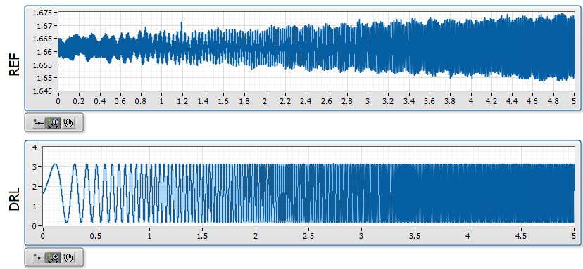
I use a NOR-9205 on a NOR-cDAQ-9184 and noticing some interesting dependencies of waveform on my sampling rate selected. It seems that small changes in the sample clock frequency have a significant impact on the measured waveform.
Quick background, I am in a position a signal with a ripple of mV ~ 10 with V 1.6 bias. I'm not interested in DC, only the AC signal but the NOR-9205 has only DC coupling. The application is a circuit where I expect simulations noise past the circuit must be greater than the higher noise frequencies. In the waveforms attached the background plot is the applied signal, and the top graph is the signal arising after that the signal was mostly annihilated. The two waveforms are measured with the NOR-9205.
I am aware that this measure is less than the precision of the NOR-9205, which has a maximum precision of ~ 3 mV in his +/-5V range. However, if I can't at least on the basis of shape which is good enough for me. I'm also now pretty curious that data acquisition is actually to create this

My best idea, is that it is a product of internal multiplexing of the 9205 with the DAC.
The first plot shows the waveform at 20 000 Hz, which is what I expected:
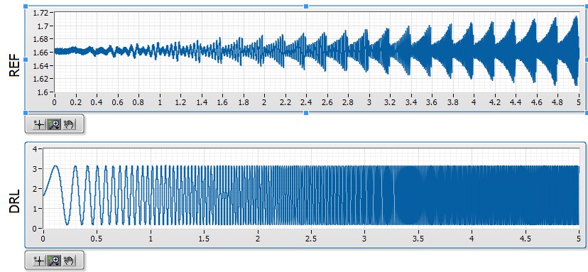
The second shows the waveform at 20 001 Hz, which seems to be modulated with a backup sawtooth:
The waveform looks as expected for 20 000, 20003, 20004, 20005, 20008, 20009, 20010 and Hz 20011. The waveform looks like modulated to 20001, 20002, 20006 and Hz 20007.
Ideally, I would like to understand this problem so that I can configure the measure in a stable way that I can count on the basic shape of the wave. Has anyone seen something similar?
-
2 channels of AI on a data acquisition with the range of different sensitivity
This vi is based on the 'new project' state machine on the home screen at the start of LV.
A time loop is parallel to the main loop of the state machine, shown in the picture.
It works continuously until you press the Exit button.
The problem seems to be in start this... > read >... stop start > read >... stop along the error line.
The reason for this clumsy arrangement power is measured voltages are in two lines of different sensitivity.
The shunt voltage is small and needs-. 2 to the range of V.2. The load voltage is greater and 09:50 V range is good.
In the initializing state, two separate vi 'create a channel' have been used to specify the range of voltage to the physical channel. The corresponding tasks are sent via via local variables.
DAQmx errors happen randomly, sometimes the first iteration, sometimes the 50th.
I tried to disable one or the other start > read > stop for the shunt voltage or load.
I tried replacing them with the DAQ assistant.
I tried various DAQmx vi: "wait" and "accomplishment of the tasks by resource cancel selected".
But error-50103 "specify resource is reserved" keeps popping up.
Is it possible to create two tasks on the device even when they are not used at the same time?
The only reason is to measure in two voltage ranges.
Win 7 Pro 64-bit
2014 LV database
Data acquisition equipment: USB-6210
Thank you.
This has been discussed many times. Do NOT use separate tasks. You can use different ranges for different channels with a single task. Just wire the task from one channel to another channel to create task.
You also use local variables when they are certainly not needed.
-
Real-time display at the high frequency of data acquisition with continuous recording
Hi all
I encountered a problem and you need help.
I collect tensions and corresponding currents via a card PCI-6221. While acquiriing data, I would like to see the values on a XY graph, so that I can also check current vs only voltage/current / time. In addition, data should be recorded on the acquisition.
First, I create hannels to analog input with the Virutal DAQmx channel create, then I set the sampling frequency and the mode and begin the tasks. The DAQmx.Read is placed in a while loop. Because of the high noise to signal, I want to average for example every 200 points of the current and acquired for this draw versus the average acquisition time or average voltage. The recording of the data should also appear in the while loop.
The first thing, I thought, was to run in continuous Mode data acquisition and utilization for example 10 k s/s sampling frequency. The DAQmx.Read is set to 1 D Wfm N Chan N Samp (there are 4 channels in total) and the number of samples per channel for example is 1000 to avoid the errors/subscribe for more of the buffer. Each of these packages of 1000 samples should be separatet (I use Index Array at the moment). After gaining separate waveforms out of table 1 d of waveforms, I extracted the value of Y to get items of waveform. The error that results must then be treated to get average values.
But how to get these averages without delaying my code?
My idea/concern is this: I've read 1000 samples after about 0.1 s. These then are divded into single waveforms, time information are subtracted, a sort of loop to sprawl is used (I don't know how this exactly), the data are transferred to a XY Chart and saved to a .dat file. After all that's happened (I hope I understood correctly the flow of data within a while loop), the code in the while loop again then 1000 samples read and are processed.
But if the treatment was too long the DAQmx.Read runs too late and cycle to cycle, reading buffer behind the generation of data on the card PCI-6221.
This concern is reasonable? And how can I get around this? Does anyone know a way to average and save the data?
I mean, the first thing that I would consider increasing the number of samples per channel, but this also increases the duration of the data processing.
The other question is on the calendar. If I understand correctly, the timestamp is generated once when the task starts (with the DAQmxStartTask) and the time difference betweeen the datapoints is then computed by 1 divded by the sampling frequency. However, if the treatment takes considerable time, how can I make sure, that this error does not accumulate?
I'm sorry for the long plain text!
You can find my attached example-vi(only to show roughly what I was thinking, I know there are two averaging-functions and the rate are not correctly set now).
Best wishes and thank you in advance,
MR. KSE
PS: I should add: imagine the acquisition of data running on a really old and slow PC, for example a Pentium III.
PPS: I do not know why, but I can't reach my vi...
-
Simultaneous to the AO and HAVE with the acquisition of data NOR USB 6001/MATLAB Toolbox
I am very new to data acquisition and bought a NI USB 6001 to start to learn. Because I can get free MATLAB through my University, I use Matlab data acquisition Toolkit as the data acquisition software.
My problem is that I get the following error message when I try to generate an AO (an LED voltage) signal and measure a signal I (voltage of a battery of 9V) simultaneously.
ATTENTION: This change is caused in the dump output data queue. Use queueOutputData for the queue data before the start of the object.
Hardware does not support the specified connection. Check the user manual of the device for the valid device routes and pinout.However to measure IA or by generating the AO each by themselves works perfectly well.
My Matlab script looks like this:
daq.getDevices;
s = DAQ.createSession ('or');
s.Rate = 1000;
s.DurationInSeconds = 10;
addAnalogInputChannel (s, 'Dev1', 'ai0', 'Voltage');
addAnalogOutputChannel (s, 'Dev1', 'ao0', 'Voltage');
aoVoltage = 1.8 + 0.1 * sin (linspace (0, 2 * pi, 10000))';
queueOutputData (s, aoVoltage);
s
startBackground (s);
Note that adding the channels HAVE and AO at the session also works, however I get the error mentioned at the start of the session. This is a limitation of my data acquisition hardware (I don't see something like that mentioned in the manual) or do I have to modify the script?
The pins connected for the LED are AO0 (+) and AO GND (-).
The pins connected to the battery are AI0 (+) and (-) AI4. (The problem is still there if I use the reference to the ground for AI)
6001 cannot make simultaneous tasks. Very standard limitation of the low-end hardware... just don't have on board computing resources to handle such things. Even the 621 x boards have only limited multitasking abilities.
Can intensify to a high range data acquisition ($$$) or buy a 2nd a low end and synchronize tasks in software (not as precise calendar). I've done two approaches, one is "best" really depends on demand... If low-cost or high-performance is a priority.
Maybe you are looking for
-
No sound on HDMI, image works fine but in the sound Manager tells me not connected HDMI
Hello I have a 1050ez tm2 and having problems with my HDMI port. When I connect the screen gets automatically duplicated and everything works fine, but when I try to play a movie with vlc for example I get not all sound through the TV, only on the ta
-
How can I recover ATI utility that I deleted by accident
I have windows xp
-
Entered in the wrong the static IP address and now can't come back. suggestions?
Running Windows7 and try to set an IP address for printer HP 6700 wireless. It has been 192.168.2.108; I changed it to 192.186.2.250 (implementing the 8 & 6). So, I restarted the router. The HP update IP address utility found the new address, I "r
-
Webcam for laptop HP 2000-210US
Hi there, I have Windows 7 installed on HP 2000-210US laptop. The other day I was with my webcam and the next day it stopped working. I checked the drivers, and now he is missing in Device Manager. I tried to download youcam (the one right they for m
-
WRT54g odd Page of DMZ: hacked? Corrupt?
I wonder why there are boxes and 30 00 inside the DMZ page. No other screenshots of the page of the DMZ for the WRT54g, I found on google images has them. Any ideas? : http://www.PostImage.org/image.php?v=aV1YkZd0