PIN DAQmx
Hi, I just bought the DAQmx, USB-6229. He was 2 meters and waveform out.
I don't know how to use these functions-counters and out waveform - using PFI 0-15, the lines of the PFI 0-15 is IN or OUT. What axes belong to the waveform on. No matter what this line can be used as INSIDE or OUTSIDE for meters and waveform PFI 16. Please advice.
Best regards;
JH
Tags: NI Software
Similar Questions
-
How can I configure DAQmx to count on the pin of PFI0 positives
I'm trying to track on a NI PCI-MIO-16XE-10 analog input lines, while in the same number of times the number of positives from triggering as I get to the pin of PFI0 I use LabView 2011 any help would be appreciated.
For your device, counter entries are by default as:
PFI 8 for Counter0
PFI 3 for Counter1
Just send it to PFI0 instead, see attachment.
-
Signal saturated in a task daqmx without wiring
Hello
I installed driver-daqmx on an SMU-8108 controller in order to acquire analog signals of several load cells. The task that I created used to work until I started to use an FPGA card to perform other tasks in the program.
Now, when I start my program, the output of the load cell is always 10.45... Volts, which means that more of the 10V output possible. There is no drifting but just a signal "saturated". Because I haven't found a bad wire, Earth or something similar, I have no other idea what could cause this signal problem.
Thanks for your suggestions.
Hi Henrik
I use a block of connection of the SCB-68 (R series). The amplifier output signal (see attachment) is connected to the AI + and HAVE pine trees (68 # and #34).
I added a resistance 100kOhm between HAVE + and I-ground and ground - HAVE and HAVE. It seems to work. Interestingly even resistance 100kOhm between HAVE + and HAVE ground seems to be enough...
Welcome and thank you very much
-
I am still fairly new to LabView, only it uses about 5 months, so bear with me.
I'm trying to understand why the DAQmx playback function runs slower I expect. I use a PCIe-6363 map connected to two BNC-2110 connector blocks. I run the attached code (Position AOM control_prod_cons) and producer while the loop takes about 14 ms to execute. Here's why this is a question:
The Subvi belongs to a larger structure that we use in our research lab to run our system of construction craft nanofabrication. You are using a computer-controlled turntable (wise move task), monitors of reading of the scene (spot monitor sensor) sensor and control a shutter that controls power to the sample (Subvi with lightning) laser. Up to 4 outputs analog and three analog inputs. The scene is being ordered to move in 5 steps of nanometer to a speed of 50 micrometers per second, a rate of analog output of 10,000 samples per second per channel (3 of them). The shutter has a rate much more low yield, at most 5 samples per second. Our goal is to synchronize the movement of the scene with the shutter, and so we must read the exact position of the scene using the analog inputs, one for each axis, x, y and z, vote as often as possible, even if in reality it didn't need to be more than one read each ms.
AOM control_prod_cons position takes two points in space that we wish to move between two points where the shutter must open/close. The first image in the flat sequence did some vector calculations to get the line that we write out the origin of the octant where x, y and z be positive by adding or subtracting, then making reflections around axes, if necessary. The end of x, y and z values (which are now all positive) are summed and placed later in the sequence. Coordinated sensor monitor are then read in (loop producer) and turn the same way coordinates the target have been transformed (consumer loop), then compared with the values of (x + y + z) end and start (0) and adjusted accordingly shutter. (For troubleshooting purposes, "off" is 2.5 and read the text file we entered to extract structure).
All the tests I've done so now tell me that the loop of the producer is the rate limiting step. For a line that is 30 microns long, with the displacement of scene I described above, I was 45 or 46 readings, that works on a read (on the three channels) once all the ~ 14 ms, or only 72 samples per second per channel, which is * very * slow for the card and is not acceptable for our application. Am I missing something? Why the producer loop takes 14 ms per iteration? I tried to reduce the sampling frequency of writing to 1000 samples per second per channel, but that did not alter the reading rate, so I'm not sure I can cela pins on the map.
I ran the DAQmx read function as a NChannel 1sample, read in a while loop like I do in more complicated VI, reading of the three analog inputs in a very simple VI who only reads the sensor monitors and nothing else and the reading rate was 2750 samples per channel (read 5000 samples through three channels in 1800 ms) , so I know that the card can read that fast.
I've also attached the highest lying VI that sets up the physical channels for adding information. I am also attaching a VI where the producer/consumer framework is not used. Also, this while loop took ~ 14 ms to exploit.
Sorry, that was so verbose, just try to do what I'm trying to erase. If you have any other questions, please just ask. Thanks in advance for your help.
Well I'll be darn. The "task AO is?" query seems to be the culprit. I have no memory of being always aware that there was such an expensive application. I don't know if I tried to make such a request in a tight loop before, but I'm a little surprised by the fact that I'm surprised. I don't know if anything is changed, but in case it's a secondary-ish effect, I use the new DAQmx 16.0
Another approach would be to use a property DAQmx writing node to query the Total number of the samples. It seems quite a bit faster.
-Kevin P
-
How to set DAQmx period task input terminal
I have a measurement period counter as task created in VB6.0 using Measurement Studio 8.6 and NOR-DAQmx. Is it possible to configure the input (door) to be PFI0 instead of the default Terminal.
Thanks, vecsol...
The terminals of the meter are wired on certain pins on the DAQ card. The door of the Terminal is not set for a 'default', the door of the meter is connected to a certain line of PFI - this cannot be changed. See help NI - DAQmx Device terminals for more information on PFI line corresponds to what terminal of the meter.
-
PXI-6133 Pulse frequency output and input with DAQmx
I am trying to set a pulse meter output frequency task and read this signal with a frequency counter input task input pulses. I use a 2 PXI-6133, each connected to a BNC-2090 case has. I want to output a square of a certain frequency with the task frequency meter pulse output and then read the frequency of this signal using a task of cost input frequency. I don't know how to property set up these tasks, or how to define which device to use for each heap. I don't know what terminals on the BNC-2090 is the counter of entry/sortient channels correspond to them because that is not displayed in the documentation of the PXI-6133 or documentation of BNC-2090.
Please see the attached VI for my attempt to put this in place. Currently, I get two errors:
(1) error-200452 took place at the property Node DAQmx channel meter Test - referred to as property is not supported by the device or is not applicable to the task.
2. the error-89136 at DAQmx Start Task - specified route cannot be met because the hardware does not support.
If I remove two channels of property DAQmx where I try to put the terminals for the counters, while the program is running, but then I know not what terminals on the BNC-2090 meters are connected to! This causes the DAQmx read for the cost in the tasks of frequency to timeout because it does not detect a signal.
I would really appreciate the help to properly configure these tasks and determine what terminals on the BNC-2090 case has the task of counter will work on.
I see a few problems in the code originally:
- For your CI task, you type is defined as a counter entry > frequency. But on the node property of DAQmx channel for this task, you modify the CI. Property of PulseWidth.Term. It should be CI. Freq.Term. set the entry regardless of the PFI line you do not want the input signal on. Tip: you don't have to type the name of the device in at all. Enter "PFI0", it's the same as "DevN/PFI0" since the unit has already been specified in the DAQmx Virtual Channel Create function. The name of the device, leaving aside will make your code more flexible where you decide later to change the name of the device.
- Maps of the S series, such as the 6133, do not have the same flexibility to change the output terminals of tasks of meter you might find with M or X series device. Page 83 of the S series manual watch what signals can be extracted to PFI lines - Ctr0Out is not one of these. Instead, Ctr0 out is, by default, pin 2. Cabling to a BNC-2090 6133 is certainly difficult to understand out (probably because the 2090 was designed to work with the materials of the E and M series), but if you compare the pinout of a PXI-6255 0 with the 6133 pinout connector, you will notice that they are essentially a match 1-1. Pin 2 is PFI12 on the 6255, so I assume the same for the 6133. All this to say, Ctr0Out always appears on the pin 2/PFI12 for the 6133 and you therefore cannot change the output terminal that your code is trying to do, having for result error-89136. Remove this node from the property altogether and the error should disappear.
-
Need help with counters on PCI-6221 (37-pin)
Hi all
I have a system with a PCIe 1429 connected to a Basler A504 camera and one I use a clock generator (SRS CG635) of 3.9 kHz for trig the image acquisition.
On the same system that I need to add a PCI 6221 37
PIN to acquire:-2 HAVE 39 kHz, synchronized with the acquisition of the image. (Sample of the 10 for each image)
-1 meter to measure a frequency
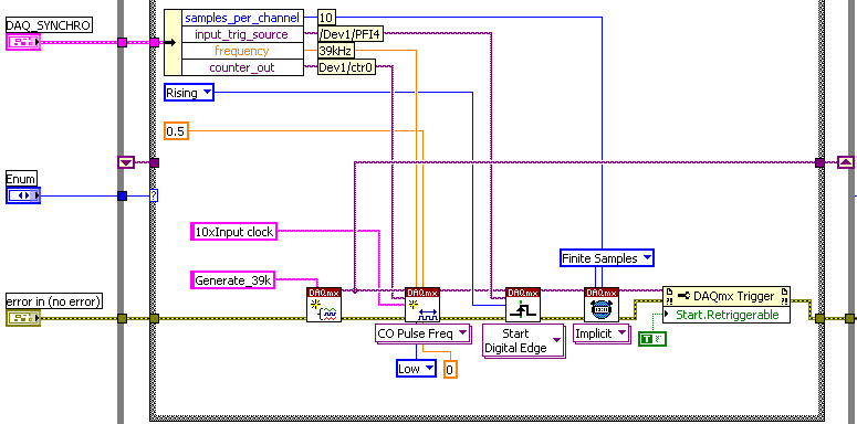
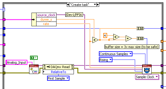
The accuracy of my clock of 3.9 kHz being much higher than what I have on the DAQ card, I thought that an interesting option would be to have a redeclenchables DAQmx task that generates impulses from 10 to 39 kHz for each pulse received from the clock and then use it to trigger the DAQmx AI task.
Of course this can only work if the 'trigger' sources that I defined for these two tasks do not take both counters that I have on the card.
So, let's describe the DAQmx tasks:
-Here is the one who generates the 39 kHz on 0, the counter of the 3.9 kHz I entered as a source on PFI 4 trig
-This is the task of analog input for which I put the trigger on 6 PFI.
It is: I have "softwarely" know the jury to deliver output (Ctr0) 6 FBP counter? And if so, how?
Thanks in advance for any help!
Maybe you missed something that I didn't really point out in my post. The method I described would use the external clock of 3.9 kHz precise as a sample clock, so you would * not * be in danger of loss of synchronization in 1 s per day. You need to only son of this clock signal in a stem of PFI available and configure the task to HAVE it as a result. The 80 + kHz clock that controls conversions within each sample cycle * would * be generated by the jury of 6221, but he don't would not accumulate any out-of-sync error because he gets "retriggered" on each edge of the 3.9 kHz precise clock.
-Kevin P
-
Express pins DAQ wire does not appear
Hello. I recently using DAQ and LabVIEW...
I use 8.6 OR DAQmx and LabVIEW with NI USB-6212 8.5 as the acquisition...
Here's my problem,
I try generated voltage (DC) at my actuator that is Honeywell ML7420A series with spec:
-Input signal: 0-10 or 2-10 Vdc
-Power supply: 24 Vac
As a first step, I'm going to the DAQ assistant express in the block diagram window, then choose generate--> voltage--> Channel Using--> test window.
In this window, I try to run the sample voltage and the actuator answer immediately, I think that the problem would be nothing. So I click the OK button, here is my problem, the DAQ vi is not a stem of wire! The DAQ vi who must have a PIN for error, given out etc does not appear, I try again and it still the same as before, I even try to change the driver and nothing is happen.
Are you know why it happen?
Can you recommend me what am I should I use if I am not using DAQ assistant express?
Thank you for your comments...
Good afternoon!
I hope you do well. We'll find the solution to your problem in the knowledge base article: why don't I have any input or output terminals on my DAQ Assistant in LabVIEW?
Just go to tools > Options > VI server and make sure the "ActiveX" is checked.
I hope this helps!
Kim W.
-
Can you have multiple nested DAQmx writing VI?
Hello everyone. I'm pretty new to Labview and am trying to find the best way to manage several instructions 'if' using a table of clusters and outputing to the various pins on a data acquisition module. Going to work to have a dozen DAQmx live write in the nested case statements, or will it cause errors?
The goal is to take the entries by the out of control and front panel based on schedules and user input values. Any suggestion would be appreciated.
I thank very you much in advance!
James
Of course, you can have several writing VI DAQmx.
Here is a tip that will save programming time you:
The Index Array feature is re-sizable! You don't need to break a wire table and 4 tables to Index and thread of the constants for each of them to get the individual items. Just drop a, and then drag the bottom of the knot to the bottom until you get 4 outputs. By default, they start at 0 and increment by 1 when you get off. You will get the elements 0, 1, 2, and 3 without having to associate the constants to the index entry.
I also recommend that, instead to use local variables, you keep the table of boolean in a thread that runs through all cases in a shift register. Just replace the item array for any element of the array you are editing in a particular case.
I have also modeled the code, you have no need for dozens of instructions box nested. For example, you have one ON and OFF cases in one of the nests. I'm assuming that the only difference is that you are wiring is real or fake. Wiring just the Boolean value. Various other code is duplicated between each case. The same for the upper levels of the nest. If you write to the acquisition of data in all cases, who move outside the structure of the case and just control what Boolean values to change the Interior structures of the case.
-
DAQmx create virtual channel (VI) error-229771 reports
Hello
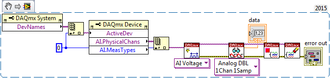
When in a project that I am working to get error-229771 code whenever I try to run 'DAQmx create Virtual Channel (VI)' this does not happen when I create a vi not in a project. The problem is that this project is very large and it if poster impossible to recreate. It's several hundred vi. Y at - it something that I missed in the forums and support that could explain this. I created the VI below in the project and outside the project. In the project, the error occurs outside the project, it runs without any problems.
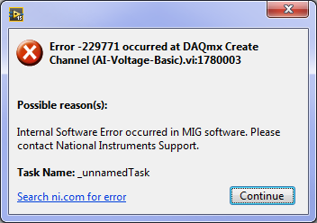
Message:
229771 error occurred at .vi:1780003 DAQmx create channel (I-voltage-Basic)
Possible reasons:
Internal software error has occurred in the MIG software. Please contact the support of National Instruments.
Task name: _unnamedTask
Any help would be appreciated. Thank you, Matt.
LabVIEW version: 15.052(32bit)
OR Max Version: 15.0.f0
NEITHER DAQmx Verson: 15
OS: windows 7 service pack 1
PC: Intel Core i7-2600, 8 GB of ram
Data Aquistion: NEITHER DAQ USB-6289 calibrated June 2015
This code snippet returns the name of the first channel of analog input on the device first, and then tries to create a task for her. The bed of the canal, then close the task.
Error message
Hi Matthew,
Thank you for following up after you fix your problem. I'm glad to hear that you do not encounter this problem more.
Here is an article that lists the reasons for this error (although unfortunately, I cannot pin down which is the exact cause in this case).
http://digital.NI.com/public.nsf/allkb/03123D0E8A36C48E862577A4005B6BAA
NOTE: This article specifies that the error occurs at startup task VI DAQmx. You do not use the start task VI, so the task starts automatically in the DAQmx Read function. The error will occur instead in the DAQmx virtual channel create, that you encounter in your error.
I hope this gives you an idea about what could have gone wrong, and I'm sorry he is no more details.
Good programming!
-
How to connect to the list of the pins for a redeclenchables pulse train
Hello
I'm relatively new toDAQmx, especially for the counters. I have problems to determine what pins to plug on the DAQ card. I would like to run the vi described here, but am not sure how to connect the card. I looked at the manual of the X series for the pinout descriptions, but I don't know how they apply to the program on this page. When I connect DOOR a meter, THE, A, B pins, etc.?
Any input on what to connect or pages that may make how to connect the counters would be very useful.
Thank you.
Your most recent post of links to an example more advanced sounding & I recommend that stick you with something simple to start.
Your first post links to such an an example where the signal of pulse train going out of Ctr0_Out. Ctr1 is used to make the trigger and the 'break' (enable / disable) Ctr0. However, much of this stuff is configured using some features of DAQmx such that you don't need to physically connect the pins between the two counters.
Only physical wiring that you need is to plug your physical digital trigger to the PFI1 signal and connect Ctr0_Out to some external thing must receive them. As long as your device is called "Dev1", I think this example to work.
I know there are some docs useful for more general info on the pins meter & behavior, but I don't remember quite so that I have not watched for them for many years. Meanwhile, here is a * little * bit General description I wrote myself once.
-Kevin P
-
NOR-DAQmx C to run two cards USB M series
Hello
I am a newbie in working with DAQmx system and need help on the synchronization of multiple USB DAQ devices. The goal is to start the collection on two USB DAQ for M-series card, and we use C codes (via the DAQmx ANSI C library) to do this. I read and resources OR more guides: "Several hardware DAQ synchronization" (http://www.ni.com/dataacquisition/videos.htm), and examples of code on the dev box NOR: "NOR-DAQmx: HAVE / simultaneous in CVI AO" (http://zone.ni.com/devzone/cda/epd/p/id/879).
My understanding is as follows:
1. set the first card as the master and export the signal 'StartTrigger' and 'SampleClock' PFI1 and PFI2 (the physical axis).
2. connect physically with pin PFI1 and PFI2 (sources) of MasterCard wire on pin of PFI0 and PFI1 (destination) in the slave card.
3. set the task of the slave to use the beginning of digital dashboard using PFI0 and configure the sample clock of the slave task to use the clock of the source of the exported signal from main task to PFI1 (the slave PIN).
So far the result does not work. The error still shows as if the physical connection is not recognized (I have not yet found a way to check if the signal exported successfully or not).
I have attached the instant routing table to the map created in the MAX and the code snippet I used.
Any help is welcome. Thank you!
Hi kusg.
DAQmx unclear that some PFI terminals on your two devices are interconnected, and you can't tell him that they are connected because DAQmx only supports connections inter-appareils for chassis PXI, not PFI terminals and cables of the RTSI. So export terminals PFI of Dev2 Dev1 task signals won't work.
However, you can export terminals PFI of Dev1 Dev1 task signals. Try to do this instead, and the error should go away (as I think it is to assume that it is error-89124).
In addition, when you use PFI, I recommend committing the master task before you begin the task of the slave, to start the master task does not generate unwanted edges digital:
DAQmxTaskControl (masterTask, DAQmx_Val_Commit);
DAQmxStartTask (slaveTask);
DAQmxStartTask (masterTask);
Brad
-
DAQmx and SCXI-1160 with 'DAQmx switch Open Relays.vi '.
Hello
I use DAQmx to pass the baton on a map of SPDT 16 SCXI-1160. When I run the 'DAQmx switch Open Relays.vi' with the entry "ch0/SC1Mod1 / ' I think the relay normally open position 'NO '. But this is not the case, the relay is in the position of the NC. Here are the steps I do a simple VI.
1. define the topology of the 'SC1Mod1' to '16/1160-inverter.
2. call the 'DAQmx switch Open Relays.vi' with the string "/ SC1Mod1/ch0.
3. then I take a physical measurement, with a multimeter on the SCXI-1324 terminal block and the relay is in position "NC".
4. If I run the "DAQmx get relay switch Position" he's back "Open"!
Is this the good behavior, and if so can someone explain the logic behind it.
Thanks in advance,
Michel
Hey Michael,
Sorry, I didn't know that you were actually able to control the relay and you receive just the reverse logic. To answer your question, on the SCXI-1160 module, there are three connections for each channel: COM, NO pine and pine of NC code. Reset, COM is connected to the spindle of the NC. When you issue a command to OPEN channel 0, COM will stay connected to the NC pin, even if the software indicates now that the PIN is open. When you issue a command NARROW-gauge 0, COM will be now connected to pin number and not on the spindle of the NC.
A better way to think of it, is to focus only on the relationship between COM and no. pine. When you send a BLANKET order, this connection between COM and no. will be open. When you send a CLOSE command, the connection between COM and no. will be closed. Consult this manual for a visualization of how this switch is set up: http://www.ni.com/pdf/manuals/320513b.pdf. Refer to page 2-9 and 2-14 of this manual for pinout.
-Nathan H
-
DAQmx: With relaxing break pulse blocking
I have a NI 9401 module in a chassis 9171 and stand at the door of the output of a counter with the release of another counter. 1 meter (the signal to be blocked) generates a 3 Mhz signal and meter from 0 (the door) generates a 10 Hz signal that is sent outside to door pin of 1 meter. I expect this would be counter 1 door signal to produce the 3 Mhz flashes only when the counter 0 is high, but the wiring had no effect on the output of the 1 meter, it has always generated a continuous pulse train of 3 Mhz. I found that a code is necessary to get a counter to pay attention to the signal to his door pin (this message was particularly useful) and it can be done with the node property relaxing break. After you have configured the node, however, I fell into this error:
Error-20124 occurred at DAQmx start Task.vi:2
Lines 4 to 7 of this port are configured for the entry. Cannot configure these lines for output at this time.I'm quite puzzled by the present. The problem seems to come try it designate 5 PFI ('CTR 1 door' on the 9401) as the source of relaxing break. If anything, I think the error would be that lines 4-7 are configured for output, since these lines are grouped under CTR 1, which is configured as a channel of CO to generate the 3 Mhz pulse train, and the definition of line 5 as the break source changes the configuration on an entry. Looking for this error in the forums OR and Google isn't pulling up of troubleshooting information. I tried to create a task to configure line 5 as a separate digital input channel, but then I get the error saying (error-200125) opposite that lines 4-7 are configured for output and cannot be configured at the entrance, to make things more confusing.
Any thoughts would be appreciated. I'm afraid I'm missing something obvious about blocking the impulses or CO channel configuration as I continue to read that one of the benefits of DAQmx on Legacy DAQ, is that it makes easier routing signal. I'm using LabVIEW 2012 (32 bit) with DAQmx 9.5.5 installed.
Hi agoncalves,
I took a glance at your VI and I see two immediate problems:
1. it is not guaranteed that the two tasks will be reserve before the start of each one. This explains your error and why it seems confusing. The 9401 is configurable nibble, but you cannot change the direction while the device is being used (why the reserves are important). The module starts with two nibbles the input value. Your first task causes an exit so it switches direction on one of them. When your task is committed (started), it hangs in this configuration. The second task then also try an output drive, but on the other nibble that is entered and can not be activated because the first task is currently running. The solution is to use the thread of the error to force the order of execution (or use a flat sequence structure).
2. you won't run out of problems with your trigger signal unless that connected you to a separate entrance (and put the two trains of pulses on the nibble even). You can change that by setting the property of canal CO. Pulse.Term. that's if you want to spend your signal through a few circuits external and back in. If you use the signal directly, you can just use it internally. By example/cDAQ1Mod1/ctr0InternalOutput
-
Traditional DAQ against DAQmx Counter
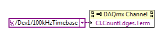
I'm trying to convert an existing legacy application written in LabVIEW LabVIEW 2012 6. I have a problem with a traditional Daq counter. Specicically the VI "event or time meter Config.vi. In the attached VI, you can see that 1 meter is configured to count the cycles of an internal signal, not a PIN counter SOURCE signal. This configuration generates an integer for each cycle of the internal signal: every 10 microseconds in this case. I can't find a way to replicate this feature in DAQmx. I use a DAQCard-6062E (PCMCIA Slot) card in a Dell D620 Laptop. I tried to attach a fully functional VI, but get the error 'the content of the attachment does not match the type of file.' to fix this I had to fix a JPG image. I've included comments in VI to clarify things. Any help appreciated. Thank you.
In DAQmx you can achieve the same result by setting the terminal entrance for a task of edge to the time base County internal 100 kHz:
The 100 kHz Timebase is considered to be a "Advanced terminal" (don't get started me on the topic) so see in the dropdown menu, you must right-click on the control / constant and select the appropriate name of I/O filtering option.
Best regards
Maybe you are looking for
-
My old themes do not work with this version of FF.
On the latest upgrades FF bit the themes available considerably decreased and now the majority of my registered themes said "not compatible with this version of FF. Whyzat?
-
After update to a version after FlashPlayer 11.02 when you open a window with flash videos on, next to the Firefox process in the taskbar appears a new process with the Flash Player icon and the video window is placed in the upper left corner and can
-
BSOD in Windows 7 since the addition of Office 07 and updates Windows.
How can I keep my computer from HP 1 month (Windows 7 Home Premium 64-bit) to close down and blue-screening at random times? First thing I did when I got it was to slowly add programs I used on XP safely in the past. I run Comcast w/McAfee and viru
-
Can I put my HP pavilions, n CPU GPU
Hey guys,. wanted to know if I could spend my HP Pavilion n218ax the specs for the laptop are: CPU: AMD A4-5000 GPU: Radeon AMD 8670M And I wanted to know if I can play games such as Skyrim, Need For Speed, Farcry 3 or Battlefield 3 Thank you!
-
U330 DVD recordable media types
What types of media are accepted for the double disc layer recordable DVD in my new Ideapad U330? JJP