Playback of digital input [FPGA] - NI 9401 - questions?
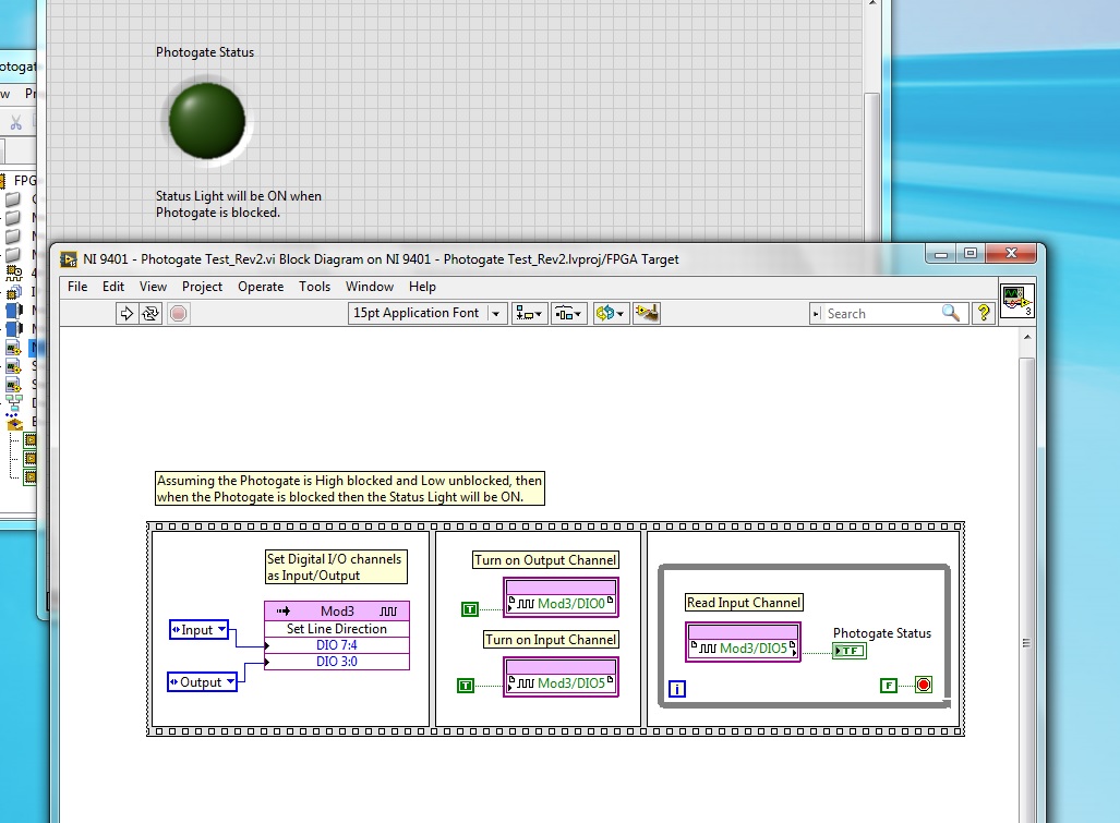
I'm having some trouble with the digital input NI 9401, which is to have a uniform reading. I have a photogate that power of a digital output is turned off and goes in to a digital input module, but I can't read the entry several times. My LED flashes once and never again will blink until I restart my CRIO or recompile. I have launched the ports of entry and exit, their market and constantly for loop. Any idea what's going on?
Hi Allan,
Why you "light up" a channel of entry?
Writing a value to a DIO PIN is usually for outings!
What is connected to your PIN DIO 5? Have you checked the entry with a DMM measure?
How long the impulses are measured with this entry? Do you really you can see short pulses of light flashing?
Tags: NI Software
Similar Questions
-
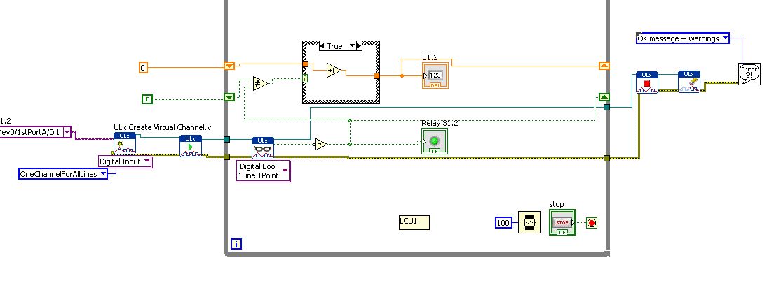
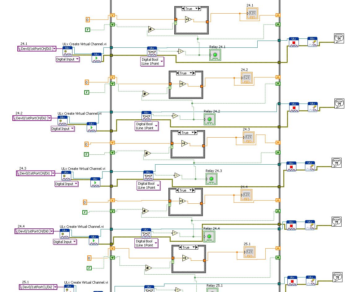
How to combine several digital inputs for playback?
Hi comrade Labview users.
I just started using LabView and I am very new to it. I know him understand how it works and you have something to work, but I need to be more effective.
I use DIO96H - USB DAQ Measurement Computing, which includes 96 digital inputs. I use the DAQ to acquire the activations of relay and record the number of times the relays flips.
Basically, I created a digital input read and then copy & pasted 95 times... it works but I know that's not the best way to use LabView.
How can I change the digital input (Di1/1stPortA/dev0) in multiples so that it iterates through all 96 channels without copying and pasting the same pattern over and over again?
Leon
You have the correct polymorphic instance for playback? Once again, for the material OR it would be a NChan Read. There should be a similar choice if I remember correctly.
-
Question of the digital input USB-6009
Hello
I use USB-6009. I have problem in Input.I digital did not connect anything on all channels. But all of the DI/O channels generate 5 volts. And I tested the DI/operating system in the Test Panel also. All digital inputs are high. How I use it? Please suggest me the solution.
You're the one who said it was generating 5V. And I said that a fine should be detected as a logic one. Connect a gnd input.
When it starts, all of the default value of I/O at the entrances.
-
NI 9421 - Digital input Module
Hello
We have a 9073 cRIO chassis and a digital input module (NI 9421). We installed also driver on this website - http://sine.ni.com/psp/app/doc/p/id/psp-177/lang/en and added 'modules C series' under the 'chassis (cRIO - 9073)"as shown in the illustration #1 as an attachment.
True to use 9421 is this way? And should we right click and select "deploy all '? And how can we resolve the conflict as pictured #2?
Thank you...
Hey drycsr,
First of all, make sure you have the drivers and rt versions listed here:
FTP://FTP.NI.com/pub/DevZone/tut/crio_software_versions.htm
Since you seem to have most of the currently running system, I think that you do not have those are installed.
To solve the problem in photo 2, follow the instructions to install on your cRIO scan engine support. This document is for PXI chassis, but it explains the general process:
http://digital.NI.com/public.nsf/allkb/D170D1AF82303EA086256B4200780579?OpenDocument
This document may also be useful:
http://zone.NI.com/DevZone/CDA/tut/p/ID/7191
As for your other question, you seem to be using the hybrid mode, which uses both FPGA (you have your module to your FPGA project level) and the scan mode of the interface (you have your module to the "frame" of your project level). This is not necessarily recommended for reasons explained here: http://ae.natinst.com/public.nsf/web/searchinternal/61276465e3043c0c8625749e005cc8a1
Scan by itself is discussed here: http://zone.ni.com/devzone/cda/tut/p/id/7338
FPGA and scan mode to discuss in the guides started can be found here:
http://sine.NI.com/NP/app/main/p/AP/global/lang/en/PG/1/SN/N24:cRIO/fmid/104
Good luck.
-
Hello
I searched for centuries for the answer to what I thought was a simple question - the iMac has one digital input (optical or other)?
I know that the headphone port doubles as an analog audio to as well as an optical digital output, but this port also accepts input optical? If not, is it possible to enter a digital signal via a USB port?
I have an iMac (20-inch, mid 2007).
Thanks to all who can help.
AL
Yes exit usb audio and are truly comprehensive external soundcards, they can have any type of entry and exit of the machine to be desired that they have
and if they do a driver of OS x for him it's just a matter of connection installing the driver and choosing the entry in system preferences for being that
If the audio minijack that also take in charge the headset for iPhone I believe support the digital input and I don't know if
-
Digital electronics FPGA Board Hardware Driver for Windows 10
My son just made me aware that his school has a dozen of National Instruments Digital Electronics FPGA boards, but they have never been able to get them to work or actually use them in the curriculum. It seems that he has left his instructor know that I worked with FPGA Xilinx for more than 10 years and now everyone counting on me to get these maps work. The issue seems to be the USB driver. According to the manual, I tried DEFB2012_5_2.exe which simply refused to run on this machine Win 10 x 64. DEFB_4_3.exe ran, but complained that LabView components have not been installed and that it would not continue. Could someone tell me please how to install USB driver ONLY so that we can download files of bits with IMPACT? In terms of a school budget, the investment they have in these maps is not negligible. Thank you.
Hello Dave and TGregor,
I hope I can clear some things here. I'm sorry that you run in so many questions with your boards OF FPGA.
First of all, direct responses:
The LabVIEW FPGA 2015 driver should install the components needed to use the Board with Xilinx tools on WINDOWS 7, it will not work on any system more recent that the pilot has been developed before the release of Windows 8 and 10.
http://www.NI.com/download/NI-Digital-Electronics-FPGA-Board-driver-software-2015/5857/en/
My recommendation for Windows 8 or 10 is rather install Xilinx ISE you find on Xilinx website or on the downloads page OR:
https://www.Xilinx.com/products/design-tools/ISE-design-suite.html
http://www.NI.com/download/LabVIEW-FPGA-Module-2016/6231/en/
The difficulty that you face here is that tool Xilinx ISE is officially supported only on Windows 7 and below. So even though I think it will work (and it will move to the difference in the link of the above driver OF FPGA) for Windows 8 and 10, you can continue to deal with certain issues.
Now you are all looking to program the FPGA using an HDL, Multisim and LabVIEW? If you just use an HDL, you should be all set to go and in the dev environment, you had planned using the program. Circuit design of Multisim 'S simulation tool which includes a complete library of graphic digital components. A digital circuit can be built using the graphical logic gates in Multisim then downloaded directly on the FPGA without first having to learn VHDL or Verilog. It is quite popular among the logical classes digital introduction and we can help you by establishes that as well if you are interested.
For anyone else who might stumble upon this page, I want to make sure you are all aware that, while the Board of Directors OF FPGA is still supported and sold, it has been developed a number of years and has recently been replaced by the Council for development of the digital system (DSDB)that uses a 7020 architecting and has much periphrials more to the program than the FPGA OF. So I know that it is not useful for the current issue, but anyone looking for if they would like to buy more OF FPGA boards, I recommend watching the DSDB instead.
Thank you!
-
Hello
I am relative new to LabWindows.
I have a program that starts when I press a button. The program controls a motor. Now I press a button on the motor and the program must cease (Safty Stop). The button is connected to a digital input on my card (PCI Express 6343). Now, I have the question, how do I program the interruption? I know not how do in CVI (controls the digital input whenever the program runs).
I hope someone can help me.
Best regards
The starting point must be to look relevant examples that NEITHER provide:
ReadDigChan - ChangeDetection.prj
and
ReadDigChan - ChangeDetectionEvent.prj
However, I must advice against using a PC as a "Safety Stop". As a general rule, the PC are completely inappropriate to the core functions of security, unless you follow the standard IEC 62304 relevent to the letter. Tip: it's hard to do with a PC. To implement safety functions such as emergency and interlocks stops you buy much better a specialist dedicated safety relay and following the instructions of the manufacturer. If life-threatening energy (either electric or medcanical) may be present, then consult a professional engineer.
-
Hello
After reading everything that specifications and manuals, I decided to ask a general question.
In the data sheets, user guides I've read, in general, there are two warnings for DIO:
-Do not connect the outputs digital circuits which operates above the limits.
-Do not drive the line with tensions outside its operating range.
Generally speaking they tell me I need to know when dealing with output and voltage when dealing with entries. So I have this question, can I wire a power supply for digital inputs directly without exceeding its "beach of normal operation and without any protection circuit? In fact, my feelings, this is not possible. But why certain documents produced clearly mention that the impedance internal inputs while that of others is not clear those? How can I determine if I can connect a signal directly to an entry (for example USB-6525 indicates a current limiter circuit, but I don't see a clear explanation in the datasheet USB-6251)?
As long as the input voltages are within specified limits, no damage will be the DAQ hardware. Logic devices often have two lines of non overlapping input, one for low input and high input. If the input voltage lies between the beaches, the performance of the device can be unpredictable. Also, check your power supply to make sure that this doesn't not exceeding when turned on or off as that could exceed the DAQ limit.
Lynn
-
6259 switch digital input to output
Hi all
I use the NI PXI-6259. One of the digital inputs I want to switch to digital output, send a serial code and switch again one digital input.
Does anyone have experience with this kind of configuration change during execution of the VI program.
Thank you
Basically delete the task that he had as an input, create another task DAQmx with channel configured as output, this task, erase it, create the task with channel configured as an input.
If you need a tight with switching schedule, I wouldn't recommend this Board. You may need to set up a Council of RIO with LabVIEW FPGA.
-
Digital input line showing an entry without connected equipment
Hello
I have a feeling, this is a silly question, but here goes. I have the VI below to read the entry of an analogue of the ADC0803LCN to digital converter through 8 lines.
The DAQ assistant is configured to read a digital input for all 8 lines and outputs in a matrix of LED that outputs then a digital indicator to show the binary value.
However even if I don't have the connected equipment and run the program, all lights are lit and on my multimeter I read + 5V to each line. I'm puzzled why I get an output voltage in each line when 'acquire Digital Input' works and why LEDs are HIGH without input logical proof. Even when it is connected to the material, which runs correctly, it still shows all logical LED HIGH with the release of material would not justify this. Any help would be great, thanks. I'm a Newbie, just to be clear
 , thanks.
Material is - pressure sensor Honeywell Trustability--> ADC0803LCN--> NI USB 6501
Hi beginner,
the answer is shown on page 14 of the Manual of USB6501...
(It is named "PR"
 )
) -
One button dialogue by digital input
Hello
A question about the Vi of dialog a button. I have a request I want to change. We have a physical button connected to a digital input when it is pushed on Board that we want to move forward in the labview program. This is just a momentary pushbutton if. The way his game up to now the user is told to press the Start button and click OK in the dialog box only one button. See code. The way its programmed, they have to hold the button down and click OK. Works great so far.
We change the environment to give the operator the ability to use the keys by a strop when the unit under test, which means that they will no longer able to click with the mouse. This code is used in quite a few places... I was wondering if there was a real quick way to change this so that the user should not click on OK to continue in the Code.
See attachment!
Thank you
An indicator of the great string on the front panel. Display the prompt of the indicator. You can change the color or to Flash through property nodes, if you wish. Clear the flag by writing an empty string when you push the external button.
you need to hide the other parts of the façade while the prompt, you can use the Visible property for the KPI tabs. A tab with only the quick flag looks a lot like a dialog box or be customized in just like you want. Make tab an indicator (change control) and what page by simply writing to its controlling terminal. You can do some very versatile user interfaces with relatively little effort programming like this.
Lynn
-
Digital input to Toshiba 46TL-> no analog audio output to amplifier
Hi all
When I connect a video source (e.g. computer laptop via DLNA) to my 46TL, output TV audio analog (red/white taken connected to an amplifier) does not work.
It does, however, watching television.
Is it possible to configure the TV to read the audio data from digital input (HDMI/DLNA) to the analog output?
Thank you for the help
Not quite what series of TLxxx you have, but for example the TL938 supports a digital (optical) audio output port that provides a digital audio signal.
Why n t connect the amplifier to the TV using this Jack?Connectors for component video / audio to the rear of the TV are the ports of ENTRY and not the OUTPUT ports. So, you can send an audio signal to the TV and not the amplifier output.
-
How can I set up a digital input task to read continuous samples?
I am trying to create an exclusively digital task that will make digital readings at a rate timed by the material using a PCIe-6509. However, when I try to put the task timing as follows (which works on a PCIe-6509), I get the following error:
Requested value is not supported for this property value. The value of the property may be invalid because it is in conflict with another property.
Property: NationalInstruments.DAQmx.Timing.SampleTimingType
Required value: NationalInstruments.DAQmx.SampleTimingType.SampleClock
Possible values: NationalInstruments.DAQmx.SampleTimingType.OnDemand, NationalInstruments.DAQmx.SampleTimingType.ChangeDetection
Task name: DigitalInputTask
State code:-200077
The relevant parts of my code are:
public class DigitalInputReader: IDisposable
{
public DigitalInputReader()
{
dataReadyHandler = new System.AsyncCallback (DataReadyEventHandler);daqmxTask = new DigitalInputTask();
daqmxTask.Configure (Globals.NI);daqmxTask.Control (TaskAction.Verify);
daqmxTask.Control (TaskAction.Commit);daqmxReader = new DigitalMultiChannelReader (daqmxTask.Stream);
}public class DigitalInputTask: task
{public DigitalInputTask(): {base ("DigitalInputTask")}
public virtual void Configure (NiConfiguration niConfig)
{
<= niconfig.digitalinputs.count="" -="" 1;="">
{
String physicalChannelName = niConfig.Device + "/ port" + niConfig.DigitalInputs [i]. Port.ToString () + "/ line" + niConfig.DigitalInputs [i]. Channel.ToString ();
String nameToAssignToChannel = niConfig.DigitalInputs [i]. Name;DIChannel ch is this. DIChannels.CreateChannel (physicalChannelName, nameToAssignToChannel, ChannelLineGrouping.OneChannelForEachLine);
c. InvertLines = niConfig.DigitalInputs [i]. InvertLines;
}
var signalSource = "";
This. Timing.ConfigureSampleClock (signalSource, Globals.MachineSettings.SampleRate, SampleClockActiveEdge.Rising, SampleQuantityMode.ContinuousSamples);// Globals.MachineSettings.SamplesPerChannel);
}
}The last call to Task.Timing.ConfigureSampleClock, it's which throw errors.
Of the options available, or SampleTimingType.OnDemand or NationalInstruments.DAQmx.SampleTimingType.ChangeDetection provide the same precisely timed calls that I am familiar with the analog input interruptions.
How is it possible in a digital task? I mean, it seems that I could set up another task to do call by material for the production of a clock signal and use the ChangeDetection synchronization mode, but this seems a bit complicated for what should be easy to do. What Miss me?
Update: I thought about it. You cannot call ConfigureSampleClock when the digital input card is a device of 650 x, because these devices have any automated examples of clock. They are configured to run in mode default finite samples. You must make all sample synchronizing with these devices in the software.
Be cautious, however, because the .NET timers ensure they put any faster than their scheduled interval. In practice, they are usually 5 to 10 ms slow by tick. This means that if you want to read samples every 100 ms by sample clock, you'd end up reading all 108 ms samples. All counters based on the elapsed time and number of samples would be away after a few seconds of it.
Instead, you must do one of four things: write a doggone driver that runs in ring 0 and interfaces with the PCIe card in the required interval (i.e. on NC, not you, in practice), tolerate the inclination of the clock, use a multimedia timer as an interruption audio or video that is more likely to respond to the correct interval, or , my solution, an accurate clock allows you to set the interval of the timer. I wrote the following code to the timer:
var CorrectiveStopwatch = new System.Diagnostics.Stopwatch();

var CorrectedTimer = new System.Timers.Timer()

{
Interval = targetInterval,
AutoReset = true,
};
CorrectedTimer.Elapsed += (o, e) =>
{
var actualMilliseconds =;Adjust the next tick so that it's accurate
EG: Stopwatch says we're at 2015 ms, we should be at 2000 ms
2000 + 100 - 2015 = 85 and should trigger at the right time
var StopwatchCorrectedElapsedMilliseconds = newInterval +.
targetInterval-
CorrectiveStopwatch.ElapsedMilliseconds;If we're over 1 target interval too slow, trigger ASAP!
<=>
{
NvelIntervalle = 1;
}CorrectedTimer.Interval = NvelIntervalle;
StopwatchCorrectedElapsedMilliseconds += targetInterval;
};I hope this helps someone.
-
Reduce the period of sampling of the digital inputs of NOR-USB-6009
Hello
I need to read a line of digital input in the NI USB-6009 using NOR Express 2013 Signal box. I selected 1 sample (upon request) as acquisition mode. I need to define a smaller sampling period as 1 MS, but it gives error too short sampling period: "the current sampling period is too short. Please specify a longer sampling period. ».
I do not understand the reason for it and a way to slove this.Any help would be greatly appreciated!
Thank you!!
The 6009 doesn't have a clock that you can set for a sampling period. According to the specifications, the digital I/o is software programmed - sample on request you use now. I'm not at all familiar with SignalExpress but I don't think that you can find near a reliable khz sampling frequency on Windows or any other os non-deterministic.
-
Hello
Is it possible to trigger action digital input using the signal I want to measure? In the example:
I want to measure PWM on P0.0 after first rising edge PWM on P0.0, but using only this line P0.0 (no PFI in use, only one used digital entry).
IM using X SERIES USB-6353.
Some DAQ cards can trigger on analog edge of the signal you want to measure. If a DI data extraction, it is possible to select only the PFI or similar as trigger. What is your application? What you want to achieve?
I can imagine you could workaround: record streaming samples of DI and do a SW trigger in your program, so you can get the same samples prédéclenchés (as in a digital oscilloscope).
Maybe you are looking for
-
Impossible to use Time Machine on Airport Extreme
Back in June, I brought a laptop HD work to save the laptop. It's something I have done 3 times a year, in addition to using Time Machine on my 1 TB Airport Extreme. Well, when I did that, I went from 'H Time Capsule' to 'Brian's Portable HD. Everyth
-
Function to be used in last registration site directory disappeared?
In previous versions of Firefox it remind my save directories based on the site I was downloading, but that worked great, it seems that is is now. After some research the topic function: config called "browser.download.lastDir.savePerSite", but is no
-
Need to transfer/copy Firefox Bookmarks from HD Vista Win7 new system.
My Vista system motherboard is dead, so bought the new Windows 7 system and have old Vista drive works as second data drive. When you install Windows 7, installed Firefox 4.0 (had 3. XX on Vista). I want to copy my favorites to the new system.How can
-
Y the trash emptied extension I close down my unit?
The Recycle Bin is emptied whenever I quit my unit?
-
can not send or transmit attachments; email is fine.
Sometimes, I have a kind of 'hang up' where I can't front/send no matter what size email attachment at all. the email will work very well for a month and all of a sudden I can send emails, attachments, or sometimes for 2 days to 2 weeks. It seems t